EP2245307B1 - Compresseur à pompe hydraulique et procédé pour produire un tel compresseur - Google Patents
Compresseur à pompe hydraulique et procédé pour produire un tel compresseur Download PDFInfo
- Publication number
- EP2245307B1 EP2245307B1 EP09703144.7A EP09703144A EP2245307B1 EP 2245307 B1 EP2245307 B1 EP 2245307B1 EP 09703144 A EP09703144 A EP 09703144A EP 2245307 B1 EP2245307 B1 EP 2245307B1
- Authority
- EP
- European Patent Office
- Prior art keywords
- compressor
- hydraulic pump
- crankshaft
- extension
- housing
- Prior art date
- Legal status (The legal status is an assumption and is not a legal conclusion. Google has not performed a legal analysis and makes no representation as to the accuracy of the status listed.)
- Not-in-force
Links
- 238000004519 manufacturing process Methods 0.000 title claims description 6
- 238000001816 cooling Methods 0.000 claims description 3
- 238000000034 method Methods 0.000 claims description 3
- 239000002826 coolant Substances 0.000 description 3
- 244000027321 Lychnis chalcedonica Species 0.000 description 2
- 238000002485 combustion reaction Methods 0.000 description 2
- 230000008878 coupling Effects 0.000 description 2
- 238000010168 coupling process Methods 0.000 description 2
- 238000005859 coupling reaction Methods 0.000 description 2
- 230000004323 axial length Effects 0.000 description 1
- 230000001419 dependent effect Effects 0.000 description 1
- 239000000725 suspension Substances 0.000 description 1
Images
Classifications
-
- F—MECHANICAL ENGINEERING; LIGHTING; HEATING; WEAPONS; BLASTING
- F04—POSITIVE - DISPLACEMENT MACHINES FOR LIQUIDS; PUMPS FOR LIQUIDS OR ELASTIC FLUIDS
- F04B—POSITIVE-DISPLACEMENT MACHINES FOR LIQUIDS; PUMPS
- F04B39/00—Component parts, details, or accessories, of pumps or pumping systems specially adapted for elastic fluids, not otherwise provided for in, or of interest apart from, groups F04B25/00 - F04B37/00
- F04B39/0094—Component parts, details, or accessories, of pumps or pumping systems specially adapted for elastic fluids, not otherwise provided for in, or of interest apart from, groups F04B25/00 - F04B37/00 crankshaft
-
- F—MECHANICAL ENGINEERING; LIGHTING; HEATING; WEAPONS; BLASTING
- F04—POSITIVE - DISPLACEMENT MACHINES FOR LIQUIDS; PUMPS FOR LIQUIDS OR ELASTIC FLUIDS
- F04B—POSITIVE-DISPLACEMENT MACHINES FOR LIQUIDS; PUMPS
- F04B39/00—Component parts, details, or accessories, of pumps or pumping systems specially adapted for elastic fluids, not otherwise provided for in, or of interest apart from, groups F04B25/00 - F04B37/00
- F04B39/06—Cooling; Heating; Prevention of freezing
- F04B39/064—Cooling by a cooling jacket in the pump casing
-
- F—MECHANICAL ENGINEERING; LIGHTING; HEATING; WEAPONS; BLASTING
- F04—POSITIVE - DISPLACEMENT MACHINES FOR LIQUIDS; PUMPS FOR LIQUIDS OR ELASTIC FLUIDS
- F04B—POSITIVE-DISPLACEMENT MACHINES FOR LIQUIDS; PUMPS
- F04B39/00—Component parts, details, or accessories, of pumps or pumping systems specially adapted for elastic fluids, not otherwise provided for in, or of interest apart from, groups F04B25/00 - F04B37/00
- F04B39/14—Provisions for readily assembling or disassembling
-
- F—MECHANICAL ENGINEERING; LIGHTING; HEATING; WEAPONS; BLASTING
- F04—POSITIVE - DISPLACEMENT MACHINES FOR LIQUIDS; PUMPS FOR LIQUIDS OR ELASTIC FLUIDS
- F04B—POSITIVE-DISPLACEMENT MACHINES FOR LIQUIDS; PUMPS
- F04B41/00—Pumping installations or systems specially adapted for elastic fluids
- F04B41/06—Combinations of two or more pumps
-
- F—MECHANICAL ENGINEERING; LIGHTING; HEATING; WEAPONS; BLASTING
- F04—POSITIVE - DISPLACEMENT MACHINES FOR LIQUIDS; PUMPS FOR LIQUIDS OR ELASTIC FLUIDS
- F04B—POSITIVE-DISPLACEMENT MACHINES FOR LIQUIDS; PUMPS
- F04B23/00—Pumping installations or systems
- F04B23/04—Combinations of two or more pumps
- F04B23/08—Combinations of two or more pumps the pumps being of different types
- F04B23/10—Combinations of two or more pumps the pumps being of different types at least one pump being of the reciprocating positive-displacement type
- F04B23/103—Combinations of two or more pumps the pumps being of different types at least one pump being of the reciprocating positive-displacement type being a radial piston pump
Definitions
- the invention relates to a system comprising a compressor and a hydraulic pump for use in a commercial vehicle, wherein the compressor comprises a crankshaft for driving the compressor and wherein the hydraulic pump is driven by an extension of the crankshaft, wherein the crankshaft is supported by a ball bearing, and wherein the compressor and the hydraulic pump are integrated in a common housing.
- the invention further relates to a method for producing a system with a compressor and a hydraulic pump for use in a commercial vehicle, wherein the compressor comprises a crankshaft for driving the compressor, the hydraulic pump is driven by an extension of the crankshaft and the compressor and the hydraulic pump in a common housing are integrated, wherein the shaft is inserted from the side facing away from the hydraulic pump in the common housing.
- Modern commercial vehicles have many subsystems that are operated with compressed air. These include, for example, an air-operated service brake or air suspension.
- a compressed air supply device is normally provided in the utility vehicle, which comprises a compressor.
- This compressor is mechanically driven by the combustion engine of the commercial vehicle.
- the coupling of the compressor is usually carried out via a toothing at one end of the crankshaft of the internal combustion engine.
- the compressor itself has a crankshaft, on the side facing away from the toothing often a hydraulic pump, for example a power steering pump, is arranged.
- connection of the hydraulic pump to the shaft of the compressor takes place in the prior art with the help of a radial clearance bearing, for example a Maltese cross, or a multi-tooth bearing, which can handle a higher torque but tolerates a lesser clearance compared to the Maltese cross.
- the radial play compensation bearing is necessary because the shaft is guided into the compressor on the drive side with a simple slide bearing, whereby a fairly large clearance of up to 0.1 mm is permitted.
- the disadvantage here is in particular the complex connection structure between the compressor and hydraulic pump and the necessary seals between the two separate housings.
- a system is known with a compressor and a hydraulic pump, wherein the hydraulic pump is driven by an extension of the crankshaft of the compressor, and wherein the crankshaft is mounted with a ball bearing.
- a system is known with a compressor and a high pressure oil pump, wherein the high pressure oil pump is designed as a gear pump, and wherein the gear pump is coupled via balls as coupling members to the compressor.
- the US 5,497,742 A describes a system with a compressor and a pump, wherein a compressor driving shaft is supported by a ball bearing.
- the DE 10 2005 059 491 A1 describes a water-cooled piston compressor, wherein coolant-carrying coolant channels are provided in a double-walled region of the cylinder housing.
- the invention has for its object to simplify the structure of the system.
- the invention is based on the generic system in that coolant-carrying channels are provided in the housing, the Cool both the compressor and the hydraulic pump. Additional connecting elements between the housing of the compressor and the housing of the hydraulic pump, the coolant-carrying channels connect to the housing of the hydraulic pump with coolant-carrying channels on the housing of the compressor, can be omitted, which greatly simplifies the production.
- the hydraulic pump in the compressor housing possibly necessary seals between the two housing parts can be omitted.
- the axial length of the system can be reduced.
- the hydraulic pump connected to the compressor can be protected against radial forces.
- the connection between the extension and the crankshaft can therefore be carried out without structurally complicated connecting elements which allow a radial clearance.
- the compressor bearing facing the hydraulic pump can be combined with the compressor facing bearing of the hydraulic pump, since the two separate bearing requiring radial clearance is eliminated.
- crankshaft and the extension are made in one piece.
- a one-piece production of crankshaft and extension represents both the most stable and the structurally simplest way to connect the two parts.
- the ball bearing is arranged on the side facing away from the hydraulic pump.
- the arrangement of the ball bearing on the side facing away from the hydraulic pump allows the assembly of the ball bearing after the crankshaft is already mounted in the system with compressor and hydraulic pump.
- the generic method for producing a system with a compressor and a hydraulic pump is further developed in that coolant-carrying channels for cooling the compressor and the hydraulic pump are arranged in the common housing.
- Common coolant-carrying channels allow simultaneous cooling of the compressor and hydraulic pump.
- the common housing can be made closed on the side of the hydraulic pump, which is why there no additional intervention options with seals are necessary.
- the so-called rear compressor bearing can be mounted in this way together with the shaft.
- the generic method can be further developed, in particular, by arranging a ball bearing on the side of the crankshaft facing away from the hydraulic pump. After inserting the crankshaft into the common housing no further access to the crankshaft is required for mounting additional bearings.
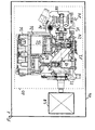
- FIG. 1 shows a schematic representation of a system according to the invention with compressor and hydraulic pump.
- An illustrated system 10 with a compressor 12 and a hydraulic pump 14 is driven by a drive motor 28 of a commercial vehicle 16.
- the compressor 12 comprises a cylinder head 36, a piston chamber 32, piston 30, which are coupled via connecting rods 34 with a crankshaft 18 and move up and down in the interior of the piston chamber 32.
- the crankshaft 18 is mounted on the side facing the drive motor 28 by a ball bearing 22 and extended on the side facing away from the drive motor 28 by an extension 20 over the actual area of the compressor 12 addition.
- a bearing 38 is arranged, which is referred to as a rear compressor bearing.
- the bearing 38 combines two previously necessary in this area bearing each other, which were arranged on both sides of a radial play enabling connection between the crankshaft 18 and extension 20.
- the extension 20 of the crankshaft 18 drives a hydraulic pump 14, which is arranged together with the compressor 12 in a housing 24.
- continuous coolant channels 26 are arranged in the housing 24, via which both the compressor 12 and the hydraulic pump 14 can be cooled.
Landscapes
- Engineering & Computer Science (AREA)
- Mechanical Engineering (AREA)
- General Engineering & Computer Science (AREA)
- Compressor (AREA)
Claims (5)
- Système (10) comprenant un compresseur (12) et une pompe (14) hydraulique à utiliser dans un véhicule (16) utilitaire, le compresseur comprenant un arbre (18) de manivelle pour l'entraînement du compresseur (12) et la pompe (14) hydraulique pouvant être entraînée par un prolongement (20) de l'arbre (18) de manivelle, l'arbre (18) de manivelle étant monté par un roulement (20) à billes, et dans lequel le compresseur (12) et la pompe (14) hydraulique sont intégrés dans une enveloppe (24) commune, caractérisé en ce qu'il est prévu, dans l'enveloppe (24) commune, des canaux (26) dans lesquels passe du fluide de refroidissement et qui refroidissent à la fois le compresseur (12) et la pompe (14) hydraulique.
- Système (10) suivant la revendication 1,
caractérisé en ce que l'arbre (18) de manivelle et le prolongement (20) sont fabriqués d'une seule pièce. - Système (10) suivant la revendication 1 ou la revendication 2,
caractérisé en ce que le roulement (22) à billes est disposé du côté éloigné de la pompe (14) hydraulique. - Procédé de fabrication d'un système (10) comprenant un compresseur (12), une pompe (14) hydraulique à utiliser dans un véhicule (16) utilitaire, le compresseur (12) comprenant un arbre (18) de manivelle pour l'entraînement du compresseur (12), la pompe (14) hydraulique pouvant être entraînée par un prolongement (20) de l'arbre (18) de manivelle et le compresseur (12) et la pompe (14) hydraulique étant intégrés dans une enveloppe (24) commune, l'arbre (18) étant inséré dans l'enveloppe (14) commune par le côté éloigné de la pompe (14) hydraulique, caractérisé en ce que des canaux (26), dans lesquels passe du fluide de refroidissement, sont disposés sur l'enveloppe (24) commune pour le refroidissement du compresseur (12) et de la pompe (14) hydraulique.
- Procédé suivant la revendication 4,
caractérisé en ce qu'un roulement (22) à billes est monté du côté de l'arbre (18) de manivelle éloigné de la pompe (14) hydraulique.
Applications Claiming Priority (2)
| Application Number | Priority Date | Filing Date | Title |
|---|---|---|---|
| DE102008005431A DE102008005431A1 (de) | 2008-01-22 | 2008-01-22 | Kompressor mit Hydraulikpumpe und Verfahren zur Herstellung eines Kompressors mit Hydraulikpumpe |
| PCT/EP2009/000141 WO2009092531A1 (fr) | 2008-01-22 | 2009-01-13 | Compresseur à pompe hydraulique et procédé pour produire un tel compresseur |
Publications (2)
| Publication Number | Publication Date |
|---|---|
| EP2245307A1 EP2245307A1 (fr) | 2010-11-03 |
| EP2245307B1 true EP2245307B1 (fr) | 2013-07-24 |
Family
ID=40497594
Family Applications (1)
| Application Number | Title | Priority Date | Filing Date |
|---|---|---|---|
| EP09703144.7A Not-in-force EP2245307B1 (fr) | 2008-01-22 | 2009-01-13 | Compresseur à pompe hydraulique et procédé pour produire un tel compresseur |
Country Status (6)
| Country | Link |
|---|---|
| EP (1) | EP2245307B1 (fr) |
| CN (1) | CN101896722B (fr) |
| BR (1) | BRPI0906223A8 (fr) |
| DE (1) | DE102008005431A1 (fr) |
| RU (1) | RU2498112C2 (fr) |
| WO (1) | WO2009092531A1 (fr) |
Families Citing this family (2)
| Publication number | Priority date | Publication date | Assignee | Title |
|---|---|---|---|---|
| DE102010024346A1 (de) * | 2010-06-18 | 2011-12-22 | Knorr-Bremse Systeme für Schienenfahrzeuge GmbH | Luftgekühlter Kolbenkompressor mit spezieller Kühlluftführung |
| DE102017011615A1 (de) | 2017-12-15 | 2019-06-19 | Knorr-Bremse Systeme für Nutzfahrzeuge GmbH | Antriebsanordnung für einen Kompressor eines Nutzfahrzeugs |
Family Cites Families (8)
| Publication number | Priority date | Publication date | Assignee | Title |
|---|---|---|---|---|
| DE1145502B (de) * | 1960-01-05 | 1963-03-14 | Westinghouse Bremsen Gmbh | Mit einer Zahnradpumpe gekuppelter Luftverdichter mit hin- und hergehendem Kolben fuer Fahrzeuge, insbesondere Kraftfahrzeuge |
| DE2002470C2 (de) * | 1970-01-21 | 1982-09-09 | Daimler-Benz Ag, 7000 Stuttgart | Anordnung eines Luftpressers an einer Brennkraftmaschine |
| DE3012080A1 (de) * | 1980-03-28 | 1981-10-08 | Wabco Fahrzeugbremsen Gmbh, 3000 Hannover | Aggregat, insbesondere verdichter fuer druckluftanlagen |
| DE3612672A1 (de) | 1986-04-15 | 1987-10-22 | Linde Ag | Mehrwege-schaltarmatur und verfahren zum betreiben derselben |
| DE3616672A1 (de) * | 1986-05-16 | 1987-11-19 | Man Nutzfahrzeuge Gmbh | Nebenantrieb einer brennkraftmaschine fuer mehrere hilfsmaschinen |
| US5497742A (en) | 1994-12-19 | 1996-03-12 | Midland Brake, Inc. | Drive through crankshaft |
| DE102005059491A1 (de) * | 2005-12-13 | 2007-06-14 | Knorr-Bremse Systeme für Nutzfahrzeuge GmbH | Wassergekühlter Kolbenverdichter |
| RU58477U1 (ru) * | 2006-04-20 | 2006-11-27 | Владимир Иванович Кутовой | Установка компрессорная универсальная малогабаритная |
-
2008
- 2008-01-22 DE DE102008005431A patent/DE102008005431A1/de not_active Ceased
-
2009
- 2009-01-13 WO PCT/EP2009/000141 patent/WO2009092531A1/fr not_active Ceased
- 2009-01-13 CN CN200980101339.8A patent/CN101896722B/zh not_active Expired - Fee Related
- 2009-01-13 RU RU2010134934/06A patent/RU2498112C2/ru not_active IP Right Cessation
- 2009-01-13 EP EP09703144.7A patent/EP2245307B1/fr not_active Not-in-force
- 2009-01-13 BR BRPI0906223A patent/BRPI0906223A8/pt not_active IP Right Cessation
Also Published As
| Publication number | Publication date |
|---|---|
| CN101896722B (zh) | 2015-09-16 |
| WO2009092531A1 (fr) | 2009-07-30 |
| RU2010134934A (ru) | 2012-02-27 |
| BRPI0906223A2 (pt) | 2015-07-07 |
| BRPI0906223A8 (pt) | 2015-09-29 |
| CN101896722A (zh) | 2010-11-24 |
| DE102008005431A1 (de) | 2009-07-23 |
| EP2245307A1 (fr) | 2010-11-03 |
| RU2498112C2 (ru) | 2013-11-10 |
Similar Documents
| Publication | Publication Date | Title |
|---|---|---|
| EP2300711B1 (fr) | Système de compresseur servant à l'alimentation en air comprimé d'un véhicule utilitaire, et procédé permettant de faire fonctionner un système de compresseur | |
| EP1998009B1 (fr) | Dispositif de palier | |
| DE102012202460A1 (de) | Elektromotorische Getriebevorrichtung mit einstückigem Gehäuse | |
| DE102010064061A1 (de) | Turboverdichter und Verfahren zur Verdichtung von Gas | |
| DE102010054939A1 (de) | Lageranordnung für einen Turbolader und Turbolader | |
| EP1307657B1 (fr) | Pompe a vide a deux arbres | |
| EP1963674B1 (fr) | Compresseur a piston refroidi par eau | |
| DE102010013702A1 (de) | Turbine, Abgasturbolader, Kraftfahrzeug und Verfahren zur Montage einer derartigen Turbine | |
| DE102011051401B4 (de) | Kompakte, fluidbetätigte universalkupplung | |
| DE102014117081A1 (de) | Ölpumpe für automatikgetriebe | |
| EP3372552A1 (fr) | Moteur électrique comprenant un frein d'arrêt intégré | |
| EP2245307B1 (fr) | Compresseur à pompe hydraulique et procédé pour produire un tel compresseur | |
| DE69212118T2 (de) | Rotierende Geräte | |
| EP3494290B1 (fr) | Ensemble de couvercle de soupape et son procédö de mise en oeuvre | |
| DE102009053101B4 (de) | Turbolader mit einem Turboladergehäuse und einer Aufnahmeeinrichtung für das Laufzeug des Turboladers | |
| EP0814268B1 (fr) | Ensemble modulaire pour la fabrication d'une pompe, en particulier d'une pompe entraínée par une accouplement magnétique | |
| DE102015105543A1 (de) | Getriebekühlung | |
| DE10124560B4 (de) | Kreiskolbenmotor | |
| DE102014208867A1 (de) | Integration einer Elektromotoreneinheit in ein Getriebegehäuse | |
| DE102012218075A1 (de) | Hochdruckpumpe, insbesondere Kraftstoffhochdruckpumpe | |
| DE102019133322A1 (de) | Antrieb mit einer Rotorwelleninnenkühlung eines Elektromotors sowie ein Kraftfahrzeug mit einem solchen Antrieb | |
| DE102007062290A1 (de) | Kompressor einer Fahrzeugklimaanlage | |
| WO2007003654A1 (fr) | Element de carter de moteur et carter de moteur pour moteurs a combustion d'automobiles | |
| DE102008013677A1 (de) | Kühlmediumpumpe | |
| DE102005057709A1 (de) | Brennkraftmaschine mit einem am Zylinderblock angeordneten Nebenaggregateträger |
Legal Events
| Date | Code | Title | Description |
|---|---|---|---|
| PUAI | Public reference made under article 153(3) epc to a published international application that has entered the european phase |
Free format text: ORIGINAL CODE: 0009012 |
|
| 17P | Request for examination filed |
Effective date: 20100823 |
|
| AK | Designated contracting states |
Kind code of ref document: A1 Designated state(s): AT BE BG CH CY CZ DE DK EE ES FI FR GB GR HR HU IE IS IT LI LT LU LV MC MK MT NL NO PL PT RO SE SI SK TR |
|
| AX | Request for extension of the european patent |
Extension state: AL BA RS |
|
| DAX | Request for extension of the european patent (deleted) | ||
| 17Q | First examination report despatched |
Effective date: 20110503 |
|
| GRAP | Despatch of communication of intention to grant a patent |
Free format text: ORIGINAL CODE: EPIDOSNIGR1 |
|
| GRAS | Grant fee paid |
Free format text: ORIGINAL CODE: EPIDOSNIGR3 |
|
| GRAA | (expected) grant |
Free format text: ORIGINAL CODE: 0009210 |
|
| AK | Designated contracting states |
Kind code of ref document: B1 Designated state(s): AT BE BG CH CY CZ DE DK EE ES FI FR GB GR HR HU IE IS IT LI LT LU LV MC MK MT NL NO PL PT RO SE SI SK TR |
|
| REG | Reference to a national code |
Ref country code: GB Ref legal event code: FG4D Free format text: NOT ENGLISH |
|
| REG | Reference to a national code |
Ref country code: CH Ref legal event code: EP |
|
| REG | Reference to a national code |
Ref country code: AT Ref legal event code: REF Ref document number: 623629 Country of ref document: AT Kind code of ref document: T Effective date: 20130815 |
|
| REG | Reference to a national code |
Ref country code: IE Ref legal event code: FG4D Free format text: LANGUAGE OF EP DOCUMENT: GERMAN |
|
| REG | Reference to a national code |
Ref country code: DE Ref legal event code: R096 Ref document number: 502009007636 Country of ref document: DE Effective date: 20130919 |
|
| REG | Reference to a national code |
Ref country code: SE Ref legal event code: TRGR |
|
| REG | Reference to a national code |
Ref country code: NL Ref legal event code: VDEP Effective date: 20130724 |
|
| REG | Reference to a national code |
Ref country code: LT Ref legal event code: MG4D |
|
| PG25 | Lapsed in a contracting state [announced via postgrant information from national office to epo] |
Ref country code: CY Free format text: LAPSE BECAUSE OF FAILURE TO SUBMIT A TRANSLATION OF THE DESCRIPTION OR TO PAY THE FEE WITHIN THE PRESCRIBED TIME-LIMIT Effective date: 20130710 Ref country code: LT Free format text: LAPSE BECAUSE OF FAILURE TO SUBMIT A TRANSLATION OF THE DESCRIPTION OR TO PAY THE FEE WITHIN THE PRESCRIBED TIME-LIMIT Effective date: 20130724 Ref country code: HR Free format text: LAPSE BECAUSE OF FAILURE TO SUBMIT A TRANSLATION OF THE DESCRIPTION OR TO PAY THE FEE WITHIN THE PRESCRIBED TIME-LIMIT Effective date: 20130724 Ref country code: NO Free format text: LAPSE BECAUSE OF FAILURE TO SUBMIT A TRANSLATION OF THE DESCRIPTION OR TO PAY THE FEE WITHIN THE PRESCRIBED TIME-LIMIT Effective date: 20131024 Ref country code: IS Free format text: LAPSE BECAUSE OF FAILURE TO SUBMIT A TRANSLATION OF THE DESCRIPTION OR TO PAY THE FEE WITHIN THE PRESCRIBED TIME-LIMIT Effective date: 20131124 Ref country code: PT Free format text: LAPSE BECAUSE OF FAILURE TO SUBMIT A TRANSLATION OF THE DESCRIPTION OR TO PAY THE FEE WITHIN THE PRESCRIBED TIME-LIMIT Effective date: 20131125 |
|
| PG25 | Lapsed in a contracting state [announced via postgrant information from national office to epo] |
Ref country code: GR Free format text: LAPSE BECAUSE OF FAILURE TO SUBMIT A TRANSLATION OF THE DESCRIPTION OR TO PAY THE FEE WITHIN THE PRESCRIBED TIME-LIMIT Effective date: 20131025 Ref country code: FI Free format text: LAPSE BECAUSE OF FAILURE TO SUBMIT A TRANSLATION OF THE DESCRIPTION OR TO PAY THE FEE WITHIN THE PRESCRIBED TIME-LIMIT Effective date: 20130724 Ref country code: LV Free format text: LAPSE BECAUSE OF FAILURE TO SUBMIT A TRANSLATION OF THE DESCRIPTION OR TO PAY THE FEE WITHIN THE PRESCRIBED TIME-LIMIT Effective date: 20130724 Ref country code: NL Free format text: LAPSE BECAUSE OF FAILURE TO SUBMIT A TRANSLATION OF THE DESCRIPTION OR TO PAY THE FEE WITHIN THE PRESCRIBED TIME-LIMIT Effective date: 20130724 Ref country code: SI Free format text: LAPSE BECAUSE OF FAILURE TO SUBMIT A TRANSLATION OF THE DESCRIPTION OR TO PAY THE FEE WITHIN THE PRESCRIBED TIME-LIMIT Effective date: 20130724 Ref country code: PL Free format text: LAPSE BECAUSE OF FAILURE TO SUBMIT A TRANSLATION OF THE DESCRIPTION OR TO PAY THE FEE WITHIN THE PRESCRIBED TIME-LIMIT Effective date: 20130724 |
|
| PG25 | Lapsed in a contracting state [announced via postgrant information from national office to epo] |
Ref country code: CY Free format text: LAPSE BECAUSE OF FAILURE TO SUBMIT A TRANSLATION OF THE DESCRIPTION OR TO PAY THE FEE WITHIN THE PRESCRIBED TIME-LIMIT Effective date: 20130724 |
|
| PG25 | Lapsed in a contracting state [announced via postgrant information from national office to epo] |
Ref country code: SK Free format text: LAPSE BECAUSE OF FAILURE TO SUBMIT A TRANSLATION OF THE DESCRIPTION OR TO PAY THE FEE WITHIN THE PRESCRIBED TIME-LIMIT Effective date: 20130724 Ref country code: DK Free format text: LAPSE BECAUSE OF FAILURE TO SUBMIT A TRANSLATION OF THE DESCRIPTION OR TO PAY THE FEE WITHIN THE PRESCRIBED TIME-LIMIT Effective date: 20130724 Ref country code: EE Free format text: LAPSE BECAUSE OF FAILURE TO SUBMIT A TRANSLATION OF THE DESCRIPTION OR TO PAY THE FEE WITHIN THE PRESCRIBED TIME-LIMIT Effective date: 20130724 Ref country code: RO Free format text: LAPSE BECAUSE OF FAILURE TO SUBMIT A TRANSLATION OF THE DESCRIPTION OR TO PAY THE FEE WITHIN THE PRESCRIBED TIME-LIMIT Effective date: 20130724 Ref country code: CZ Free format text: LAPSE BECAUSE OF FAILURE TO SUBMIT A TRANSLATION OF THE DESCRIPTION OR TO PAY THE FEE WITHIN THE PRESCRIBED TIME-LIMIT Effective date: 20130724 |
|
| PG25 | Lapsed in a contracting state [announced via postgrant information from national office to epo] |
Ref country code: ES Free format text: LAPSE BECAUSE OF FAILURE TO SUBMIT A TRANSLATION OF THE DESCRIPTION OR TO PAY THE FEE WITHIN THE PRESCRIBED TIME-LIMIT Effective date: 20130724 |
|
| PLBE | No opposition filed within time limit |
Free format text: ORIGINAL CODE: 0009261 |
|
| STAA | Information on the status of an ep patent application or granted ep patent |
Free format text: STATUS: NO OPPOSITION FILED WITHIN TIME LIMIT |
|
| 26N | No opposition filed |
Effective date: 20140425 |
|
| BERE | Be: lapsed |
Owner name: KNORR-BREMSE SYSTEME FUR NUTZFAHRZEUGE G.M.B.H. Effective date: 20140131 |
|
| REG | Reference to a national code |
Ref country code: DE Ref legal event code: R097 Ref document number: 502009007636 Country of ref document: DE Effective date: 20140425 |
|
| PG25 | Lapsed in a contracting state [announced via postgrant information from national office to epo] |
Ref country code: MC Free format text: LAPSE BECAUSE OF FAILURE TO SUBMIT A TRANSLATION OF THE DESCRIPTION OR TO PAY THE FEE WITHIN THE PRESCRIBED TIME-LIMIT Effective date: 20130724 Ref country code: LU Free format text: LAPSE BECAUSE OF FAILURE TO SUBMIT A TRANSLATION OF THE DESCRIPTION OR TO PAY THE FEE WITHIN THE PRESCRIBED TIME-LIMIT Effective date: 20140113 |
|
| REG | Reference to a national code |
Ref country code: CH Ref legal event code: PL |
|
| GBPC | Gb: european patent ceased through non-payment of renewal fee |
Effective date: 20140113 |
|
| PG25 | Lapsed in a contracting state [announced via postgrant information from national office to epo] |
Ref country code: CH Free format text: LAPSE BECAUSE OF NON-PAYMENT OF DUE FEES Effective date: 20140131 Ref country code: LI Free format text: LAPSE BECAUSE OF NON-PAYMENT OF DUE FEES Effective date: 20140131 |
|
| REG | Reference to a national code |
Ref country code: IE Ref legal event code: MM4A |
|
| PG25 | Lapsed in a contracting state [announced via postgrant information from national office to epo] |
Ref country code: GB Free format text: LAPSE BECAUSE OF NON-PAYMENT OF DUE FEES Effective date: 20140113 |
|
| PG25 | Lapsed in a contracting state [announced via postgrant information from national office to epo] |
Ref country code: IE Free format text: LAPSE BECAUSE OF NON-PAYMENT OF DUE FEES Effective date: 20140113 Ref country code: BE Free format text: LAPSE BECAUSE OF NON-PAYMENT OF DUE FEES Effective date: 20140131 |
|
| REG | Reference to a national code |
Ref country code: AT Ref legal event code: MM01 Ref document number: 623629 Country of ref document: AT Kind code of ref document: T Effective date: 20140113 |
|
| PG25 | Lapsed in a contracting state [announced via postgrant information from national office to epo] |
Ref country code: AT Free format text: LAPSE BECAUSE OF NON-PAYMENT OF DUE FEES Effective date: 20140113 |
|
| REG | Reference to a national code |
Ref country code: FR Ref legal event code: PLFP Year of fee payment: 8 |
|
| PG25 | Lapsed in a contracting state [announced via postgrant information from national office to epo] |
Ref country code: MT Free format text: LAPSE BECAUSE OF FAILURE TO SUBMIT A TRANSLATION OF THE DESCRIPTION OR TO PAY THE FEE WITHIN THE PRESCRIBED TIME-LIMIT Effective date: 20130724 |
|
| PGFP | Annual fee paid to national office [announced via postgrant information from national office to epo] |
Ref country code: IT Payment date: 20160122 Year of fee payment: 8 |
|
| PG25 | Lapsed in a contracting state [announced via postgrant information from national office to epo] |
Ref country code: BG Free format text: LAPSE BECAUSE OF FAILURE TO SUBMIT A TRANSLATION OF THE DESCRIPTION OR TO PAY THE FEE WITHIN THE PRESCRIBED TIME-LIMIT Effective date: 20130724 |
|
| PGFP | Annual fee paid to national office [announced via postgrant information from national office to epo] |
Ref country code: FR Payment date: 20160121 Year of fee payment: 8 Ref country code: SE Payment date: 20160121 Year of fee payment: 8 |
|
| PG25 | Lapsed in a contracting state [announced via postgrant information from national office to epo] |
Ref country code: HU Free format text: LAPSE BECAUSE OF FAILURE TO SUBMIT A TRANSLATION OF THE DESCRIPTION OR TO PAY THE FEE WITHIN THE PRESCRIBED TIME-LIMIT; INVALID AB INITIO Effective date: 20090113 Ref country code: TR Free format text: LAPSE BECAUSE OF FAILURE TO SUBMIT A TRANSLATION OF THE DESCRIPTION OR TO PAY THE FEE WITHIN THE PRESCRIBED TIME-LIMIT Effective date: 20130724 |
|
| REG | Reference to a national code |
Ref country code: FR Ref legal event code: ST Effective date: 20170929 |
|
| PG25 | Lapsed in a contracting state [announced via postgrant information from national office to epo] |
Ref country code: FR Free format text: LAPSE BECAUSE OF NON-PAYMENT OF DUE FEES Effective date: 20170131 |
|
| PG25 | Lapsed in a contracting state [announced via postgrant information from national office to epo] |
Ref country code: SE Free format text: LAPSE BECAUSE OF NON-PAYMENT OF DUE FEES Effective date: 20170114 |
|
| PG25 | Lapsed in a contracting state [announced via postgrant information from national office to epo] |
Ref country code: IT Free format text: LAPSE BECAUSE OF NON-PAYMENT OF DUE FEES Effective date: 20170113 |
|
| PG25 | Lapsed in a contracting state [announced via postgrant information from national office to epo] |
Ref country code: MK Free format text: LAPSE BECAUSE OF FAILURE TO SUBMIT A TRANSLATION OF THE DESCRIPTION OR TO PAY THE FEE WITHIN THE PRESCRIBED TIME-LIMIT Effective date: 20130724 |
|
| PGFP | Annual fee paid to national office [announced via postgrant information from national office to epo] |
Ref country code: DE Payment date: 20200123 Year of fee payment: 12 |
|
| REG | Reference to a national code |
Ref country code: DE Ref legal event code: R119 Ref document number: 502009007636 Country of ref document: DE |
|
| PG25 | Lapsed in a contracting state [announced via postgrant information from national office to epo] |
Ref country code: DE Free format text: LAPSE BECAUSE OF NON-PAYMENT OF DUE FEES Effective date: 20210803 |