EP2245426B1 - Messeinheit für Sagnac-Glasfaserstromsensor - Google Patents
Messeinheit für Sagnac-Glasfaserstromsensor Download PDFInfo
- Publication number
- EP2245426B1 EP2245426B1 EP09713616.2A EP09713616A EP2245426B1 EP 2245426 B1 EP2245426 B1 EP 2245426B1 EP 09713616 A EP09713616 A EP 09713616A EP 2245426 B1 EP2245426 B1 EP 2245426B1
- Authority
- EP
- European Patent Office
- Prior art keywords
- sensing unit
- loops
- sensing
- current
- conductor
- Prior art date
- Legal status (The legal status is an assumption and is not a legal conclusion. Google has not performed a legal analysis and makes no representation as to the accuracy of the status listed.)
- Active
Links
Images


Classifications
-
- G—PHYSICS
- G01—MEASURING; TESTING
- G01R—MEASURING ELECTRIC VARIABLES; MEASURING MAGNETIC VARIABLES
- G01R15/00—Details of measuring arrangements of the types provided for in groups G01R17/00 - G01R29/00, G01R33/00 - G01R33/26 or G01R35/00
- G01R15/14—Adaptations providing voltage or current isolation, e.g. for high-voltage or high-current networks
- G01R15/24—Adaptations providing voltage or current isolation, e.g. for high-voltage or high-current networks using light-modulating devices
- G01R15/245—Adaptations providing voltage or current isolation, e.g. for high-voltage or high-current networks using light-modulating devices using magneto-optical modulators, e.g. based on the Faraday or Cotton-Mouton effect
Definitions
- This invention relates to a sensing unit for use in a Sagnac interferometer optical fibre current sensor and, in an alternative embodiment, to a current sensor incorporating the sensing unit.
- Sagnac interferometer optical fibre current sensors of various types are well known.
- United States Patent 5,677,622 granted to the University of Sydney as assignee of Ian G. Clarke discloses one such current sensor and it comprises a single sensing coil of spun single mode birefringent ("Hi-Bi") optical fibre that is in use located about a current conductor, typically a large-current carrying busbar.
- Hi-Bi spun single mode birefringent
- Counter-propagating light beams are launched into the coil by way of a 3x3 coupler and a measure of the magnitude of current flow is detected as the phase shift between polarisation modes of the counter-propagated light beams.
- WO 00/36425 A2 discloses an interferometric sensor having an optic fiber which forms a sensing loop optical path and a second loop that is wound in the opposite direction of the sensor loop.
- WO 01/63302 A2 discloses a Faraday-type current sensor which is less susceptive to effects caused by rotation, acceleration and vibration of the sensor coil.
- the present invention in its primary form seeks to provide a sensing unit with a sensing coil winding that facilitates nullification, or at least partial nullification, of the effects of rotational movement; that is, a sensing coil that provides for minimal sensitivity to rotational movement.
- the invention provides a sensing unit for a Sagnac interferometer current sensor according to claim 1.
- Advantageous embodiments are defined by the dependent claims.
- the sensing coils in accordance with the (various) described embodiments may optionally be wound with their loops inclined to one another (i.e., separated by an angle other than 0 or 180 degrees) but, for optimum performance, the loops forming the respective coils desirably are disposed substantially in a common plane.
- the invention in one of its embodiments may be further defined as providing a sensing unit for a Sagnac interferometer current sensor and which is connectable in circuit with a current busbar.
- the sensing unit comprises:
- the sensing unit as defined in claim 1 has the current conductor portions and the sensing coil loops arranged and disposed such that, when the sensing unit is connected in circuit with a current-carrying busbar, the two conductor portions of the current conductor provide effectively for increased current sensitivity whilst the dual-loop sensing coil provides for minimal sensitivity to rotational movement.
- the sensing unit may be incorporated in a current sensor and, thus, the invention may be defined still further as providing a Sagnac interferometer current sensor comprising: a sensing unit as above defined, a light source, a coupler interconnecting the light source and the sensing coil and arranged to launch counter-propagating light beams into the sensing coil, and a detector for detecting phase shift between polarisation modes of the counter-propagating light beams.
- a Sagnac interferometer current sensor comprising: a sensing unit as above defined, a light source, a coupler interconnecting the light source and the sensing coil and arranged to launch counter-propagating light beams into the sensing coil, and a detector for detecting phase shift between polarisation modes of the counter-propagating light beams.
- the carrier in one embodiment of the sensing unit may optionally comprise first and second spaced-apart conductor members which are connectable in series with the busbar and which respectively are secured to the first and second conductor portions.
- the first and second conductor portions may be formed as projections (for example, solid cylindrical projections) of a common plate portion of the carrier and, in this embodiment of the invention, the sensing coil may be carried between the conductor members and the common plate.
- Insulating gaskets may be provided between various ones of the sensing unit components so that a series circuit is formed between the first and second conductor members by way of the first (cylindrical) conductor portion, the common plate and the second (cylindrical) conductor portion.
- the current sensor comprises, in general, a processor 10 in which optical signals are generated, received and processed to provide a measure of sensed electrical current flow through a two-part conductor 11 / 12, and a sensing unit 13.
- the sensing unit 13 comprises a sensing coil 14 having two interconnected loops 15 and 16 which enclose the respective conductor portions 11 and 12.
- the two loops 15 and 16 of the sensing coil 14 are located substantially in a common plane, and the two conductor portions 11 and 12, which have spaced-apart parallel axes, extend orthogonally through the respective loops 15 and 16.
- the sensing coil 14 is connected to an optical source 17 and to an optical detector 18 of the processor 10 by way of a length of duplex single mode optical fibre 19 and further by way of a multiplexing network 20 and a 3x3 optical coupler 21.
- These components 17 to 20 in their various possible forms are well known in the context of Sagnac interferometers, including Sagnac optical fibre current sensors, and, therefore, are not described herein in any detail.
- the optical source 17 desirably is selected to comprise a super-luminescent diode which is pulsed to provide an output in the form of a series of optical pulses at a frequency of 50 to 200 kHz, with a pulse width of 100 to 200 ns.
- the output from the optical source 17 is launched into the multiplexing network 20, which splits the input pulses three ways, separates them in time with optical delay lines and then launches the pulses into the 3x3 coupler 21, one pulse per arm.
- the multiplexing network 20 is arranged also to gather optical pulses which are returned from the sensing coil and output from the 3x3 coupler.
- the multiplexing network again separates the pulses in time, using delay lines, and multiplexes the pulses to provide a single (pulsed) input signal to the optical detector 18 by way of the optical fibre connection 19.
- the optical detector 18 converts incoming optical pulses to electronic pulses, and a signal processing system 22 is provided to determine the amplitude of each of the pulses as a measure of electrical current flowing through the conductor portions 11 and 12.
- the multiplexing network 20 splits each optical pulse from the optical source 17 into three pulses which are separated in time and launched sequentially into the arms of the 3x3 coupler 21, this producing one optical pulse output from each arm of the 3x3 coupler for each input pulse. This in turn produces nine output pulses (i.e., 3 input pulses x 3 arms) which are multiplexed into the "output" fibre 19. These output pulses are represented by the term I nm where:
- I 32 represents the intensity of the optical signal from arm 2 resulting from input to arm 3.
- the sensing coil 14 as shown in Figures 1 and 2 is wound in a figure-of-eight pattern and, thus, is formed such that light that is launched into the first loop 15 in a manner to propagate in a first direction (e.g., counter-clockwise, as indicated by arrows 23) will propagate in a second, opposite (clockwise, as indicated by arrows 24), direction in the interconnected second loop 16.
- a first direction e.g., counter-clockwise, as indicated by arrows 23
- second, opposite clockwise, as indicated by arrows 24
- each loop 15 and 16 of the coil 14 are both shown, for illustrative convenience, as comprising a single turn of optical fibre; depending upon the level of sensitivity required in a given current sensor, each loop might typically comprise between 1 and 100 turns, or more for special purposes.
- the nominal diameter of each of the loops 15 and 16 might typically be of the order of 100 mm but, again depending upon the requirements of a given current sensor, may be as large as 600 mm or more.
- the optical fibre from which the coil 14 is formed may comprise any optical fibre that provides for transmission of a single elliptical polarisation state or which is arranged in use to transmit a single elliptical polarisation state.
- it might typically comprise spun polarising fibre that incorporates boron-doped bow-tie regions to create stress birefringence.
- the sensing coil 14 is shown to be wound in Figures 1 and 2 is particularly appropriate when the current conductor comprises the two portions or legs 11 and 12 through which the current is conducted (into the drawing, as illustrated, in the case of conductor portion 11 and out of the drawing in the case of conductor portion 12).
- the sensing coil 14 may, for example, be wound with two quasi-concentric loops 26 and 27, as shown in Figure 3 . In this case the number of turns forming, and the areas enclosed by, the two (first and second) loops would need satisfy the above mentioned relationship (1).
- the sensing coil as shown in Figure 4 may comprise a first loop 28, that is formed to enclose the single current conductor 25, and further loops wound as interconnected sub-loops 29 located about the perimeter of the first loop 28.
- the sensing coil will be wound in a manner such that light propagating in a first direction (e.g., counter-clockwise, as indicated by arrows 30) in the first loop will be caused to propagate in the opposite (clockwise, as indicated by arrows 31) direction in each of the sub-loops 29.
- a current sensor may be constructed in various ways, depending, for example, on whether the current conductor comprises two series connected portions 11 and 12, as shown in Figures 1 and 2 , or a single leg 25 as shown in figures 3 and 4 .
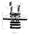
- One possible embodiment of the current sensor may incorporate a sensing unit 13, that is arranged to carry a figure-of-eight sensing coil (as illustrated in Figures 1 and 2 ), as shown in Figure 5 .
- the sensing unit 13 as shown in Figure 5 comprises a carrier 32 for the sensing coil 14, and the carrier comprises first and second spaced-apart bar-shaped conductor members 33 and 34 which are connectable in series with a current-carrying busbar (not shown).
- the conductor members 33 and 34 are secured by screws 35 to the first and second conductor portions 11 and 12 and, in the illustrated embodiment, the first and second conductor portions are formed as solid cylindrical projections 36 and 37 of a common disc-shaped plate portion 38 of the carrier 32.
- the sensing coil 14 is carried between the conductor members 33,34 and the common plate 38 and the sensing coil is positioned so that its loops 15 and 16 enclose (i.e., encircle) the cylindrical projections 36 and 37.
- An insulating gasket 39 is provided between the conductor members 33,34 and the sensing coil, and a further insulating gasket 40 is provided between the conductor members 33, 34 and clamping plates 41 and 42.
- Screws 43 are provided to clamp the carrier components together, and a cap 44 (through which optical fibre connections are made to the sensing coil) is removably attached to the plate portion 38 by way of bayonet connections.
- a series circuit is formed between the first and second conductor members 33 and 34 by way of the first (cylindrical) conductor portion 36, the common plate 38 and the second (cylindrical) conductor portion 37.
Landscapes
- Engineering & Computer Science (AREA)
- Power Engineering (AREA)
- Physics & Mathematics (AREA)
- General Physics & Mathematics (AREA)
- Measuring Instrument Details And Bridges, And Automatic Balancing Devices (AREA)
Claims (10)
- Messeinheit (13) für einen Sagnac-Interferometer-Stromsensor, die Messeinheit (13) umfassend:eine Messspule (14) gebildet aus einer optischen Faser (19), die bei Anwendung dazu ausgebildet ist, dass sie einen einzelnen elliptischen Polarisationszustand überträgt, und wobei die Messspule (14) eine erste und eine zweite Schleife (15, 16) umfasst, wobei die erste und die zweite Schleife (15, 16) derart miteinander verbunden sind, dass Licht, das sich in der ersten Schleife (15) in eine erste Richtung ausbreitet, sich in der zweiten Schleife (16) in eine zweite, entgegengesetzte Richtung ausbreitet,wobei die erste und die zweite Schleife (15, 16) mit Windungen und umschlossenen Bereichen gewunden sind, die die Bedingung erfüllen: N1xA1 = N2xA2, worin N1 = die Anzahl an Windungen in der ersten Schleife, A1 = den von der ersten Schleife umschlossenen Bereich, N2 = die Anzahl an Windungen in der zweiten Schleife und A2 = den von der zweiten Schleife umschlossenen Bereich bezeichnet, undeinen Träger mit einem ersten und einem zweiten Stromleiterabschnitt (11, 12),dadurch gekennzeichnet, dassder erste und der zweite Stromleiterabschnitt (11, 12) derart ausgebildet sind, dass ein Stromfluss wirksam in entgegengesetzte Richtungen durch den ersten und den zweiten Leiterabschnitt (11, 12) erfolgt, und dadurch, dassdie erste und die zweite miteinander verbundenen Schleifen (15, 16) dazu ausgebildet sind, dass sie die zugehörigen ersten und zweiten Stromleiterabschnitte (11, 12) umschließen.
- Messeinheit (13) nach Anspruch 1, bei der die erste und die zweite Schleife (15, 16) der Messspule (14) mit im Wesentlichen der gleichen Anzahl an Windungen ausgebildet sind und Bereiche von im Wesentlichen gleicher Größe umschließen.
- Messeinheit (13) nach Anspruch 1 oder 2, bei der die einzelnen Schleifen (15, 16) der Messspule (14) um räumlich getrennte parallele Achsen gewunden sind.
- Messeinheit (13) nach einem der vorhergehenden Ansprüche, bei der die erste und die zweite Schleife (15, 16) der Messspule (14) eine Windung in Form einer Acht ausbilden, wobei die einzelnen Schleifen (15, 16) um räumlich getrennte parallele Achsen gewunden sind.
- Messeinheit (13) nach einem der vorhergehenden Ansprüche, bei der die einzelnen Schleifen (15, 16) der Messspule (14) im Wesentlichen in einer gemeinsamen Ebene liegen.
- Messeinheit (13) nach einem der vorhergehenden Ansprüche, bei der die Messeinheit (13) mit einer Stromsammelschiene in einer Schaltung verbindbar ist, wobei der erste und der zweite Leiterabschnitt (11, 12) des Trägers bei Anwendung dazu ausgebildet sind, dass sie mit der Stromsammelschiene seriell verbunden werden.
- Messeinheit (13) nach Anspruch 6, bei der der Träger ein erstes und ein zweites beabstandetes Leiterelement umfasst, die mit der Stromsammelschiene seriell verbindbar sind, und die entsprechend an dem ersten und dem zweiten Leiterabschnitt (11, 12) befestigt sind.
- Messeinheit (13) nach Anspruch 7, bei der der erste und der zweite Leiterabschnitt (11, 12) als Vorsprünge eines gemeinsamen Plattenabschnitts des Trägers ausgebildet sind, und die Messspule (14) zwischen den Leiterelementen und dem gemeinsamen Plattenabschnitt getragen ist.
- Messeinheit (13) nach Anspruch 8, bei der Isolierdichtungen zwischen den Komponenten der Messeinheit (13) angeordnet sind, wobei über den ersten Leiterabschnitt, den gemeinsamen Plattenabschnitt und den zweiten Leiterabschnitt eine serielle Schaltung zwischen dem ersten und dem zweiten Leiterelement ausgebildet ist.
- Sagnac-Interferometer-Stromsensor, umfassend:eine Messeinheit (13) nach einem der vorhergehenden Ansprüche,eine Lichtquelle (17),einen Koppler (21), der die Lichtquelle und die Messspule (14) miteinander verbindet und dazu ausgebildet ist, dass er sich gegenläufig ausbreitende Lichtstrahlen in die Messspule (14) aussendet, undeinen Detektor (18) zum Detektieren einer Phasenverschiebung zwischen Polarisationsmoden der sich gegenläufig ausbreitenden Lichtstrahlen.
Applications Claiming Priority (3)
| Application Number | Priority Date | Filing Date | Title |
|---|---|---|---|
| AU2008900845A AU2008900845A0 (en) | 2008-02-22 | Sagnac optical fibre current sensor and sensing unit therefor | |
| AU2008900844A AU2008900844A0 (en) | 2008-02-22 | Sagnac optical fibre current sensor and sensing coil therefor | |
| PCT/AU2009/000200 WO2009103126A1 (en) | 2008-02-22 | 2009-02-20 | Sensing coil and sensing unit for sagnac optical fibre current sensor |
Publications (3)
| Publication Number | Publication Date |
|---|---|
| EP2245426A1 EP2245426A1 (de) | 2010-11-03 |
| EP2245426A4 EP2245426A4 (de) | 2012-10-31 |
| EP2245426B1 true EP2245426B1 (de) | 2014-08-27 |
Family
ID=40985006
Family Applications (1)
| Application Number | Title | Priority Date | Filing Date |
|---|---|---|---|
| EP09713616.2A Active EP2245426B1 (de) | 2008-02-22 | 2009-02-20 | Messeinheit für Sagnac-Glasfaserstromsensor |
Country Status (8)
| Country | Link |
|---|---|
| US (1) | US8542366B2 (de) |
| EP (1) | EP2245426B1 (de) |
| CN (1) | CN101952686B (de) |
| AU (1) | AU2009217236B2 (de) |
| CA (1) | CA2715656C (de) |
| ES (1) | ES2524790T3 (de) |
| NZ (1) | NZ587618A (de) |
| WO (1) | WO2009103126A1 (de) |
Families Citing this family (15)
| Publication number | Priority date | Publication date | Assignee | Title |
|---|---|---|---|---|
| CN103163351B (zh) * | 2011-12-13 | 2015-08-05 | 北京航天时代光电科技有限公司 | 一种三相共用光源的光学电压传感器 |
| CN102539873B (zh) * | 2012-01-10 | 2013-12-25 | 中国科学院西安光学精密机械研究所 | 光纤电流传感器线圈及光纤电流传感器 |
| CN103207301A (zh) * | 2012-01-16 | 2013-07-17 | 中国科学院西安光学精密机械研究所 | 一种光纤电流传感器线圈及基于该线圈的光纤电流传感器 |
| CN103063898B (zh) * | 2012-12-20 | 2015-11-18 | 中国科学院西安光学精密机械研究所 | 一种传感光纤环以及全光纤电流互感器 |
| PL3043189T3 (pl) | 2013-09-04 | 2018-03-30 | Arteche Centro De Tecnologia, A.I.E. | System optyczny do identyfikowania usterek w mieszanych elektroenergetycznych liniach przesyłowych |
| RU2677990C2 (ru) * | 2014-08-19 | 2019-01-22 | Абб Швайц Аг | Оптический датчик с двулучепреломляющим измерительным spun-волокном |
| US20160084731A1 (en) * | 2014-09-22 | 2016-03-24 | The Cleveland Electric Laboratories Company | Acoustic transducer apparatus and method of use |
| CN107250814A (zh) | 2015-01-16 | 2017-10-13 | 西门子公司 | 光电测量装置和测量电流的方法 |
| KR102442423B1 (ko) * | 2015-05-20 | 2022-09-13 | 주식회사 레인보우코퍼레이션 | Rf 센서 장치 |
| ES2980502T3 (es) * | 2019-09-25 | 2024-10-01 | Lumiker Aplicaciones Tecnologicas S L | Equipo de medida de corriente basado en fibra óptica para medir la corriente que circula por un conductor, y método asociado |
| US11789043B2 (en) | 2019-09-25 | 2023-10-17 | Lumiker Aplicaciones Tecnológicas S.L. | Method and apparatus for measuring the current circulating through a conductor |
| US11913785B2 (en) | 2020-04-17 | 2024-02-27 | Huvr, Inc. | Extended reach ring interferometer with at least two broadband light sources and signal antifading topology for event detection, location and characterization |
| DE102020124516A1 (de) * | 2020-09-21 | 2022-03-24 | Turck Duotec GmbH | Sensor mit Lichtleiteranschluss |
| CA3229819A1 (en) * | 2021-09-03 | 2023-03-09 | Matar Mamdouh | Passive optical sagnac interferometer for current sensing |
| WO2023158334A1 (ru) * | 2022-02-15 | 2023-08-24 | Общество с ограниченной ответственностью "Научно-Производственный центр "Профотек" | Волоконно-оптический чувствительный элемент датчика электрического тока и магнитного поля |
Family Cites Families (6)
| Publication number | Priority date | Publication date | Assignee | Title |
|---|---|---|---|---|
| US5074665A (en) * | 1989-12-21 | 1991-12-24 | Andrew Corporation | Fiber optic gyroscope using dual-section counter-wound coil |
| US5677622A (en) * | 1991-12-24 | 1997-10-14 | The University Of Sydney | Current sensor using a Sagnac interferometer and spun, single mode birefringent optical fiber to detect current via the Faraday effect |
| US6301400B1 (en) * | 1998-11-12 | 2001-10-09 | Nxtphase Technologies Srl | Fiber optic current sensor having rotation immunity |
| US6703821B2 (en) * | 2000-02-28 | 2004-03-09 | Kvh Industries, Inc. | Faraday-effect current sensor with improved vibration response |
| WO2003023320A1 (en) | 2001-09-10 | 2003-03-20 | The University Of Sydney | Suppressed drift interferometer |
| JP2003227851A (ja) | 2002-02-01 | 2003-08-15 | Toshiba Corp | 光電流センサ |
-
2009
- 2009-02-20 CN CN200980106131.5A patent/CN101952686B/zh active Active
- 2009-02-20 CA CA2715656A patent/CA2715656C/en active Active
- 2009-02-20 AU AU2009217236A patent/AU2009217236B2/en active Active
- 2009-02-20 NZ NZ587618A patent/NZ587618A/xx unknown
- 2009-02-20 ES ES09713616.2T patent/ES2524790T3/es active Active
- 2009-02-20 EP EP09713616.2A patent/EP2245426B1/de active Active
- 2009-02-20 WO PCT/AU2009/000200 patent/WO2009103126A1/en not_active Ceased
- 2009-02-20 US US12/918,273 patent/US8542366B2/en active Active
Also Published As
| Publication number | Publication date |
|---|---|
| EP2245426A4 (de) | 2012-10-31 |
| US20110051145A1 (en) | 2011-03-03 |
| CA2715656C (en) | 2017-07-11 |
| CA2715656A1 (en) | 2009-08-27 |
| AU2009217236A1 (en) | 2009-08-27 |
| CN101952686A (zh) | 2011-01-19 |
| NZ587618A (en) | 2013-09-27 |
| CN101952686B (zh) | 2014-07-02 |
| US8542366B2 (en) | 2013-09-24 |
| AU2009217236B2 (en) | 2013-06-13 |
| WO2009103126A1 (en) | 2009-08-27 |
| ES2524790T3 (es) | 2014-12-12 |
| EP2245426A1 (de) | 2010-11-03 |
Similar Documents
| Publication | Publication Date | Title |
|---|---|---|
| EP2245426B1 (de) | Messeinheit für Sagnac-Glasfaserstromsensor | |
| JP4944268B2 (ja) | 音響センサ、音響信号を検出する方法およびセンサ | |
| Dandridge et al. | Multiplexing of interferometric sensors using phase carrier techniques | |
| JP2578601B2 (ja) | 環境の変化を遠隔的に感知するためのセンサシステム・センサアレイおよび方法 | |
| US6667935B2 (en) | Apparatus and method for processing optical signals from two delay coils to increase the dynamic range of a sagnac-based fiber optic sensor array | |
| JP4184265B2 (ja) | 2つの遅延コイルからの光信号を処理してサニャックベース光ファイバセンサアレイのダイナミックレンジを増大させる装置および方法 | |
| US6678211B2 (en) | Amplified tree structure technology for fiber optic sensor arrays | |
| EP0730725A1 (de) | Reduzierung von optischem rauschen | |
| WO1987006690A1 (en) | Improvements relating to optical fibre sensing systems | |
| US6166816A (en) | Combination fiber optic current/voltage sensor | |
| WO2010008029A1 (ja) | 光ファイバ電流センサ、電流測定方法、及び事故区間検出装置 | |
| AU2002364176A1 (en) | Symmetrical depolarized fiber optic gyroscope | |
| WO2000040980A1 (en) | Fiber optic difference current sensor | |
| EP2354772B1 (de) | Glasfaservibrationsmesser und Vibrationserfassungsverfahren | |
| EP1423987B1 (de) | Verstärkte baumstrukturtechnologie für faseroptische sensorarrays | |
| Martinelli | The dynamical behavior of a single-mode optical fiber strain gage | |
| WO2000031551A1 (en) | Displacement current based voltage sensor | |
| AU2002324652B2 (en) | Two delay coil Sagnac-based sensor array | |
| KR0183281B1 (ko) | 새낵형 광섬유 전류센서를 이용한 교류전류 측정장치 | |
| JP3314135B2 (ja) | 光ファイバ電流センサ | |
| JP2003227851A (ja) | 光電流センサ | |
| AU2002324652A1 (en) | Two delay coil Sagnac-based sensor array | |
| AU2002326577A1 (en) | Amplified tree structure technology for fiber optic sensor arrays | |
| JPS6318216A (ja) | 光フアイバジヤイロ装置 |
Legal Events
| Date | Code | Title | Description |
|---|---|---|---|
| PUAI | Public reference made under article 153(3) epc to a published international application that has entered the european phase |
Free format text: ORIGINAL CODE: 0009012 |
|
| 17P | Request for examination filed |
Effective date: 20100827 |
|
| AK | Designated contracting states |
Kind code of ref document: A1 Designated state(s): AT BE BG CH CY CZ DE DK EE ES FI FR GB GR HR HU IE IS IT LI LT LU LV MC MK MT NL NO PL PT RO SE SI SK TR |
|
| AX | Request for extension of the european patent |
Extension state: AL BA RS |
|
| DAX | Request for extension of the european patent (deleted) | ||
| A4 | Supplementary search report drawn up and despatched |
Effective date: 20120928 |
|
| RIC1 | Information provided on ipc code assigned before grant |
Ipc: G02B 6/00 20060101ALI20120924BHEP Ipc: G01R 15/24 20060101ALI20120924BHEP Ipc: G01C 19/72 20060101AFI20120924BHEP |
|
| 17Q | First examination report despatched |
Effective date: 20130521 |
|
| GRAP | Despatch of communication of intention to grant a patent |
Free format text: ORIGINAL CODE: EPIDOSNIGR1 |
|
| INTG | Intention to grant announced |
Effective date: 20140306 |
|
| GRAS | Grant fee paid |
Free format text: ORIGINAL CODE: EPIDOSNIGR3 |
|
| GRAA | (expected) grant |
Free format text: ORIGINAL CODE: 0009210 |
|
| AK | Designated contracting states |
Kind code of ref document: B1 Designated state(s): AT BE BG CH CY CZ DE DK EE ES FI FR GB GR HR HU IE IS IT LI LT LU LV MC MK MT NL NO PL PT RO SE SI SK TR |
|
| REG | Reference to a national code |
Ref country code: GB Ref legal event code: FG4D |
|
| REG | Reference to a national code |
Ref country code: CH Ref legal event code: EP |
|
| REG | Reference to a national code |
Ref country code: AT Ref legal event code: REF Ref document number: 684731 Country of ref document: AT Kind code of ref document: T Effective date: 20140915 |
|
| REG | Reference to a national code |
Ref country code: IE Ref legal event code: FG4D |
|
| REG | Reference to a national code |
Ref country code: DE Ref legal event code: R096 Ref document number: 602009026269 Country of ref document: DE Effective date: 20141009 |
|
| REG | Reference to a national code |
Ref country code: ES Ref legal event code: FG2A Ref document number: 2524790 Country of ref document: ES Kind code of ref document: T3 Effective date: 20141212 |
|
| REG | Reference to a national code |
Ref country code: AT Ref legal event code: MK05 Ref document number: 684731 Country of ref document: AT Kind code of ref document: T Effective date: 20140827 |
|
| REG | Reference to a national code |
Ref country code: LT Ref legal event code: MG4D |
|
| REG | Reference to a national code |
Ref country code: NL Ref legal event code: VDEP Effective date: 20140827 |
|
| PG25 | Lapsed in a contracting state [announced via postgrant information from national office to epo] |
Ref country code: GR Free format text: LAPSE BECAUSE OF FAILURE TO SUBMIT A TRANSLATION OF THE DESCRIPTION OR TO PAY THE FEE WITHIN THE PRESCRIBED TIME-LIMIT Effective date: 20141128 Ref country code: BG Free format text: LAPSE BECAUSE OF FAILURE TO SUBMIT A TRANSLATION OF THE DESCRIPTION OR TO PAY THE FEE WITHIN THE PRESCRIBED TIME-LIMIT Effective date: 20141127 Ref country code: PT Free format text: LAPSE BECAUSE OF FAILURE TO SUBMIT A TRANSLATION OF THE DESCRIPTION OR TO PAY THE FEE WITHIN THE PRESCRIBED TIME-LIMIT Effective date: 20141229 Ref country code: LT Free format text: LAPSE BECAUSE OF FAILURE TO SUBMIT A TRANSLATION OF THE DESCRIPTION OR TO PAY THE FEE WITHIN THE PRESCRIBED TIME-LIMIT Effective date: 20140827 Ref country code: FI Free format text: LAPSE BECAUSE OF FAILURE TO SUBMIT A TRANSLATION OF THE DESCRIPTION OR TO PAY THE FEE WITHIN THE PRESCRIBED TIME-LIMIT Effective date: 20140827 Ref country code: SE Free format text: LAPSE BECAUSE OF FAILURE TO SUBMIT A TRANSLATION OF THE DESCRIPTION OR TO PAY THE FEE WITHIN THE PRESCRIBED TIME-LIMIT Effective date: 20140827 Ref country code: NO Free format text: LAPSE BECAUSE OF FAILURE TO SUBMIT A TRANSLATION OF THE DESCRIPTION OR TO PAY THE FEE WITHIN THE PRESCRIBED TIME-LIMIT Effective date: 20141127 |
|
| PG25 | Lapsed in a contracting state [announced via postgrant information from national office to epo] |
Ref country code: HR Free format text: LAPSE BECAUSE OF FAILURE TO SUBMIT A TRANSLATION OF THE DESCRIPTION OR TO PAY THE FEE WITHIN THE PRESCRIBED TIME-LIMIT Effective date: 20140827 Ref country code: LV Free format text: LAPSE BECAUSE OF FAILURE TO SUBMIT A TRANSLATION OF THE DESCRIPTION OR TO PAY THE FEE WITHIN THE PRESCRIBED TIME-LIMIT Effective date: 20140827 Ref country code: CY Free format text: LAPSE BECAUSE OF FAILURE TO SUBMIT A TRANSLATION OF THE DESCRIPTION OR TO PAY THE FEE WITHIN THE PRESCRIBED TIME-LIMIT Effective date: 20140827 Ref country code: IS Free format text: LAPSE BECAUSE OF FAILURE TO SUBMIT A TRANSLATION OF THE DESCRIPTION OR TO PAY THE FEE WITHIN THE PRESCRIBED TIME-LIMIT Effective date: 20141227 Ref country code: AT Free format text: LAPSE BECAUSE OF FAILURE TO SUBMIT A TRANSLATION OF THE DESCRIPTION OR TO PAY THE FEE WITHIN THE PRESCRIBED TIME-LIMIT Effective date: 20140827 |
|
| PG25 | Lapsed in a contracting state [announced via postgrant information from national office to epo] |
Ref country code: NL Free format text: LAPSE BECAUSE OF FAILURE TO SUBMIT A TRANSLATION OF THE DESCRIPTION OR TO PAY THE FEE WITHIN THE PRESCRIBED TIME-LIMIT Effective date: 20140827 |
|
| PG25 | Lapsed in a contracting state [announced via postgrant information from national office to epo] |
Ref country code: CZ Free format text: LAPSE BECAUSE OF FAILURE TO SUBMIT A TRANSLATION OF THE DESCRIPTION OR TO PAY THE FEE WITHIN THE PRESCRIBED TIME-LIMIT Effective date: 20140827 Ref country code: DK Free format text: LAPSE BECAUSE OF FAILURE TO SUBMIT A TRANSLATION OF THE DESCRIPTION OR TO PAY THE FEE WITHIN THE PRESCRIBED TIME-LIMIT Effective date: 20140827 Ref country code: EE Free format text: LAPSE BECAUSE OF FAILURE TO SUBMIT A TRANSLATION OF THE DESCRIPTION OR TO PAY THE FEE WITHIN THE PRESCRIBED TIME-LIMIT Effective date: 20140827 Ref country code: IT Free format text: LAPSE BECAUSE OF FAILURE TO SUBMIT A TRANSLATION OF THE DESCRIPTION OR TO PAY THE FEE WITHIN THE PRESCRIBED TIME-LIMIT Effective date: 20140827 Ref country code: SK Free format text: LAPSE BECAUSE OF FAILURE TO SUBMIT A TRANSLATION OF THE DESCRIPTION OR TO PAY THE FEE WITHIN THE PRESCRIBED TIME-LIMIT Effective date: 20140827 Ref country code: RO Free format text: LAPSE BECAUSE OF FAILURE TO SUBMIT A TRANSLATION OF THE DESCRIPTION OR TO PAY THE FEE WITHIN THE PRESCRIBED TIME-LIMIT Effective date: 20140827 |
|
| REG | Reference to a national code |
Ref country code: DE Ref legal event code: R097 Ref document number: 602009026269 Country of ref document: DE |
|
| PG25 | Lapsed in a contracting state [announced via postgrant information from national office to epo] |
Ref country code: PL Free format text: LAPSE BECAUSE OF FAILURE TO SUBMIT A TRANSLATION OF THE DESCRIPTION OR TO PAY THE FEE WITHIN THE PRESCRIBED TIME-LIMIT Effective date: 20140827 |
|
| PG25 | Lapsed in a contracting state [announced via postgrant information from national office to epo] |
Ref country code: BE Free format text: LAPSE BECAUSE OF NON-PAYMENT OF DUE FEES Effective date: 20150228 |
|
| PLBE | No opposition filed within time limit |
Free format text: ORIGINAL CODE: 0009261 |
|
| STAA | Information on the status of an ep patent application or granted ep patent |
Free format text: STATUS: NO OPPOSITION FILED WITHIN TIME LIMIT |
|
| 26N | No opposition filed |
Effective date: 20150528 |
|
| PG25 | Lapsed in a contracting state [announced via postgrant information from national office to epo] |
Ref country code: LU Free format text: LAPSE BECAUSE OF FAILURE TO SUBMIT A TRANSLATION OF THE DESCRIPTION OR TO PAY THE FEE WITHIN THE PRESCRIBED TIME-LIMIT Effective date: 20150220 |
|
| REG | Reference to a national code |
Ref country code: CH Ref legal event code: PL |
|
| PG25 | Lapsed in a contracting state [announced via postgrant information from national office to epo] |
Ref country code: LI Free format text: LAPSE BECAUSE OF NON-PAYMENT OF DUE FEES Effective date: 20150228 Ref country code: CH Free format text: LAPSE BECAUSE OF NON-PAYMENT OF DUE FEES Effective date: 20150228 Ref country code: MC Free format text: LAPSE BECAUSE OF FAILURE TO SUBMIT A TRANSLATION OF THE DESCRIPTION OR TO PAY THE FEE WITHIN THE PRESCRIBED TIME-LIMIT Effective date: 20140827 |
|
| REG | Reference to a national code |
Ref country code: IE Ref legal event code: MM4A |
|
| PG25 | Lapsed in a contracting state [announced via postgrant information from national office to epo] |
Ref country code: SI Free format text: LAPSE BECAUSE OF FAILURE TO SUBMIT A TRANSLATION OF THE DESCRIPTION OR TO PAY THE FEE WITHIN THE PRESCRIBED TIME-LIMIT Effective date: 20140827 |
|
| REG | Reference to a national code |
Ref country code: FR Ref legal event code: PLFP Year of fee payment: 8 |
|
| PG25 | Lapsed in a contracting state [announced via postgrant information from national office to epo] |
Ref country code: IE Free format text: LAPSE BECAUSE OF NON-PAYMENT OF DUE FEES Effective date: 20150220 |
|
| PG25 | Lapsed in a contracting state [announced via postgrant information from national office to epo] |
Ref country code: BE Free format text: LAPSE BECAUSE OF FAILURE TO SUBMIT A TRANSLATION OF THE DESCRIPTION OR TO PAY THE FEE WITHIN THE PRESCRIBED TIME-LIMIT Effective date: 20140827 |
|
| PG25 | Lapsed in a contracting state [announced via postgrant information from national office to epo] |
Ref country code: MT Free format text: LAPSE BECAUSE OF FAILURE TO SUBMIT A TRANSLATION OF THE DESCRIPTION OR TO PAY THE FEE WITHIN THE PRESCRIBED TIME-LIMIT Effective date: 20140827 |
|
| REG | Reference to a national code |
Ref country code: FR Ref legal event code: PLFP Year of fee payment: 9 |
|
| PG25 | Lapsed in a contracting state [announced via postgrant information from national office to epo] |
Ref country code: HU Free format text: LAPSE BECAUSE OF FAILURE TO SUBMIT A TRANSLATION OF THE DESCRIPTION OR TO PAY THE FEE WITHIN THE PRESCRIBED TIME-LIMIT; INVALID AB INITIO Effective date: 20090220 |
|
| PG25 | Lapsed in a contracting state [announced via postgrant information from national office to epo] |
Ref country code: TR Free format text: LAPSE BECAUSE OF FAILURE TO SUBMIT A TRANSLATION OF THE DESCRIPTION OR TO PAY THE FEE WITHIN THE PRESCRIBED TIME-LIMIT Effective date: 20140827 |
|
| REG | Reference to a national code |
Ref country code: FR Ref legal event code: PLFP Year of fee payment: 10 |
|
| PG25 | Lapsed in a contracting state [announced via postgrant information from national office to epo] |
Ref country code: MK Free format text: LAPSE BECAUSE OF FAILURE TO SUBMIT A TRANSLATION OF THE DESCRIPTION OR TO PAY THE FEE WITHIN THE PRESCRIBED TIME-LIMIT Effective date: 20140827 |
|
| REG | Reference to a national code |
Ref country code: DE Ref legal event code: R082 Ref document number: 602009026269 Country of ref document: DE Representative=s name: KILBURN & STRODE LLP, NL |
|
| PGFP | Annual fee paid to national office [announced via postgrant information from national office to epo] |
Ref country code: ES Payment date: 20250515 Year of fee payment: 17 |
|
| PGFP | Annual fee paid to national office [announced via postgrant information from national office to epo] |
Ref country code: GB Payment date: 20260223 Year of fee payment: 18 |
|
| PGFP | Annual fee paid to national office [announced via postgrant information from national office to epo] |
Ref country code: DE Payment date: 20260210 Year of fee payment: 18 |
|
| PGFP | Annual fee paid to national office [announced via postgrant information from national office to epo] |
Ref country code: FR Payment date: 20260217 Year of fee payment: 18 |