EP2245713B1 - Übergangsrahmen mit integrierter kompressionseinheit - Google Patents
Übergangsrahmen mit integrierter kompressionseinheit Download PDFInfo
- Publication number
- EP2245713B1 EP2245713B1 EP09710714.8A EP09710714A EP2245713B1 EP 2245713 B1 EP2245713 B1 EP 2245713B1 EP 09710714 A EP09710714 A EP 09710714A EP 2245713 B1 EP2245713 B1 EP 2245713B1
- Authority
- EP
- European Patent Office
- Prior art keywords
- compression
- frame
- opening
- modules
- wedge
- Prior art date
- Legal status (The legal status is an assumption and is not a legal conclusion. Google has not performed a legal analysis and makes no representation as to the accuracy of the status listed.)
- Active
Links
Images

Classifications
-
- F—MECHANICAL ENGINEERING; LIGHTING; HEATING; WEAPONS; BLASTING
- F16—ENGINEERING ELEMENTS AND UNITS; GENERAL MEASURES FOR PRODUCING AND MAINTAINING EFFECTIVE FUNCTIONING OF MACHINES OR INSTALLATIONS; THERMAL INSULATION IN GENERAL
- F16L—PIPES; JOINTS OR FITTINGS FOR PIPES; SUPPORTS FOR PIPES, CABLES OR PROTECTIVE TUBING; MEANS FOR THERMAL INSULATION IN GENERAL
- F16L5/00—Devices for use where pipes, cables or protective tubing pass through walls or partitions
- F16L5/02—Sealing
- F16L5/08—Sealing by means of axial screws compressing a ring or sleeve
-
- F—MECHANICAL ENGINEERING; LIGHTING; HEATING; WEAPONS; BLASTING
- F16—ENGINEERING ELEMENTS AND UNITS; GENERAL MEASURES FOR PRODUCING AND MAINTAINING EFFECTIVE FUNCTIONING OF MACHINES OR INSTALLATIONS; THERMAL INSULATION IN GENERAL
- F16L—PIPES; JOINTS OR FITTINGS FOR PIPES; SUPPORTS FOR PIPES, CABLES OR PROTECTIVE TUBING; MEANS FOR THERMAL INSULATION IN GENERAL
- F16L5/00—Devices for use where pipes, cables or protective tubing pass through walls or partitions
- F16L5/02—Sealing
- F16L5/14—Sealing for double-walled or multi-channel pipes
-
- H—ELECTRICITY
- H02—GENERATION; CONVERSION OR DISTRIBUTION OF ELECTRIC POWER
- H02G—INSTALLATION OF ELECTRIC CABLES OR LINES, OR OF COMBINED OPTICAL AND ELECTRIC CABLES OR LINES
- H02G3/00—Installations of electric cables or lines or protective tubing therefor in or on buildings, equivalent structures or vehicles
- H02G3/22—Installations of cables or lines through walls, floors or ceilings, e.g. into buildings
-
- Y—GENERAL TAGGING OF NEW TECHNOLOGICAL DEVELOPMENTS; GENERAL TAGGING OF CROSS-SECTIONAL TECHNOLOGIES SPANNING OVER SEVERAL SECTIONS OF THE IPC; TECHNICAL SUBJECTS COVERED BY FORMER USPC CROSS-REFERENCE ART COLLECTIONS [XRACs] AND DIGESTS
- Y10—TECHNICAL SUBJECTS COVERED BY FORMER USPC
- Y10T—TECHNICAL SUBJECTS COVERED BY FORMER US CLASSIFICATION
- Y10T29/00—Metal working
- Y10T29/49—Method of mechanical manufacture
Definitions
- the present invention concerns a frame receiving modules for cable entries or pipe penetration.
- One or more compression units are integrated parts of the frame.
- a lead-through inlet frame is shown.
- a number of blocks and a wedge system are placed inside the frame.
- the wedge system comprises three wedges.
- Cable transitions are used for sealing in many different environments, such as for cabinets, technical shelters, junction boxes and machines. They are used in different industrial environments, such as automotive, telecom, power generation and distribution, as well as marine and offshore.
- the modules may have to seal against fluid, gas, fire, rodents, termites, dust, moisture etc., and may receive cables for electricity, communication, computers etc. or pipes for different gases or liquids such as water, compressed air, hydraulic fluid and cooking gas.
- One object of the present invention is to integrate the compression unit in the frame. Thereby handling is facilitated. Furthermore, it would be beneficial if the compression unit were manufacture in the same procedure step as the rest of the frame.
- the manufacture may also include a seal, which seal is to be placed abutting a partition at which the frame is mounted.
- a further object of the present invention is to form compression units having relatively low complexity.
- a transition frame having an opening receiving one or more modules and wherein a compression unit is an integrated part of the frame.
- the transition frame forms a transition for cables or pipes together with the modules.
- the frame and integrated compression unit are made in a common process step.
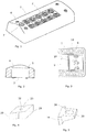
- a first example of a frame 1 according to the present invention is showed, which frame 1 is intended to be received in an opening of a wall, a roof, a floor or a bottom of a house, a ship, an electrical cabinet, a container etc.
- the wall, roof, floor or bottom could be expressed as any dividing structure or partition.
- the frame forms a transition for cables and/or pipes together with modules received in the frame 1.
- a number of modules 2 are received.
- the modules 2 are placed inside an opening 3 of the frame.
- the modules 2 are to receive pipes or cables.
- the modules 2 have a number of peelable sheets to adapt an inner diameter to the outer diameter of the received cable or pipe.
- an edge 5 is arranged at the upper end of the opening 3 receiving the modules 2, whereby the opening 3 transforms into a smaller opening 4 above the edge 5.
- the edge 5 goes all around the upper end of the opening.
- the frame 1 can be mounted to a partition by means of screws 6 or other suitable fastening means.
- a compression unit 8 forms an integrated part of the frame 1.
- the compression unit 8 is placed in a space at one end of the frame 1, which space is open downwards and towards the opening 3 of the frame 1.
- the upper part of the space is covered for retaining the compression unit in the space.
- the compression unit 8 comprises three main elements each having a wedge form. Of the three elements a lower compression wedge 9 and an upper compression wedge 10 have the same orientation, while a middle compression wedge 11 has a reverse orientation.
- the lower and upper compression wedges 9, 10 have one slanted surface each to be facing the middle compression wedge 11. The surface opposite the slanted surface of each lower and upper compression wedges 9, 10, respectively, is not slanted.
- the lower and upper compression wedges 9, 10 are almost identical. However, they may have different thickness, in order for the middle compression wedge 11 to be placed in a proper position in relation to the modules 2. Furthermore, one of the upper and lower compression wedges 9, 10 normally has a recess receiving a nut 37 co-operating with a compression screw 7. When placed in the compression unit 8 the slanted surface of the lower compression wedge 9 is facing upwards while the slanting surface of the upper compression wedge 10 is facing downwards. Seen in cross section a broad side 31 of the middle compression wedge 11 is facing the opening 3 of the frame 1, while broad sides 28 of the lower and upper compression wedges 9, 10 are facing a wall of the frame 1 opposite the opening 3 of the frame 1.
- the compression screw 7 is received in a circular opening 32 adapted to the size of the screw 7.
- the compression screw 7 is received inside a slot 34, giving the middle compression wedge 11 a possibility to slide in relation to the compression screw 7 and in relation to the lower and upper compression wedges 9, 10.
- a nut 37 is received at one end of the compression screw 7, which nut 37 is received in a recess of the lower compression wedge 9. The recess is formed after the nut 37 to assist in tightening of the compression screw 7 by hindering the nut 37 from rotating.
- the screws 6 for fixating the frame to a wall or the like are received in recesses 33 at opposite sides of the lower and upper compression wedges 9, 10.
- sleeves receiving the screws 6 are arranged in the frame, which sleeves form through openings for the screws 6.
- the sleeves are received in the recesses 33 of the lower and upper compression wedges 9, 10.
- the middle compression wedge 11 is less wide at the portion of the wedge including the slot 34 compared to the portion at the broad side 31.
- the portion having less width should be small enough to pass between the screws 6 used for fastening the frame 1.
- the middle compression wedge 11 is free to move in horizontal direction between the screws 6.
- the function of the compression unit 8 is indicted in Fig. 6 .
- the middle compression wedge 11 will be moved in the direction of the horizontal arrow of Fig. 6 when the lower and upper compression wedges 9, 10 are pressed towards each other.
- the middle compression wedge 11 is free to move in a horizontal direction thanks to the slot receiving the compression screw 7 and to the portion of the middle compression wedge 11 having a width that is smaller than the distance between the fixation means of the frame 1.
- the middle wedge 11 will move towards and compress the modules 2 inside the opening 3 of the frame 1.
- the lower and upper compression wedges 9, 10 are made of a plastic material, such as PA 66, 306F or similar, while the middle compression wedge 11 is made of a rubber material, such as EPDM, Roxylon or similar. Normally a lubricant is placed on the slanting contact surfaces of the compression wedges 9-11.
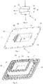
- Figs. 7-9 a further example of a frame 12 according to the present invention having an integrated compression unit is shown.
- the compression unit has the same general structure as for the compression unit 8 of the frame 1 of Figs. 1-4 and, thus, will not be described extensively here. However, in this case the compression unit has two compression screws 24.
- the frame 12 of Figs. 7-9 has an opening 13 for receiving a number of modules to receive cables or pipes.
- the compression unit is placed at one end of the opening 13 and a wall 14 projects above the compression unit.
- the frame 12 has a flange 15 projecting from an upper part of the frame 12 and encircling the opening 13.
- the opening 13 is formed by means of a wall 17, having the form of an open rectangle.
- the wall is formed of a framework 18.
- the wall 17 is perpendicular to the flange 15 and the modules are to be received in the opening 13 formed inside the wall 17.
- the wall 17 is normally placed inside an opening in a partition, such as a wall, and the flange 15 is fixed to the partition outside the opening of the wall.
- a number of apertures 16 are arranged at the periphery of the flange 15.
- the compression screws 24 may co-operate with nuts placed in recesses of the lower compression unit 25.
- the compression screws 24 go through circular openings in a lower compression wedge 25 and an upper compression wedge.
- the compression screws 24 are received in slots of a middle compression wedge 26.
- the fixation means for the frame 12 are not placed in connection with the compression unit.
- the compression wedges do not have to be adapted to receive any fixation means and may have a rectangular shape seen in plan view.
- the compression wedges have slanted surfaces resulting in that the middle compression wedge 26 will be pressed towards the centre of the opening 13 of the frame 12 when the compression screws 24 are tightened.
- ribs 35, 36 are arranged parallel with an edge between the wall 14 and the opening 13 of the frame 12.
- One rib 35 is arranged in connection with the openings for the compression screws 24.
- the other rib 36 is arranged at the end of the wall 14 and projects a short distance down into the opening 13. The part of the rib 36 projecting into the opening 13 will assist in retaining the compression unit 23 in the space below the wall 14.
- the ribs 35, 36 are arranged on the upper side of the wall 14, i.e. the opposite side of the compression unit 23.
- the frame 19 of Fig. 10 corresponds with the frame 12 of Figs. 7-9 except that the frame 19 of Fig. 10 has two openings each including an integrated compression unit 23.
- the frame 19 of Fig. 10 has a flange 20 and walls 21, which walls 21 encircle two openings.
- the frame 19 is shown with received modules 22. Between each row of modules a stay plate 27 is arranged.
- the modules 22 may have different sizes to receive cables or pipes of different diameters.
- the modules 22 are of a type having peelable sheets to adapt an inner diameter of the modules 22 to the outer diameter of the received cable or pipe.
- the middle compression wedge In use, irrespective of which of the above types of frame that is used, the middle compression wedge will be pressed towards the centre of the opening of the frame when the compression screw or screws are tightened, due to the slanted contact surfaces of the compression wedges. Thus, the middle compression wedge will press on the modules inside the opening, which modules are made of an elastic material and will be compressed. By the compression of the modules, the modules will be pressed against a cable or pipe received inside the opening of the frame.
- the design of the frames may vary.
- the type of frame shown in Figs. 1-4 has two openings receiving modules.
- the compression unit 8, 23 is normally manufactured together with the frame 1, 12, 19 in a joint process step. Also a seal may be manufactured in the joint process step, which seal is to seal against a partition in which the frame is received.
- the frame and integrated compression unit is normally formed by die-casting, but it is also possible to use injection moulding.
Landscapes
- Engineering & Computer Science (AREA)
- General Engineering & Computer Science (AREA)
- Architecture (AREA)
- Civil Engineering (AREA)
- Structural Engineering (AREA)
- Mechanical Engineering (AREA)
- Installation Of Indoor Wiring (AREA)
- Supports For Pipes And Cables (AREA)
- Laying Of Electric Cables Or Lines Outside (AREA)
- Patch Boards (AREA)
- Details Of Indoor Wiring (AREA)
Claims (8)
- Rahmen (1, 12, 9), der eine Öffnung (3, 3) zum Aufnehmen von einem oder mehr Modulen (2, 22) aufweist und zusammen mit den Modulen (2, 22) einen Übergang für Kabel oder Rohre bildet, wobei eine Kompressionseinheit (8, 23) ein integrierter Bestandteil des Rahmens (1, 12, 9) ist, diese Kompressionseinheit (8, 23) an einem Ende der Öffnung (3, 13) des Rahmens (1, 12, 9) in einem Raum unter einer Abdeckung angeordnet ist und dieser Raum zur Öffnung (3, 13) hin offen ist und wobei die Kompressionseinheit (8, 23) einen unteren Kompressionskeil (9, 25) und einen oberen Kompressionskeil (10) aufweist und wobei die Abdeckung über der Kompressionseinheit (8, 23) eine Wand (14) ist, diese Wand (14) eine oder mehr Öffnungen zum Aufnehmen von einer oder mehr Kompressionsschrauben (7, 24) hat,
dadurch gekennzeichnet, dass der Rahmen ferner einen mittleren Kompressionskeil (11, 26) aufweist, wobei die Kompressionskeile (9-11; 25, 26) geneigte gegenseitige Kontaktflächen haben, die Positionierung der Kompressionskeile (9-11, 25, 26) und ihrer geneigten gegenseitigen Kontaktflächen dergestalt ist, dass bei Beanspruchung auf Druck der untere und der obere Druckkeil (9, 25, 10) in einer Richtung aufeinander zu gepresst werden, so dass der mittlere Keil (11, 26) im Rahmen (1, 12, 9) zu den Modulen (2, 22) hin gepresst wird, und
wobei die Kompressionsschrauben (7, 24) durch jeden Kompressionskeil (9-11, 25, 26) hindurch verlaufen. - Rahmen nach Anspruch 1, wobei die eine oder mehr Kompressionsschrauben (7, 24) in einer kreisförmigen Öffnung (32) des unteren und des oberen Kompressionskeils (9, 10, 25) und in einer oder mehr Spalten (34) im mittleren Kompressionskeil (11, 26) aufgenommen sind.
- Rahmen nach Anspruch 1, wobei der untere und der obere Kompressionskeil (9, 10, 25) die gleiche Ausrichtung haben, während der mittlere Kompressionskeil (11, 26) eine umgekehrte Ausrichtung hat und wobei eine breite Seite (31) des mittleren Kompressionskeils (11, 26) der die Module (2, 22) aufnehmenden Öffnung (3, 13) des Rahmens (1, 12, 9) zugekehrt ist.
- Rahmen nach Anspruch 1, wobei der untere und der obere Kompressionskeil (9, 10, 25) an entgegengesetzten Seiten Aussparungen (33) haben, die Schäfte von Befestigungsmitteln für den Rahmen oder Aufnahmehülsen für die Befestigungsmittel aufnehmen, und wobei ein Teil des mittleren Kompressionskeils (11, 26), der von der Öffnung (3, 13) des Rahmens (1, 12, 19) weg gerichtet ist, eine Breite hat, die kleiner als der Abstand zwischen den Befestigungsmitteln oder den Aufnahmehülsen ist.
- Rahmen nach Anspruch 1, wobei ein Rand (5) an einem oberen Ende der die Module (2) aufnehmenden Öffnung (3) angeordnet ist, wobei diese Öffnung (3) über dem Rand (5) in eine kleinere Öffnung (4) übergeht, wobei diese Module (2) eine Abmessung haben, die sie daran hindert, am Rand (5) vorbeizukommen.
- Rahmen nach Anspruch 1, wobei die Wand (14) an der oberen Seite, d.h. der der Kompressionseinheit (23) entgegengesetzten Seite, eine oder mehr Rippen (35, 36) hat und wobei eine der Rippen (36) am freien Ende der Wand (14) positioniert ist und diese Rippe nach unten in die Öffnung (13) des Rahmens (12, 9) hineinragt.
- Rahmen nach Anspruch 1, wobei er einen Flansch (15, 20) hat, der die die Module (22) aufnehmende Öffnung (13) des Rahmens (15, 20) umgibt.
- Rahmen nach Anspruch 1, wobei der Rahmen (20) wenigstens zwei Module (22) aufnehmende Öffnungen hat und wobei an jeder Öffnung eine Kompressionseinheit (23) angeordnet ist.
Priority Applications (1)
| Application Number | Priority Date | Filing Date | Title |
|---|---|---|---|
| EP16163792.1A EP3057189A1 (de) | 2008-02-15 | 2009-01-21 | Rahmenübergang mit integrierter verdichtungseinheit |
Applications Claiming Priority (2)
| Application Number | Priority Date | Filing Date | Title |
|---|---|---|---|
| SE0800348A SE532027C2 (sv) | 2008-02-15 | 2008-02-15 | Genomföringsram med integrerad kompressionsenhet |
| PCT/SE2009/050059 WO2009102262A1 (en) | 2008-02-15 | 2009-01-21 | Transition frame with integrated compression unit |
Related Child Applications (2)
| Application Number | Title | Priority Date | Filing Date |
|---|---|---|---|
| EP16163792.1A Division EP3057189A1 (de) | 2008-02-15 | 2009-01-21 | Rahmenübergang mit integrierter verdichtungseinheit |
| EP16163792.1A Division-Into EP3057189A1 (de) | 2008-02-15 | 2009-01-21 | Rahmenübergang mit integrierter verdichtungseinheit |
Publications (3)
| Publication Number | Publication Date |
|---|---|
| EP2245713A1 EP2245713A1 (de) | 2010-11-03 |
| EP2245713A4 EP2245713A4 (de) | 2014-05-07 |
| EP2245713B1 true EP2245713B1 (de) | 2017-07-05 |
Family
ID=40957171
Family Applications (2)
| Application Number | Title | Priority Date | Filing Date |
|---|---|---|---|
| EP16163792.1A Ceased EP3057189A1 (de) | 2008-02-15 | 2009-01-21 | Rahmenübergang mit integrierter verdichtungseinheit |
| EP09710714.8A Active EP2245713B1 (de) | 2008-02-15 | 2009-01-21 | Übergangsrahmen mit integrierter kompressionseinheit |
Family Applications Before (1)
| Application Number | Title | Priority Date | Filing Date |
|---|---|---|---|
| EP16163792.1A Ceased EP3057189A1 (de) | 2008-02-15 | 2009-01-21 | Rahmenübergang mit integrierter verdichtungseinheit |
Country Status (11)
| Country | Link |
|---|---|
| US (1) | US8674240B2 (de) |
| EP (2) | EP3057189A1 (de) |
| JP (1) | JP5416141B2 (de) |
| KR (2) | KR101336496B1 (de) |
| BR (1) | BRPI0907936B1 (de) |
| CA (1) | CA2713986C (de) |
| DE (1) | DE202009019102U1 (de) |
| MX (1) | MX2010008413A (de) |
| SE (1) | SE532027C2 (de) |
| TW (1) | TW200936014A (de) |
| WO (1) | WO2009102262A1 (de) |
Families Citing this family (24)
| Publication number | Priority date | Publication date | Assignee | Title |
|---|---|---|---|---|
| EP1837573B1 (de) | 2006-03-20 | 2012-09-12 | Beele Engineering B.V. | Anordung zum dynamischen Abdichten einer Rohrhülse durch welches sich ein Rohr oder Kabel erstreckt |
| DE102010016722B4 (de) * | 2010-04-30 | 2011-12-08 | Rittal Gmbh & Co. Kg | Schaltschranksockel |
| EP2390544B1 (de) | 2010-05-25 | 2012-08-29 | Beele Engineering B.V. | Anordnung und Verfahren zur Bereitstellung eines Abdichtsystems in einer Öffnung |
| DE102010037463A1 (de) * | 2010-09-10 | 2012-03-15 | Phoenix Contact Gmbh & Co. Kg | Rahmen eines Kabeleinführungssystems und Kabeltülle hierfür |
| USD700895S1 (en) * | 2010-09-13 | 2014-03-11 | Phoenix Contact Gmbh & Co. Kg | Cable gland |
| ES2779424T5 (en) * | 2010-09-17 | 2025-04-21 | Roxtec Ab | Modular connector for cables or pipes and system comprising such modular connector |
| EP2792590B1 (de) * | 2011-12-16 | 2020-01-08 | Samsung Heavy Ind. Co., Ltd. | Struktur zur montage eines pumpenturms eines lng-speichertanks und herstellungsverfahren dafür |
| ES2626753T3 (es) | 2012-08-30 | 2017-07-25 | Beele Engineering B.V. | Sistema de estanqueidad para un espacio anular |
| NL2010304C2 (en) * | 2013-02-14 | 2014-08-18 | Beele Eng Bv | System for sealingly holding cables which extend through an opening. |
| EP3235357B1 (de) * | 2014-12-19 | 2023-06-07 | Hans-Erik Johansson I Hagstad Aktiebolag | Durchführung |
| SE539784C2 (en) * | 2015-05-04 | 2017-11-28 | Roxtec Ab | Indication means of a wedge of a lead-through system |
| DE202015102280U1 (de) * | 2015-05-05 | 2016-05-10 | Conta-Clip Verbindungstechnik Gmbh | Anordnung mit einer Wanddurchführung für mehrere Kabel und Bausatz |
| WO2017046064A1 (en) * | 2015-09-14 | 2017-03-23 | CommScope Connectivity Belgium BVBA | Sealing block arrangements for enclosures |
| DE202015106975U1 (de) * | 2015-12-21 | 2016-05-04 | Lapp Engineering & Co. | Kabeldurchführungsvorrichtung |
| DE202016103494U1 (de) * | 2016-06-30 | 2017-07-06 | Conta-Clip Verbindungstechnik Gmbh | Kabelwanddurchführung und Bausatz |
| CN106764094A (zh) * | 2016-11-18 | 2017-05-31 | 伊斯特密封科技(江苏)有限公司 | 一种模块式电缆、管道贯穿密封装置 |
| DE102016223425A1 (de) * | 2016-11-25 | 2018-05-30 | Icotek Project Gmbh & Co. Kg | Kabelhalter mit Trennwänden und einer Anzahl von Tüllen zum Hindurchführen von Kabeln |
| CN106848979A (zh) * | 2017-03-23 | 2017-06-13 | 江苏大洋海洋装备有限公司 | 带变径固定模块的电缆框 |
| USD849691S1 (en) * | 2017-04-18 | 2019-05-28 | Roxtec Ab | Frame for high density large cables |
| CN107196527B (zh) * | 2017-07-20 | 2023-04-18 | 常州博瑞电力自动化设备有限公司 | 用于光伏逆变器柜体的扣接式导流罩 |
| DE202017106818U1 (de) * | 2017-11-09 | 2018-11-14 | Conta-Clip Verbindungstechnik Gmbh | Anordnung für eine Kabeldurchführung |
| SE544601C2 (en) * | 2021-01-04 | 2022-09-20 | Roxtec Ab | A transit for passing cables and/or pipes through a partition opening and use of such a transit |
| US20220224097A1 (en) * | 2021-01-14 | 2022-07-14 | Quanta Computer Inc. | Cable-entry device for an electronic chassis |
| SE545653C2 (en) * | 2021-06-08 | 2023-11-28 | Roxtec Ab | A transit device for leading one or more cables and/or pipes through an opening in a partition |
Family Cites Families (18)
| Publication number | Priority date | Publication date | Assignee | Title |
|---|---|---|---|---|
| US2732226A (en) * | 1956-01-24 | Brattberg | ||
| US2674772A (en) * | 1951-09-19 | 1954-04-13 | Baldwin Lima Hamilton Corp | Clamp |
| US3282544A (en) | 1963-03-11 | 1966-11-01 | Lyckeaborgs Bruk Ab | Tight lead-through inlet frame device for electrical lines |
| SE414439B (sv) * | 1978-06-26 | 1980-07-28 | Eric Larsson | Anordning for gastett genomforande av ett antal kablar eller ror genom en oppning i en byggnadskonstruktion |
| SE441795B (sv) * | 1984-03-23 | 1985-11-04 | Lyckeaborgs Bruk Ab | Skyddsanordning for att dempa pulsformad hogfrekvent, elektromagnetisk stralnings passage genom en brandskyddande genomforing |
| GB2186441B (en) * | 1986-02-11 | 1990-01-10 | Hawke Cable Glands Ltd | Improved transit for cables and pipes |
| AT391044B (de) * | 1987-09-09 | 1990-08-10 | Doepfl Rudolf Gmbh | Einrichtung zur pressung von in einem rahmen befindlichen packstuecken zur herstellung von kabeldurchfuehrungen |
| DE8807280U1 (de) | 1988-06-03 | 1988-07-21 | Günther Klein Industriebedarf GmbH, 2070 Ahrensburg | Abschlußdichtung für Kabeldurchführungen |
| US5416271A (en) * | 1991-10-29 | 1995-05-16 | General Signal Corporation | Electrical cable penetration seal with compliant module |
| DE4340343C1 (de) | 1993-11-26 | 1995-03-02 | Nord Systemtechnik | Verfahren zur Herstellung von Kabeldurchführungen |
| SE503133C2 (sv) * | 1994-10-06 | 1996-04-01 | Roxtec Ab | Ledningsgenomföring |
| SE520363C2 (sv) * | 2001-12-14 | 2003-07-01 | Roxtec Int Ab | Genomföringsanordning för genomföring av långsträckt ledning genom en öppning i en vägg |
| SE519393C2 (sv) * | 2002-01-22 | 2003-02-25 | Roxtec Int Ab | Ram, för kabelgenomföring eller liknande, försedd med ett brytbart skydd |
| SE528099C2 (sv) * | 2004-01-30 | 2006-09-05 | Roxtec Ab | Kompressionsenhet för en ram som tar emot kompressibla enheter för rörgenomföring |
| SE528689C2 (sv) * | 2005-05-30 | 2007-01-23 | Roxtec Ab | Ram med avskärmning vid kabel- och/eller rörgenomföringar i en vägg eller annan skiljedel |
| DE102005062656B3 (de) * | 2005-12-21 | 2007-03-08 | Gk-System Gmbh | Vorrichtung zum Abdichten von eingesetzten Kabeln, Leitungen bzw. Rohren |
| SE0600367L (sv) * | 2006-02-17 | 2007-08-18 | Roxtec Ab | Kabelfasthållningsanordning |
| DE202006017469U1 (de) * | 2006-11-14 | 2007-02-15 | Roxtec Ab | Kompressionseinheit |
-
2008
- 2008-02-15 SE SE0800348A patent/SE532027C2/sv unknown
-
2009
- 2009-01-21 CA CA2713986A patent/CA2713986C/en active Active
- 2009-01-21 WO PCT/SE2009/050059 patent/WO2009102262A1/en not_active Ceased
- 2009-01-21 KR KR1020107019693A patent/KR101336496B1/ko active Active
- 2009-01-21 MX MX2010008413A patent/MX2010008413A/es active IP Right Grant
- 2009-01-21 JP JP2010546724A patent/JP5416141B2/ja active Active
- 2009-01-21 KR KR1020137022753A patent/KR20130103814A/ko not_active Withdrawn
- 2009-01-21 US US12/735,623 patent/US8674240B2/en active Active
- 2009-01-21 EP EP16163792.1A patent/EP3057189A1/de not_active Ceased
- 2009-01-21 DE DE202009019102.8U patent/DE202009019102U1/de not_active Expired - Lifetime
- 2009-01-21 BR BRPI0907936-0A patent/BRPI0907936B1/pt active IP Right Grant
- 2009-01-21 EP EP09710714.8A patent/EP2245713B1/de active Active
- 2009-02-02 TW TW098103140A patent/TW200936014A/zh unknown
Non-Patent Citations (1)
| Title |
|---|
| None * |
Also Published As
| Publication number | Publication date |
|---|---|
| BRPI0907936A2 (pt) | 2015-07-28 |
| CA2713986A1 (en) | 2009-01-21 |
| JP5416141B2 (ja) | 2014-02-12 |
| WO2009102262A1 (en) | 2009-08-20 |
| KR20100116652A (ko) | 2010-11-01 |
| KR101336496B1 (ko) | 2013-12-03 |
| EP3057189A1 (de) | 2016-08-17 |
| EP2245713A4 (de) | 2014-05-07 |
| US8674240B2 (en) | 2014-03-18 |
| KR20130103814A (ko) | 2013-09-24 |
| DE202009019102U1 (de) | 2016-06-24 |
| MX2010008413A (es) | 2010-11-26 |
| JP2011512780A (ja) | 2011-04-21 |
| US20100326724A1 (en) | 2010-12-30 |
| SE0800348L (sv) | 2009-08-16 |
| EP2245713A1 (de) | 2010-11-03 |
| SE532027C2 (sv) | 2009-10-06 |
| TW200936014A (en) | 2009-08-16 |
| BRPI0907936B1 (pt) | 2019-05-14 |
| CA2713986C (en) | 2014-09-09 |
Similar Documents
| Publication | Publication Date | Title |
|---|---|---|
| EP2245713B1 (de) | Übergangsrahmen mit integrierter kompressionseinheit | |
| EP2394085B1 (de) | Struktur aufgebaut aus einer vielzahl von rohr- oder kabeldurchführungsblöcken | |
| US8541699B2 (en) | Adjustable module | |
| EP1468217B1 (de) | Rahmen zum kabeleintritt oder dergleichen, der rahmen mit einem zerbrechbaren schutz | |
| US20050115733A1 (en) | Compression unit | |
| US8563877B2 (en) | Frame | |
| US8122655B2 (en) | Frame and method of comprising one or more elastic modules for cable entries, pipe penetrations or the like | |
| US11489324B2 (en) | Extension frame | |
| WO2025127983A1 (en) | A transit system for leading cables and pipes through a partition, use of an anchoring element for such a transit system and a method for providing the transit system | |
| WO2025063874A1 (en) | A stayplate for holding sealing modules in a transit system, use of a stayplate, transit system comprising such a stayplate and use thereof |
Legal Events
| Date | Code | Title | Description |
|---|---|---|---|
| PUAI | Public reference made under article 153(3) epc to a published international application that has entered the european phase |
Free format text: ORIGINAL CODE: 0009012 |
|
| 17P | Request for examination filed |
Effective date: 20100826 |
|
| AK | Designated contracting states |
Kind code of ref document: A1 Designated state(s): AT BE BG CH CY CZ DE DK EE ES FI FR GB GR HR HU IE IS IT LI LT LU LV MC MK MT NL NO PL PT RO SE SI SK TR |
|
| AX | Request for extension of the european patent |
Extension state: AL BA RS |
|
| DAX | Request for extension of the european patent (deleted) | ||
| A4 | Supplementary search report drawn up and despatched |
Effective date: 20140408 |
|
| RIC1 | Information provided on ipc code assigned before grant |
Ipc: F16L 5/08 20060101ALI20140402BHEP Ipc: H02G 3/22 20060101AFI20140402BHEP Ipc: F16L 5/14 20060101ALI20140402BHEP |
|
| 17Q | First examination report despatched |
Effective date: 20160818 |
|
| GRAP | Despatch of communication of intention to grant a patent |
Free format text: ORIGINAL CODE: EPIDOSNIGR1 |
|
| INTG | Intention to grant announced |
Effective date: 20170222 |
|
| GRAS | Grant fee paid |
Free format text: ORIGINAL CODE: EPIDOSNIGR3 |
|
| GRAA | (expected) grant |
Free format text: ORIGINAL CODE: 0009210 |
|
| AK | Designated contracting states |
Kind code of ref document: B1 Designated state(s): AT BE BG CH CY CZ DE DK EE ES FI FR GB GR HR HU IE IS IT LI LT LU LV MC MK MT NL NO PL PT RO SE SI SK TR |
|
| REG | Reference to a national code |
Ref country code: GB Ref legal event code: FG4D |
|
| REG | Reference to a national code |
Ref country code: CH Ref legal event code: EP |
|
| REG | Reference to a national code |
Ref country code: AT Ref legal event code: REF Ref document number: 907205 Country of ref document: AT Kind code of ref document: T Effective date: 20170715 |
|
| REG | Reference to a national code |
Ref country code: IE Ref legal event code: FG4D |
|
| REG | Reference to a national code |
Ref country code: DE Ref legal event code: R096 Ref document number: 602009046950 Country of ref document: DE |
|
| REG | Reference to a national code |
Ref country code: NL Ref legal event code: MP Effective date: 20170705 |
|
| REG | Reference to a national code |
Ref country code: AT Ref legal event code: MK05 Ref document number: 907205 Country of ref document: AT Kind code of ref document: T Effective date: 20170705 |
|
| REG | Reference to a national code |
Ref country code: LT Ref legal event code: MG4D Ref country code: NO Ref legal event code: T2 Effective date: 20170705 |
|
| PG25 | Lapsed in a contracting state [announced via postgrant information from national office to epo] |
Ref country code: HR Free format text: LAPSE BECAUSE OF FAILURE TO SUBMIT A TRANSLATION OF THE DESCRIPTION OR TO PAY THE FEE WITHIN THE PRESCRIBED TIME-LIMIT Effective date: 20170705 Ref country code: LT Free format text: LAPSE BECAUSE OF FAILURE TO SUBMIT A TRANSLATION OF THE DESCRIPTION OR TO PAY THE FEE WITHIN THE PRESCRIBED TIME-LIMIT Effective date: 20170705 Ref country code: NL Free format text: LAPSE BECAUSE OF FAILURE TO SUBMIT A TRANSLATION OF THE DESCRIPTION OR TO PAY THE FEE WITHIN THE PRESCRIBED TIME-LIMIT Effective date: 20170705 Ref country code: SE Free format text: LAPSE BECAUSE OF FAILURE TO SUBMIT A TRANSLATION OF THE DESCRIPTION OR TO PAY THE FEE WITHIN THE PRESCRIBED TIME-LIMIT Effective date: 20170705 Ref country code: AT Free format text: LAPSE BECAUSE OF FAILURE TO SUBMIT A TRANSLATION OF THE DESCRIPTION OR TO PAY THE FEE WITHIN THE PRESCRIBED TIME-LIMIT Effective date: 20170705 |
|
| PG25 | Lapsed in a contracting state [announced via postgrant information from national office to epo] |
Ref country code: IS Free format text: LAPSE BECAUSE OF FAILURE TO SUBMIT A TRANSLATION OF THE DESCRIPTION OR TO PAY THE FEE WITHIN THE PRESCRIBED TIME-LIMIT Effective date: 20171105 Ref country code: ES Free format text: LAPSE BECAUSE OF FAILURE TO SUBMIT A TRANSLATION OF THE DESCRIPTION OR TO PAY THE FEE WITHIN THE PRESCRIBED TIME-LIMIT Effective date: 20170705 Ref country code: BG Free format text: LAPSE BECAUSE OF FAILURE TO SUBMIT A TRANSLATION OF THE DESCRIPTION OR TO PAY THE FEE WITHIN THE PRESCRIBED TIME-LIMIT Effective date: 20171005 Ref country code: GR Free format text: LAPSE BECAUSE OF FAILURE TO SUBMIT A TRANSLATION OF THE DESCRIPTION OR TO PAY THE FEE WITHIN THE PRESCRIBED TIME-LIMIT Effective date: 20171006 Ref country code: PL Free format text: LAPSE BECAUSE OF FAILURE TO SUBMIT A TRANSLATION OF THE DESCRIPTION OR TO PAY THE FEE WITHIN THE PRESCRIBED TIME-LIMIT Effective date: 20170705 Ref country code: LV Free format text: LAPSE BECAUSE OF FAILURE TO SUBMIT A TRANSLATION OF THE DESCRIPTION OR TO PAY THE FEE WITHIN THE PRESCRIBED TIME-LIMIT Effective date: 20170705 |
|
| REG | Reference to a national code |
Ref country code: DE Ref legal event code: R097 Ref document number: 602009046950 Country of ref document: DE |
|
| PG25 | Lapsed in a contracting state [announced via postgrant information from national office to epo] |
Ref country code: DK Free format text: LAPSE BECAUSE OF FAILURE TO SUBMIT A TRANSLATION OF THE DESCRIPTION OR TO PAY THE FEE WITHIN THE PRESCRIBED TIME-LIMIT Effective date: 20170705 Ref country code: CZ Free format text: LAPSE BECAUSE OF FAILURE TO SUBMIT A TRANSLATION OF THE DESCRIPTION OR TO PAY THE FEE WITHIN THE PRESCRIBED TIME-LIMIT Effective date: 20170705 Ref country code: RO Free format text: LAPSE BECAUSE OF FAILURE TO SUBMIT A TRANSLATION OF THE DESCRIPTION OR TO PAY THE FEE WITHIN THE PRESCRIBED TIME-LIMIT Effective date: 20170705 |
|
| PLBE | No opposition filed within time limit |
Free format text: ORIGINAL CODE: 0009261 |
|
| STAA | Information on the status of an ep patent application or granted ep patent |
Free format text: STATUS: NO OPPOSITION FILED WITHIN TIME LIMIT |
|
| PG25 | Lapsed in a contracting state [announced via postgrant information from national office to epo] |
Ref country code: SK Free format text: LAPSE BECAUSE OF FAILURE TO SUBMIT A TRANSLATION OF THE DESCRIPTION OR TO PAY THE FEE WITHIN THE PRESCRIBED TIME-LIMIT Effective date: 20170705 Ref country code: EE Free format text: LAPSE BECAUSE OF FAILURE TO SUBMIT A TRANSLATION OF THE DESCRIPTION OR TO PAY THE FEE WITHIN THE PRESCRIBED TIME-LIMIT Effective date: 20170705 |
|
| 26N | No opposition filed |
Effective date: 20180406 |
|
| PG25 | Lapsed in a contracting state [announced via postgrant information from national office to epo] |
Ref country code: SI Free format text: LAPSE BECAUSE OF FAILURE TO SUBMIT A TRANSLATION OF THE DESCRIPTION OR TO PAY THE FEE WITHIN THE PRESCRIBED TIME-LIMIT Effective date: 20170705 |
|
| REG | Reference to a national code |
Ref country code: CH Ref legal event code: PL |
|
| GBPC | Gb: european patent ceased through non-payment of renewal fee |
Effective date: 20180121 |
|
| PG25 | Lapsed in a contracting state [announced via postgrant information from national office to epo] |
Ref country code: LU Free format text: LAPSE BECAUSE OF NON-PAYMENT OF DUE FEES Effective date: 20180121 Ref country code: FR Free format text: LAPSE BECAUSE OF NON-PAYMENT OF DUE FEES Effective date: 20180131 |
|
| REG | Reference to a national code |
Ref country code: IE Ref legal event code: MM4A |
|
| REG | Reference to a national code |
Ref country code: FR Ref legal event code: ST Effective date: 20180928 |
|
| REG | Reference to a national code |
Ref country code: BE Ref legal event code: MM Effective date: 20180131 |
|
| PG25 | Lapsed in a contracting state [announced via postgrant information from national office to epo] |
Ref country code: GB Free format text: LAPSE BECAUSE OF NON-PAYMENT OF DUE FEES Effective date: 20180121 Ref country code: BE Free format text: LAPSE BECAUSE OF NON-PAYMENT OF DUE FEES Effective date: 20180131 Ref country code: CH Free format text: LAPSE BECAUSE OF NON-PAYMENT OF DUE FEES Effective date: 20180131 Ref country code: LI Free format text: LAPSE BECAUSE OF NON-PAYMENT OF DUE FEES Effective date: 20180131 |
|
| PG25 | Lapsed in a contracting state [announced via postgrant information from national office to epo] |
Ref country code: IE Free format text: LAPSE BECAUSE OF NON-PAYMENT OF DUE FEES Effective date: 20180121 |
|
| PG25 | Lapsed in a contracting state [announced via postgrant information from national office to epo] |
Ref country code: IT Free format text: LAPSE BECAUSE OF NON-PAYMENT OF DUE FEES Effective date: 20180121 |
|
| PG25 | Lapsed in a contracting state [announced via postgrant information from national office to epo] |
Ref country code: IT Free format text: LAPSE BECAUSE OF NON-PAYMENT OF DUE FEES Effective date: 20180121 |
|
| PGRI | Patent reinstated in contracting state [announced from national office to epo] |
Ref country code: IT Effective date: 20190408 |
|
| PG25 | Lapsed in a contracting state [announced via postgrant information from national office to epo] |
Ref country code: MC Free format text: LAPSE BECAUSE OF FAILURE TO SUBMIT A TRANSLATION OF THE DESCRIPTION OR TO PAY THE FEE WITHIN THE PRESCRIBED TIME-LIMIT Effective date: 20170705 |
|
| PG25 | Lapsed in a contracting state [announced via postgrant information from national office to epo] |
Ref country code: MT Free format text: LAPSE BECAUSE OF NON-PAYMENT OF DUE FEES Effective date: 20180121 |
|
| PG25 | Lapsed in a contracting state [announced via postgrant information from national office to epo] |
Ref country code: TR Free format text: LAPSE BECAUSE OF FAILURE TO SUBMIT A TRANSLATION OF THE DESCRIPTION OR TO PAY THE FEE WITHIN THE PRESCRIBED TIME-LIMIT Effective date: 20170705 |
|
| PG25 | Lapsed in a contracting state [announced via postgrant information from national office to epo] |
Ref country code: HU Free format text: LAPSE BECAUSE OF FAILURE TO SUBMIT A TRANSLATION OF THE DESCRIPTION OR TO PAY THE FEE WITHIN THE PRESCRIBED TIME-LIMIT; INVALID AB INITIO Effective date: 20090121 Ref country code: PT Free format text: LAPSE BECAUSE OF FAILURE TO SUBMIT A TRANSLATION OF THE DESCRIPTION OR TO PAY THE FEE WITHIN THE PRESCRIBED TIME-LIMIT Effective date: 20170705 |
|
| PG25 | Lapsed in a contracting state [announced via postgrant information from national office to epo] |
Ref country code: MK Free format text: LAPSE BECAUSE OF NON-PAYMENT OF DUE FEES Effective date: 20170705 Ref country code: CY Free format text: LAPSE BECAUSE OF FAILURE TO SUBMIT A TRANSLATION OF THE DESCRIPTION OR TO PAY THE FEE WITHIN THE PRESCRIBED TIME-LIMIT Effective date: 20170705 |
|
| P01 | Opt-out of the competence of the unified patent court (upc) registered |
Effective date: 20230505 |
|
| PGFP | Annual fee paid to national office [announced via postgrant information from national office to epo] |
Ref country code: NO Payment date: 20260119 Year of fee payment: 18 Ref country code: DE Payment date: 20260120 Year of fee payment: 18 |
|
| PGFP | Annual fee paid to national office [announced via postgrant information from national office to epo] |
Ref country code: FI Payment date: 20260119 Year of fee payment: 18 Ref country code: IT Payment date: 20260119 Year of fee payment: 18 |