EP2245802B1 - Optimierte SIP-Routingarchitektur mit einem integrierten Netzwerk- und Systemansatz - Google Patents
Optimierte SIP-Routingarchitektur mit einem integrierten Netzwerk- und Systemansatz Download PDFInfo
- Publication number
- EP2245802B1 EP2245802B1 EP09707364.7A EP09707364A EP2245802B1 EP 2245802 B1 EP2245802 B1 EP 2245802B1 EP 09707364 A EP09707364 A EP 09707364A EP 2245802 B1 EP2245802 B1 EP 2245802B1
- Authority
- EP
- European Patent Office
- Prior art keywords
- sip
- sip signaling
- network
- session
- communication network
- Prior art date
- Legal status (The legal status is an assumption and is not a legal conclusion. Google has not performed a legal analysis and makes no representation as to the accuracy of the status listed.)
- Not-in-force
Links
Images









Classifications
-
- H—ELECTRICITY
- H04—ELECTRIC COMMUNICATION TECHNIQUE
- H04L—TRANSMISSION OF DIGITAL INFORMATION, e.g. TELEGRAPHIC COMMUNICATION
- H04L12/00—Data switching networks
- H04L12/02—Details
- H04L12/14—Charging, metering or billing arrangements specially adapted for data communications, e.g. authentication, authorisation and accounting [AAA] framework
-
- H—ELECTRICITY
- H04—ELECTRIC COMMUNICATION TECHNIQUE
- H04L—TRANSMISSION OF DIGITAL INFORMATION, e.g. TELEGRAPHIC COMMUNICATION
- H04L12/00—Data switching networks
- H04L12/02—Details
- H04L12/14—Charging, metering or billing arrangements specially adapted for data communications, e.g. authentication, authorisation and accounting [AAA] framework
- H04L12/1442—Charging, metering or billing arrangements specially adapted for data communications, e.g. authentication, authorisation and accounting [AAA] framework at network operator level
- H04L12/145—Charging, metering or billing arrangements specially adapted for data communications, e.g. authentication, authorisation and accounting [AAA] framework at network operator level trading network capacity or selecting route based on tariff
-
- H—ELECTRICITY
- H04—ELECTRIC COMMUNICATION TECHNIQUE
- H04L—TRANSMISSION OF DIGITAL INFORMATION, e.g. TELEGRAPHIC COMMUNICATION
- H04L41/00—Arrangements for maintenance, administration or management of data switching networks, e.g. of packet switching networks
- H04L41/50—Network service management, e.g. ensuring proper service fulfilment according to agreements
- H04L41/5003—Managing SLA; Interaction between SLA and QoS
- H04L41/5009—Determining service level performance parameters or violations of service level contracts, e.g. violations of agreed response time or mean time between failures [MTBF]
-
- H—ELECTRICITY
- H04—ELECTRIC COMMUNICATION TECHNIQUE
- H04L—TRANSMISSION OF DIGITAL INFORMATION, e.g. TELEGRAPHIC COMMUNICATION
- H04L41/00—Arrangements for maintenance, administration or management of data switching networks, e.g. of packet switching networks
- H04L41/50—Network service management, e.g. ensuring proper service fulfilment according to agreements
- H04L41/508—Network service management, e.g. ensuring proper service fulfilment according to agreements based on type of value added network service under agreement
- H04L41/5087—Network service management, e.g. ensuring proper service fulfilment according to agreements based on type of value added network service under agreement wherein the managed service relates to voice services
-
- H—ELECTRICITY
- H04—ELECTRIC COMMUNICATION TECHNIQUE
- H04L—TRANSMISSION OF DIGITAL INFORMATION, e.g. TELEGRAPHIC COMMUNICATION
- H04L45/00—Routing or path finding of packets in data switching networks
- H04L45/302—Route determination based on requested QoS
- H04L45/304—Route determination for signalling traffic
-
- H—ELECTRICITY
- H04—ELECTRIC COMMUNICATION TECHNIQUE
- H04L—TRANSMISSION OF DIGITAL INFORMATION, e.g. TELEGRAPHIC COMMUNICATION
- H04L45/00—Routing or path finding of packets in data switching networks
- H04L45/70—Routing based on monitoring results
-
- H—ELECTRICITY
- H04—ELECTRIC COMMUNICATION TECHNIQUE
- H04L—TRANSMISSION OF DIGITAL INFORMATION, e.g. TELEGRAPHIC COMMUNICATION
- H04L69/00—Network arrangements, protocols or services independent of the application payload and not provided for in the other groups of this subclass
- H04L69/40—Network arrangements, protocols or services independent of the application payload and not provided for in the other groups of this subclass for recovering from a failure of a protocol instance or entity, e.g. service redundancy protocols, protocol state redundancy or protocol service redirection
-
- H—ELECTRICITY
- H04—ELECTRIC COMMUNICATION TECHNIQUE
- H04L—TRANSMISSION OF DIGITAL INFORMATION, e.g. TELEGRAPHIC COMMUNICATION
- H04L43/00—Arrangements for monitoring or testing data switching networks
- H04L43/08—Monitoring or testing based on specific metrics, e.g. QoS, energy consumption or environmental parameters
- H04L43/0805—Monitoring or testing based on specific metrics, e.g. QoS, energy consumption or environmental parameters by checking availability
-
- H—ELECTRICITY
- H04—ELECTRIC COMMUNICATION TECHNIQUE
- H04L—TRANSMISSION OF DIGITAL INFORMATION, e.g. TELEGRAPHIC COMMUNICATION
- H04L43/00—Arrangements for monitoring or testing data switching networks
- H04L43/08—Monitoring or testing based on specific metrics, e.g. QoS, energy consumption or environmental parameters
- H04L43/0852—Delays
-
- H—ELECTRICITY
- H04—ELECTRIC COMMUNICATION TECHNIQUE
- H04L—TRANSMISSION OF DIGITAL INFORMATION, e.g. TELEGRAPHIC COMMUNICATION
- H04L45/00—Routing or path finding of packets in data switching networks
- H04L45/22—Alternate routing
-
- H—ELECTRICITY
- H04—ELECTRIC COMMUNICATION TECHNIQUE
- H04L—TRANSMISSION OF DIGITAL INFORMATION, e.g. TELEGRAPHIC COMMUNICATION
- H04L45/00—Routing or path finding of packets in data switching networks
- H04L45/28—Routing or path finding of packets in data switching networks using route fault recovery
-
- H—ELECTRICITY
- H04—ELECTRIC COMMUNICATION TECHNIQUE
- H04L—TRANSMISSION OF DIGITAL INFORMATION, e.g. TELEGRAPHIC COMMUNICATION
- H04L65/00—Network arrangements, protocols or services for supporting real-time applications in data packet communication
- H04L65/1066—Session management
- H04L65/1101—Session protocols
- H04L65/1104—Session initiation protocol [SIP]
-
- H—ELECTRICITY
- H04—ELECTRIC COMMUNICATION TECHNIQUE
- H04W—WIRELESS COMMUNICATION NETWORKS
- H04W40/00—Communication routing or communication path finding
- H04W40/34—Modification of an existing route
Definitions
- the present subject matter relates to communications networks supporting multimedia sessions over packet transport and more particularly to techniques and equipment to monitor parameters relating to communications with network components involved in session signaling and to dynamically route/reroute signaling traffic in an effective manner.
- SIP session initiation protocol
- SIP is an application-layer control protocol used to set-up, change and/or tear-down any of a variety of different types of multimedia sessions through a packet switched network.
- the actual multimedia communications typically utilize other application-layer protocols.
- Packets containing SIP signaling messages are transported through the packet switched network in essentially the same manner as other packets. However, because of the critical nature of such signaling messages, mechanisms have been developed to reroute or resend SIP signaling messages in the event of failures in communication of such messages.
- the relevant standard e.g. as set forth in Internet Engineering Taskforce (IETF), RFC 3261 SIP: Session Initiation Protocol, June 2002 , does not adequately address congestion, optimization, failure detection and recovery mechanisms for mission critical applications, such as wireless and/or wireline service providers, where SIP is a key protocol for many critical real time applications.
- Internet Engineering Taskforce (IETF), RFC Session Timers in the Session Initiation Protocol (SIP), April 2005 proposed an extension of the standard to determine if a SIP session is still active.
- the current technology for SIP rerouting relies on expiration of timers and associated retransmissions.
- the SIP client which can be executing as a process on a device in a mobile switching center for example, or a mobile device, reaches the remote SIP proxy, via various SIP servers, or back-to-back user agent (B2BUA) functions.
- B2BUA back-to-back user agent
- the current SIP specifications use retransmission timers, increased command sequence (Cseq) numbers, and Positive ACKs to detect a failed B2BUA, and initiate appropriate recovery action.
- the typical sequence of failure detection and recovery involves activation of a SIP retransmission timer, relative to the first B2BUA (B2BUA1) on the first UAC (UAC), when a new SIP request is received and a dialog is initiated with a second B2BUA (B2BUA2), for example a remote base station controller on a peering network.
- B2BUA1 B2BUA1
- B2BUA2 B2BUA2BUA2BUA2BUA2
- a particular SIP session is uniquely identified by the Call-ID and Cseq combination of values, hence this is the state information maintained by UAC1 and the remote peer UAS2. If a B2BUA involved in the session fails or if network connectivity with B2BUA1 fails, then the retransmit timer in UAC1 will time out.
- Expiration of the retransmit timer in UAC1 causes the UAC1 to initiate retransmission of the SIP message.
- the retransmission sequence includes an increase in the timer value, using a backoff exponential algorithm.
- the retransmission sequence typically will take on the order of seconds to tens of seconds, which is clearly unacceptable in a service provider network offering real time services, such as voice or video.
- This time window there is potential loss of call revenue if calls are not processed in a timely manner.
- Another problem, is that the backup SIP servers are statically configured, so the server is never sure it is the optimal SIP router to accept traffic with the given dynamic changes that occur in the network and servers.
- current technology reacts very slowly to changes in the control plan, such as failures or congestion (network or servers), which results in loss of revenue if calls are not processed in a timely manner.
- Document US 2005/0157707 A1 relates to a scalable, reliable session initiation protocol (SIP) signaling router which includes cluster nodes fore performing SIP services.
- a location server replicates its database of SIP location information to each of the cluster nodes. Because each cluster node maintains its own local copy of the SIP location database, the time for routing SIP signaling messages is decreased.
- SIP session initiation protocol
- Document US 2006/0176805 A1 relates to a method and apparatus for processing a contact with a client within a contact distributor.
- the method includes the steps of providing a primary SIP back-to-back user agent and an associated secondary SIP back-to-back user agent for each resource of a plurality of resources of the contact distributor and setting up a communication connection between the client and a resource through the primary back-to-back user agent of the resource.
- the present invention relates to a method as defined by independent claim 1, a session border controller as defined by independent claim 8 and a computer program product as defined by independent claim 9.
- the detailed examples discussed below provide a technology to optimize SIP traffic routing based on network and systems parameters, rather that on statically defined next hop SIP servers as in the current technology. Networking and system conditions change dynamically. To compensate for these dynamic fluctuations, a technique is provided to monitor key network and system parameters and dynamically adjust or tune SIP routing decisions. In particular the disclosed examples improve the selection of SIP Peering Servers by considering multiple measurements, that provide accurate information on the state of the network and systems to determine the optimal SIP routing plan.
- the SIP routing approach presented by way of example below further improves optimization by also considering other factors, such as transport costs, company policies, etc., to influence the SIP routing decisions.
- the exemplary solution disclosed in more detail below monitors the status and other conditions of key components in the signaling plan, such as network congestion and server delays.
- the SIP traffic can not only be diverted based on failures, but also be diverted based on best path optimization parameters.
- the cost of communications with various SIP signaling nodes may also be included as one of the parameters in the routing decisions.
- the network can automatically route SIP traffic quickly to optimal SIP servers. This will directly improve the reliability and performance of the SIP control plan and result in optimal allocation of network resources. Even in the event of a failure, the recovery is far more efficient as there is no need to delay until a timer expires.
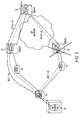
- the overall network 10 includes a number of networks operated by different entities.
- the various networks are operated by different network service provides or "carriers.”
- the network 10 utilizes packet transport and SIP signaling for session control purposes.
- the functional block diagram shows elements of the exemplary wireless mobile communication network 11, for providing packet based services, for multimedia applications such as mobile voice telephone services based on VoIP type packet communications, as well as video and/or other multimedia services.
- the drawing shows network elements in high-level functional block diagram form.
- the wireless communication network 11 provides packet communication services for numerous mobile stations, although for discussion purposes, the drawing shows a single device 13.
- the mobile device 13, for example, may take the form of a mobile telephone station, with display and user input capabilities to support multimedia communications.
- Today, such mobile telephones implementations of the device 13 typically take the form of portable handsets, although they may be implemented in other form factors.
- the mobile device 13 may take the form of a personal digital assistant (PDA) or a portable personal computer (PC), incorporating a wireless transceiver compatible with the particular type of wireless packet data service offered by the network 11.
- PDA personal digital assistant
- PC portable personal computer
- the mobile stations may take other forms or connect to a variety of other data devices that may enable use of the communication services of network 10.
- the network 11 includes or implements one or more radio access networks 15, for wireless communications with the mobile devices 13 receiving service via the network 11.
- Physical elements of a radio access network 15 include a number of base stations (BSs) 17, only one of which is shown for convenience.
- Each base station 17 includes an antenna system 19 and a base transceiver system (BTS) 21.
- the base transceiver system (BTS) 21 communicates via the antenna system 19 and the air-link with one or more of the mobile stations 13, when the mobile stations are within range.
- the BTS 21 is the part of the radio network that sends and receives radio frequency signals carrying packets to/from the mobile stations that the base station 17 currently serves.
- the BTS communications over the air link with the UA wireless client device 13 provide the High Rate Packet Data Interface (HPRD) for client data services. From the mobile station perspective, there will often be two or more base stations within range.
- the mobile device 13 communicates through the BTS 21 of base station 17, selected from among those base stations that it can detect (approximately within range) over the air, ending up with the BTS 21 that provides the best Channel-to-Interference ratio.
- the BTS 21 includes or is associated with a DOM (data optimized module) that controls the wireless packet communications through the BS and the HPRD wireless domain, including scheduling of packet transmissions on the forward link(s), in this example of the wireless portion of the network 11.
- the IP backhaul segment connects the BTS to the Radio Network Controller (RNC) 27, typically located in a Mobile Switching Center (MSC) 29.
- RNC Radio Network Controller
- MSC Mobile Switching Center
- This wireline segment may utilize Metro Ethernet connections provided by Regional Service providers to provide IP transport, as represented generally by routers 23, 25 and the links therebetween, for packet routing to and from the BTS 21 and the RNC 27 at the MSC 29.
- the network 11 also includes a number of Packet Data Serving Nodes or "PDSNs" in CDMA type networks (or GGSN deployed in GSM networks).
- PDSNs Packet Data Serving Nodes
- the MSC 29 serving the mobile device 13 the PDSN 31 serves as a foreign agent (FA).
- the PDSN is in packet communications with the RNC 27, e.g. via a local area network (LAN) within the MSC 29 represented generally by another router 33.
- the foreign agent PDSN 31 establishes, maintains and terminates logical links to the associated portion of the radio access network.
- the PDSN also supports point to point protocol (PPP) sessions with the mobile stations 13.
- PPP point to point protocol
- the PDSN provides the packet routing function from the radio network to/from other packet switched networks, in this case via the IP network 35 providing local area network (LAN) to wide area network (WAN) connectivity from the MSC 29 to a home agent (HA) PDSN 37, which in turn provides packet routing to/from an IP core network 39, e.g. for Internet or Intranet access.
- IP network 35 providing local area network (LAN) to wide area network (WAN) connectivity from the MSC 29 to a home agent (HA) PDSN 37, which in turn provides packet routing to/from an IP core network 39, e.g. for Internet or Intranet access.
- LAN local area network
- WAN wide area network
- HA home agent
- the agents 31 and 37 are coupled to an Authentication, Authorization, and Accounting (AAA) system 41.
- AAA Authentication, Authorization, and Accounting
- the PDSN FA 31 or the HA 37 accesses the AAA server 41 to obtain call access authorization, and the FA and HA provide information regarding the duration/volume of use during the session, to the AAA server for accounting purposes.
- the illustrated network 10 utilizes SIP as the signaling protocol for control of multimedia sessions or "calls" to and from the users' mobile stations 13 receiving service through the network.
- the core network 39 includes or provides secure communications with several elements utilized to implement relevant SIP signaling communications functions. SIP related elements, under discussion here, are shown; although other elements of the core network 39 such as routers, firewalls, etc. are omitted for convenience.
- the core network 39 implements one or more SIP servers 43, e.g. for SIP signaling to and from the UA functionality in the client mobile station devices 13.
- the exemplary core network 39 also implements a number of Session Border Controllers, as shown in this first example at 45 and 47.
- a Session Border Controller or "SBC” is a device used at a line of demarcation between networks to control at least the signaling and often the media communications, for multimedia communication sessions, such as voice over Internet Protocol (VoIP) calls.
- VoIP voice over Internet Protocol
- SBC devices are deployed at the boundary between an access network and a core network and/or between different core networks (e.g. at the interconnect between core networks of different carriers).
- the SBC 45 is one such device deployed at the boundary between the radio access network 15 and the core network 39
- the SBC 47 is one such device deployed at the boundary between the core network 39 and another IP network 49.
- a carrier grade network to provide adequate capacity and/or to provide redundancy and thereby insure a high degree of service availability, there will typically be a number of different servers 43 and there will usually be a number of SBCs 45, 47 implemented at each border or demarcation line.
- the other IP network 49 may be a public or private network.
- the IP network is that of another carrier or service provider.
- elements of the network 49 are generally omitted, it may be a wireless network implemented in a manner similar to the network 11 or any other type of IP network capable of multimedia session communications.
- the other network 49 will include one or more SBCs 51 configured as SIP peers with respect to the SBC 47 in the network 11.
- Sessions through the networks 11 and 49 allow communications for the mobile stations with other user agents (UAs), represented generally by the device shown at 53 in the first drawing.
- the other UA may be another end user device or a server or the like capable of multimedia communications, or the other device 53 may be a SIP server similar to the server 43.
- the SIP client can be executing as a process on a device in a mobile switching center 29 or on a mobile station 13. Handling of SIP signaling message traffic typically involves forwarding of the messages from at least one SIP device to another. Hence, any given SIP signaling message reaches the remote SIP proxy 43 or 53, via various SIP servers operating as back-to-back user agent (B2BUA) functions; and responses are forwarded back in a similar manner.
- B2BUA functions may reside on a server 43 in the core network 39, although in many cases, the B2BUA functions are implemented in the various SBCs.
- the network 10 dynamically implements routing decision for various SIP control signaling traffic based on detection of events and/or conditions that may result in suboptimal performance.
- one or more of the SIP signaling nodes monitors two or more parameters relating to communications of SIP signaling messages with other SIP signaling nodes.
- One of the SIP signaling nodes is identified as having optimal communications of SIP signaling messages, based on the monitoring of parameters and SIP signaling messages regarding one or more of the multimedia sessions are communicated with the identified SIP signaling node. This can include initiating signaling communication with another node, i.e. initial SIP routing.
- the technique can also be used for rerouting SIP control signaling traffic, for example, for rapid failure detection and recovery.
- Performance may relate to operational performance, such as availability status of communications with a particular node or congestion or latency impacting communications with a particular SIP signaling node. Performance also may relate to an aspect of commercial performance, e.g. cost of communications with a particular SIP signaling node.
- decisions for routing of SIP traffic signaling between devices such as 43, 45, 47 and 51 can be based on network and systems parameters, and routing decisions can be implemented dynamically as conditions of the SIP elements change.
- a technique is provided to monitor key network and system parameters and dynamically adjust or tune SIP routing/rerouting decisions.
- the disclosed examples improve the selection of SIP Peering Servers by considering multiple measurements, that provide accurate information on the state of the network and systems to determine the optimal SIP routing architecture.
- the SIP routing approach presented by way of example below further improves optimization by also considering other factors, such as transport costs, company policies, etc., to influence the SIP routing decisions.
- a back-to-back user agent is a logical entity that receives a request and processes it as a user agent server (UAS). In order to determine how the request should be answered, it acts as a user agent client (UAC) and generates requests. Unlike a proxy server, it maintains dialog state and must participate in all requests sent on the dialogs it has established.
- a transaction is a request sent by a client transaction function (using the transport layer) to a server transaction function, along with all responses to that request sent back from the server to the client.
- the transaction layer handles application-layer retransmissions, matching of responses to requests, and application-layer timeouts. Any task that a user agent client (UAC) accomplishes takes place using a series of transactions.
- UAC user agent client
- a dialog is a peer-to-peer SIP relationship between two user agents that persists for some time.
- a dialog established by SIP messages is identified by a call identifier, local tag, and a remote tag.
- a client is any network element that sends SIP requests and receives SIP responses. Clients may or may not interact directly with a human user.
- User agent clients and proxies are clients.
- a server is a network element that receives requests in order to service them and sends back responses to those requests. Examples of servers are proxies, user agent servers, redirect servers, and registrars.
- a proxy or proxy server is an intermediary entity that acts as both a server and a client for the purpose of making requests on behalf of other clients.
- a proxy server primarily plays the role of routing, which means its job is to ensure that a request is sent to another entity "closer" to the targeted user.
- Proxies are also useful for enforcing policy (for example, making sure a user is allowed to make a call).
- a proxy interprets, and, if necessary, rewrites specific parts of a request message before forwarding it.
- a User Agent is a logical entity that can act as both a user agent client and user agent server.
- a user agent client is a logical entity that creates and sends a new request to a server and receives any response to that request.
- a user agent server is a logical entity that generates a response to a SIP request, which may accept, reject or redirect the request.
- the role of UAC and UAS, as well as proxy and redirect servers, are defined on a transaction-by-transaction basis. For example, the user agent (UA) initiating a call acts as a UAC when it sends the initial INVITE request, but that same UA acts as a UAS when receiving a BYE request from the callee. Similarly, the same software can act as a proxy server for one request and as a redirect server for the next request.
- the SIP client 61 may be executing as a process on a device in a mobile switching center or a mobile device, and the client 61 communicates with a remote SIP proxy (not separately shown), via various SIP servers, or B2B2UA functions which are typically deployed on Session Border Controllers (SBCs).
- SBCs Session Border Controllers
- the end to end SIP primary path is shown as the dashed-doubled-dotted line. In the example, this primary path extends through routers R1 and R2 and two representative B2B2UA functions B2B2UA2 (63) and B2B2UA4 (65).
- the routers R1 and R2 could be any of the routers 23, 25 and 33 and/or one or more routers in the IP network 35 or the core network 39, in the example of FIG. 1 . If the remote SIP proxy is reached via another network, such as the network 49 in the example of FIG. 1 , then the B2B2UA2 function 63 might reside in an SBC 45 whereas the B2B2UA4 function 65 might reside in an SBC 47.
- the SIP elements monitor various parameters of the communications with other SIP signaling elements for purposes of making SIP route determinations on a dynamic basis.
- the SIP elements rely on a router protocol to periodically check or 'ping' the next hop element, such as the Bidirectional Forwarding Detection (BFD) protocol.
- BFD is a network protocol used to detect faults between two forwarding nodes. BFD establishes a session between two endpoints over a particular link. If more than one link exists between two systems, multiple BFD sessions may be established to monitor each one of them. Once, established, each node forwards BFD packets to the other, on a periodic basis.
- a node knows that there has been a failure, of the other forwarding node or of the network connectivity linking the nodes, if the packets stop arriving as expected.
- BFD was developed for routers, for purposes of making layer three determinations as to the status of other routers.
- the BFD functions are extended here to provide status information to the higher layers of the protocol stack associated with the SIP signaling communications.
- the forwarding nodes are back-to-back user agents (B2BUA), and the BFD functions are extended and used to detect faults between two B2BUA functions.
- the example of FIG. 2 therefore includes four exemplary BFD sessions, which are shown as dashed lines.
- the first BFD session BFD 1 - A2 is the BFD point to point, unidirectional session between router R1 and B2BUA2 (63).
- the second BFD session BFD 1 - A3 is the BFD point to point, unidirectional session between router R1 and B2BUA3 (67).
- the third BFD session, BFD A2 - A4 is the BFD point to point, unidirectional session between B2BUA2 (63) and B2BUA4 (65).
- the further BFD session BFD A3 - A4 is the BFD point to point, unidirectional session between B2BUA3 (67) and B2BUA4 (65). Similar BFD sessions are shown in FIG. 3 .
- the implementation includes extensions to the SIP specification where the SIP traffic can not only be diverted based on failures, but also be routed or diverted based on best path optimization parameters.
- the illustration in FIG. 2 assumes normal operations via the primary path through routers R1 and R2 and the B2B2UA functions B2B2UA2 (63) and B2B2UA4 (65), and the drawing shows the normal status monitoring through the four BFD sessions.
- the BFD sessions indicate that the links between the various B2BUA functions and the B2BUA functions themselves are operational.
- the timing of BFD responses may also be used to determine latencies with regard to the SIP message communications between the B2BUA functions.
- the status and/or latencies are used to make SIP routing decisions at the B2BUA functions. Other parameters, such as cost, may also be considered.
- FIG. 3 is useful in illustrating an event that may cause a dynamic decision to alter the SIP routing.
- a failure occurs on one of the SBC devices which implement the B2BUA functions, in this example, on the B2BUA2 (63).
- the B2BUA2 failure may occur due to, either a process, or a network connectivity issue connecting two endpoints between BFD1 and BFDA2.
- the following describes the sequence of actions when such a failure occurs.
- the router R1 knows that there is a failure between BFD1 and BFDA2, so it also knows that SIP packets destined to B2BUA2 (63) now is forwarded to B2BUA3 (67), using some pre-configurations done a priori.
- the function B2BUA3 (67) now will receive SIP packets, mid session. Since there is no state information associated with this SIP packet, it knows to send a 301 MOVED PERMANENTLY type SIP message to the SIP Client 61, which can be extracted from the SIP header field, or possibly also in some cases the source IP address. The SIP Client 61 therefore receives the SIP 301 MOVED PERMANENTLY message, with the Call-ID SIP header field and Cseq SIP header, identifying a unique transaction.
- the SIP Client 61 will re establish SIP connection with B2BUA3 (67), by issuing an new INVITE message, which the B2BUA3 (67) will use to rebuild new state information for this SIP session.
- the B2BUA4 function (65) will know that B2BUA2 (63) has failed due to BFD Session BFD A2 - A4 indicating the failure.
- the B2BUA4 function 65 now receives a new session establish message from B2BUA3 (67), which contains the same Cseq and other parameters, it knows that the identified SIP session has now moved. In this way, the communication between the SIP Client 61 and the B2BUA4 function 65 shifts from the primary route ( FIG. 2 ) to a secondary route shown as a dot-dash line through the B2BUA3 function 67.
- the backend corresponding session to the remote proxy server remains intact and decoupled from the effects of this failure.
- the SIP RE-INVITE message may be used as per RFC 3261, which states:
- the SIP Client 61 of UAC should be able to identify that the original dialog between the SIP Client and B2BUA2 (63) and the new dialog between the same SIP Client 61 and the new backup B2B2UA3 (67) should belong to the same session, so that the client will know that the RE-INVITE message is changing the target SIP server which should now be B2BUA3 (67).
- an implementation as outlined above includes extensions to the SIP specification where the SIP traffic can not only be diverted based on failures, but also be diverted based on best path optimization parameters.
- Other exemplary deployments are described below.
- FIG. 4 represents a logical network diagram that includes interconnect between two carriers' mobile networks, which includes SIP servers that process and route SIP traffic.
- This example shows communications between two mobile stations 71 and 73 receiving service from respective carrier networks (Ntwk 1) 72 and (Ntwk) 74.
- a mobile station 71 will originate a SIP session by first sending an INVITE message through the wireless network (e.g. network 11 of FIG. 1 ) to its configured SIP Proxy Server, SIP Proxy 1 (75), which is responsible for forwarding the INVITE to the target mobile station 73 via intermediate SIP Proxies, as shown in the diagram, from SIP Proxy 1 through SIP Proxy 2.
- SIP Proxy 1 intermediate SIP Proxies
- B2BUA1 (79) and B2BUA3 (81), are typically implemented in SBCs between the carriers networks 72 and 74.
- the carriers' networks will include other B2BUA2 (83) and B2BUA4 (85) functions, typically implemented in other SBCs between the carriers networks 72 and 74, although in our example, the normal session for the mobile stations 71 and 73 does not run through B2BUA2 (83) and B2BUA4 (85).
- the functions are described from a logical perspective, meaning the logical functions can be deployed on any physical box from a practical perspective.
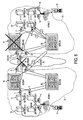
- FIG. 5 shows a decoupled architecture and SIP extensions for rapid SIP traffic diversion, and the drawing depicts an event where B2BUA3 (81) fails completely, and SIP traffic is appropriately rerouted.
- FIG. 6 is a similar diagram, which includes the steps for detecting the failure and rerouting the SIP signaling traffic around the failure, in an optimal manner.
- step 1 the B2BUA3 (81) fails, which interrupts the dialog 13 (step 2).
- the UAC1 in B2BUA1 (79) is notified instantaneously; and at step 3, that UAC1 takes corrective action and sets up an alternate session - in an optimal fashion, using a background process that dynamically maintains, updates an optimal routing table of SIP peers for UAC1.
- the UAC1 in B2BUA1 (79), using this extended information, will setup a dialog 14 (step 3) and start to forward SIP traffic to B2BUA4 (85).
- the SIP proxy 5 (87) may have had a session between SIP proxy 5 and UAC3 B2BUA3 (81), which needs to be torn down and a new one created between SIP Proxy 5 (87) and UAC3 in B2BUA4 (85).
- the SIP Proxy 5 (87) will be aware of the fact that UAC3 in B2BUA4 (85) is the next optimal SIP peer.
- SIP Proxy 5 (87) consults a dynamic SIP Routing Table to compute its next best optimal SIP peer, based on failures and other optimal criteria.
- step 4 a message (step 4) is sent to SIP Proxy 5 (87) to cause it to now divert SIP traffic to UAC3 in B2BUA4 (85), and to rapidly tear down the session leg from SIP Proxy 5 and UAS3 in the failed B2BUA3 (81).
- SIP Proxy 5 (87) has completed updating its tables, then SIP traffic will now flow from SIP Proxy 5 (87) to B2BUA4 (85) and then continue on to B2BUA1 (79).
- This decoupled architecture avoids the messy cascading or propagation of failure messages all the way to the head end, by containing the failure locally.
- the IP packets will have a different IP address, so the network will itself do simple IP packet forwarding based on route advertisements and installed in the routing tables.
- the adjacent SIP Proxy now routes to the backup B2BUA4 (85) instead of the failed B2BUA3 (81), which involves again simple IP routing of SIP traffic to a different IP destination address corresponding to B2BUA4 (85).
- the example for continuously and automatically finding the optimal SIP routing paths involves taking a measurement of parameters (e.g. status, congestion, latency, etc.) relating to health of all the SIP network links and servers, and based on the best paths, the SIP UAC and UAS will decide, in near real-time where and how to divert SIP traffic.
- parameters e.g. status, congestion, latency, etc.
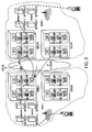
- FIG. 9 is a logical network diagram illustrating optimal SIP routing in accordance with an M/M/1 Queuing Model.
- the examples of finding the optimal SIP paths use the extension of the BFD process to continuously monitor status (available/unavailable) of communications, server backlog queues and the network latency and then let the BFD functionality decide the optimal SIP peers from the candidate of SIP peers that are already pre-configured as per original RFC 3261.
- the BFD1 function runs on a device such as a SBC that is acting as a B2BUA.
- a similar functionality BFD3 runs on another device such as a SBC that is acting as a B2BUA.
- BFD1 is continuously monitoring the network latency and the queues of Peer SIP servers UAS3 and UAS7 to determine Server Loads, as well as network latencies from current BFD protocol implementations. BFD1 will then provide the appropriate optimal SIP Peering information to UAC1 to create a dialog with the appropriate and optimal SIP Peer.
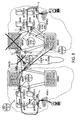
- FIGS. 7 and 8 show the basic packet flow for a mobile to mobile call, from one carrier to another.
- the following packet flows are defined:
- FIG. 8 also depicts the basic packet flow for a mobile to mobile call, from one carrier to another during a failure condition of either a Peering B2BUA link or a B2BUA device.
- the following new introduced packet flows are defined:
- the integration of the currently implemented BFD processes in existing routers that support this and the newly introduced BFD processes on the B2BUA devices should be 100% compatible.
- the new BFD processes on the B2BUA devices also may have added functionality as follows:
- the disclosed concepts are generic and intended to cover any specific implementation that takes any measurement to assist in determining the best SIP route, SIP peer etc.
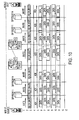
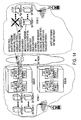
- FIGS. 10 and 11 illustrate Call Flow sequences in more detail regarding the SIP messages that will be triggered from Steady state, Sub-optimal Network and Systems Detection and Finally Recovery action.
- FIG. 10 shows the call setup, where there are N SIP proxies on the source and destination networks and there are B2BUA at the edge of each network.
- N SIP proxies on the source and destination networks and there are B2BUA at the edge of each network.
- the SIP Proxies do not need to maintain state, since there is enough information in the SIP message, such as the Via Header, to figure out the state associated with a call on an idempotent basis.
- FIG. 11 shows that there is a problem on one side of the network, for example the B2BUA3 box failing completely. Now the BFD process on each B2BUA will be able to make a reroute decision to route SIP traffic in an optimal fashion.
- the first event to take place would be that a new dialog is setup, initiated by B2BUA1, who has detected the failure of B2BUA3 with B2BUA4 and create a new dialog session.
- B2BUA4 Upon B2BUA4 realizing that it will take over traffic, that was originally going to B2BUA3, it will now notify SIP Proxy 5, to tell it that it will now forward SIP traffic originally going to B2BUA3, to B2BUA4.
- Another scenario, which can typically occur, is where one Service Provider has a deployed SBC controller, which contains an implementation of the B2BUA functions, peering with another provider who does not have an implementation of a B2BUA function but has a SIP Proxy.
- FIG. 12 shows a graphical example where one Service provider has a B2BUA function at its edge peering with another Service Provider, which only has a SIP Proxy.
- the B2BUA2 box has at least 1 BFD process that detects that B2BUA1 has failed and knows to notify the remote SIP Peering SIP Proxy 5, by sending a SIP Method, extension Method Failure as one way to notify to the SIP Proxy that B2BUA1 has failed (step 2 in the drawing). In this way, the SIP proxy 5 is instructed to now peer with B2BUA2.
- the remote SIP Proxy fails on the peering partner network (ntwk 2).
- the remote service provider will be responsible for finding an alternative, and can assume that a new SIP proxy will now forward traffic to the same B2BUA1.
- the SIP messages have enough state information, such as Cseq, Call ID, and Via messages, for the B2BUA1 box to figure out which message belongs to which session, regardless of this SIP Proxy the SIP message arrives from.
- a new SIP Method would be added to RFC 3261, to indicate that a new dialog is created to take over a failed or suboptimal B2BUA.
- the name of the SIP Proxy that needs to be notified of the SIP failure, which we can input into the INFO method.
- the proposed extension to the SIP methods would be something like FAILURE, which will tell the receiving SIP B2BUA that a failure has occurred and it is asked to check INFO parameters for more info on what needs to be done.
- Another possible alternative would be to include the SIP proxies to be notified in the Via messages of the FAILURE method only.
- the NOTIFY method can possibly also provide a simpler approach, with additional sub extensions to indicate optimization rerouting requests.
- SIP headers have a VIA field, which can tell the receiving B2BUA which signaling node to route the SIP request to.
- VIA field can tell the receiving B2BUA which signaling node to route the SIP request to.
- a second example might use Route Headers RFC 3261, 20.30, P.174.
- the record route header fields are inserted by proxies in a request to force future requests in the dialog to be routed through the same path.
- a third example might use Dialog - this is a logical SIP connection between 2 B2BUA, in particular between a UAC on B2BUA and a UAS on another.
- a dialog maintains necessary state for the routing and sequencing of messages between the UAC and UAS of different B2B2Uas.
- a dialog-ID (Call ID, local tag, remote tag) tracks individual sessions that are tunneled in a particular Dialog pipe.
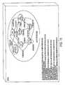
- FIG. 15 shows an example of a state machine for a UAS, which shows the typical states, in addition to an example of an additional state to implement the SIP Routing Optimization functionality.
- the additional state receives an asynchronous event from the BFD extended process to initiate a SIP Reroute action.
- the UAS is implemented in a stateful manner. It is well documented that the stateful implementation is far more powerful, with the ability to do retransmissions, billing etc. Stateless implementation can only look at limited information in the SIP message itself and attempt to deduce the current state of a message mid-flight and reroute accordingly, with many grey areas.
- FIG. 16 shows an example of a state machine for a UAC, which shows the typical states, in addition to an example of an additional state that implements the SIP Routing Optimization functionality.
- the additional state receives an asynchronous event from the BFD extended process to initiate a SIP Reroute action.
- the UAC also is implemented in a stateful manner, due to the fact that if there is a failure, the session states to do retransmits and other details for a particular session are required to maintain continuous operations.
- the functions relating to the monitoring and dynamic SIP routing may be implemented on computers connected for data communication via the components a packet data network 10.
- the relevant functions are performed in a server or the like operating as an SBC providing B2BUA capabilities, such as SBC 45 or 47 shown in FIG. 1 .
- Similar monitoring and dynamic routing may be implemented in SIP proxy servers, such as the server 43 in the example of FIG. 1 .
- SBC or proxy server such server devices for example, may be implemented using one or more hardware platforms intended to represent a general class of data processing device commonly used to run 'server' programming so as to implement the functions discussed above, albeit with an appropriate network connection for packet communication.
- FIGS. 17 and 18 provide functional block diagram illustrations of general purpose computer hardware platforms.
- FIG. 17 illustrates a network or host computer platform, as may typically be used to implement a server.
- FIG. 18 depicts a computer with user interface elements, as may be used to implement a personal computer or other type of work station, although the computer of FIG. 18 may also act as a server if appropriately programmed.
- the hardware elements, operating systems and programming languages of such servers are conventional in nature, and it is presumed that those skilled in the art are adequately familiar therewith.
- the server functions may be implemented in a distributed fashion on a number of similar platforms, to distribute the processing load.
- a computer operating as a server includes a data communication interface for packet data communication.
- the server computer also includes a central processing unit (“CPU"), in the form of one or more processors, for executing program instructions.
- the hardware also includes an internal communication bus as well as various types of memory or storage media (RAM, ROM, EEPROM, cache memory, disk drives, etc.) for code and data storage.
- the software functionalities involve programming, including executable code as well as associated stored data, e.g. SIP routing tables identifying peer signaling nodes.
- the software code is executable by the CPU or other processor of the general-purpose computer that functions as the server. In operation, the code is stored within the general-purpose computer platform.
- the software may be stored at other locations and/or transported for loading into the appropriate general-purpose computer system, e.g. via electrical communication media.
- Execution of programming by a processor of the computer platform enables the platform to implement the methodology for the monitoring and dynamic SIP routing, in essentially the manner performed in the implementations discussed and illustrated herein.
- terms such as computer or machine "readable medium” refer to any medium that participates in providing instructions to a processor for execution.
- aspects of the methods outlined above may be embodied in programming, e.g. in the form of software, firmware, or microcode executable by a server or other programmable device.
- Such programming typically is carried on or otherwise embodied in a medium or media, e.g. stored in a storage type medium.
- Terms such as “machine-readable” and “computer-readable” medium as used herein generically refer to any tangible medium that participates in providing instructions and/or data to a programmable processor, such as the CPU or other processor of a server computer or user terminal device, for execution or other processing.
- Such a medium may take many forms, including but not limited to, non-volatile storage media and volatile storage media.
- Non-volatile storage media include, for example, optical or magnetic disks and flash memory.
- Volatile storage media include dynamic memory, such as main memory or cache.
- machine-readable storage media include, for example, a floppy disk, a flexible disk, a hard disk, a magnetic tape, any other magnetic medium, a CD or CDROM, a DVD or DVD-ROM, any other optical medium, punch cards, paper tape, any other physical medium with patterns of holes, a RAM, a PROM, an EPROM, an EEPROM, a FLASH-EPROM, a cache memory, or any other memory chip or cartridge.
- AAA - Authentication, Authorization, and Accounting
- GSM Global System for Mobile communications
Landscapes
- Engineering & Computer Science (AREA)
- Computer Networks & Wireless Communication (AREA)
- Signal Processing (AREA)
- Business, Economics & Management (AREA)
- General Business, Economics & Management (AREA)
- Computer Security & Cryptography (AREA)
- Telephonic Communication Services (AREA)
- Data Exchanges In Wide-Area Networks (AREA)
- Mobile Radio Communication Systems (AREA)
Claims (9)
- Verfahren zum selektiven Routen von Signalisierungsnachrichten mit Bezug auf eine oder mehrere Multimediasitzungen für wenigstens einen Anwender durch ein Paketkommunikationsnetzwerk (11), wobei das Verfahren die Schritte umfasst:an einem ersten Sitzungsinitüerungsprotoll-SIP-Signalisierungsknoten, welcher dazu ausgelegt ist, eine Back-to-Back-Anwenderagentenfunktion B2BUA im Zusammenhang mit einem oder mehreren anderen SIP-Signalisierungsknoten bereitzustellen, erfolgendes Überwachen von wenigstens zwei Parametern mit Bezug auf Kommunikationen von SIP-Signalisierungsnachrichten der B2BUA-Funktion mit jedem des einen oder der mehreren anderen SIP-Signalisierungsknoten über das Paketkommunikationsnetzwerk, wobei jeder der anderen SIP-Signalisierungsknoten dazu ausgelegt ist, eine B2BUA-Funktion bereitzustellen;auf Grundlage des Überwachens der Parameter an dem ersten SIP-Signalisierungsknoten erfolgendes Identifizieren eines zweiten SIP-Signalisierungsknotens der anderen SIP-Signalisierungsknoten als denjenigen mit optimalen Kommunikationen von SIP-Signalisierungsnachrichten; undKommunizieren von SIP-Signalisierungsnachrichten mit Bezug auf eine oder mehrere der Multimediasitzungen zu oder von dem ersten SIP-Signalisierungsknoten mit dem identifizierten zweiten SIP-Signalisierungsknoten über das Paketkommunikationsnetzwerk (11).
- Verfahren nach Anspruch 1, wobei die wenigstens zwei Parameter mit Bezug auf eine Kommunikation der SIP-Signalisierungsnachrichten mit jedem der SIP-Signalisierungsknoten zwei oder mehr Parameter umfassen, welche an dem ersten SIP-Signalisierungsknoten überwacht werden, die dazu ausgestaltet sind eine B2BUA-Funktion bereitzustellen und aus einer Gruppe ausgewählt werden, die besteht aus:1) Verfügbarkeits-/Nichtverfügbarkeitsstatus einer Kommunikation mit jedem der SIP-Signalisierungsknoten;2) Überfüllung im Zusammenhang mit einer Kommunikation mit jedem der SIP-Signalisierungsknoten;3) Latenzrelevanter (latency impacting) Kommunikation mit jedem der SIP-Signalisierungsknoten; und4) Kosten bzw. Aufwand einer Kommunikation mit jedem der SIP-Signalisierungsknoten.
- Verfahren nach Anspruch 1, des Weiteren umfassend die nachfolgenden Schritte:Errichten einer jeweiligen Sitzung durch das Paketkommunikationsnetzwerk (11) mit jedem der SIP-Signalisierungsknoten; undperiodisches Austauschen von intaktheitsbezogenen Nachrichten mit jedem der SIP-Signalisierungsknoten über die jeweilige Sitzung durch das Paketkommunikationsnetzwerk (11);wobei der Überwachungsschritt wenigstens teilweise auf ein Überwachen von Paketen mit Empfang von intaktheitsbezogenen Nachrichten von jedem der SIP-Signalisierungsknoten über die jeweilige Sitzung durch das Paketkommunikati onsnetzwerk (11) anspricht.
- Verfahren nach Anspruch 3, wobei das Errichten der jeweiligen Sitzung mit jedem der SIP-Signalisierungsknoten und das Austauschen von intaktheitsbezogenen Nachrichten mit jedem der SIP-Signalisierungsknoten eine bidirektionale Weiterleitungserfassungs-BFD-Protokoll einsetzt.
- Verfahren nach Anspruch 1, wobei der erste SIP-Signalisierungsknoten eine Sitzungsgrenzsteuerung bzw. einen Sitzungsgrenzregler SBC umfasst.
- Verfahren nach Anspruch 1, wobei:das Paketkommunikationsnetzwerk (11) ein paketbasiertes mobiles Drahtloskommunikationsnetzwerk ist; undjede Multimediasitzung eine Sitzung zu oder von einer mobilen AnwenderagentenUA-Vorrichtung (31,37) umfasst.
- Verfahren nach Anspruch 6, wobei das mobile Drahtloskommunikationsnetzwerk (11) eine 3GPP2 1xEV-DO-Netzwerkarchitektur verwendet.
- Sitzungsgrenzsteuerung bzw. -regler, welches ausgelegt ist, als erster Sitzungsinitüerungsprotokoll-SIP-Signalisierungsknoten eine Back-to-Back-AnwenderagentenB2BUA-Funktion im Zusammenhang mit einer oder mehreren anderen SIP-Signalisierungsknoten zur SIP-Signalisierung über ein Paketkommunikationsnetzwerk (11) bereitzustellen, wobei die Sitzungsgrenzsteuerung bzw. der Sitzungsgrenzregler umfasst:eine Kommunikationsschnittstelle zur Verbindung mit dem Paketkommunikationsnetzwerk;eine zentrale Verarbeitungseinheit, die mit der Kommunikationsschnittstelle zum Signalisieren einer Kommunikation über das Paketkommunikationsnetzwerk (11) gekoppelt ist;einen Speicher, der mit der zentralen Verarbeitungseinheit gekoppelt ist; undeine Programmierung in dem Speicher zur Ausführung durch die zentrale Verarbeitungseinheit,wobei eine Ausführung der Programmierung durch die zentrale Verarbeitungseinheit bewirkt, dass die zentrale Verarbeitungseinheit die Sitzungsgrenzsteuerung bzw. den Sitzungsgrenzregler betätigt, um eine Abfolge von Schritten zum selektiven Routen von SIP-Signalisierungsnachrichten mit Bezug auf eine oder mehrere Multimediasitzungen für wenigstens einen Anwender durch das Paketkommunikationsnetzwerk zu implementieren, wobei die Abfolge von Schritten umfasst:a) Überwachen von wenigstens zwei Parametern mit Bezug auf Kommunikationen von SIP-Signalisierungsnachrichten mit jedem aus einer Mehrzahl der anderen SIP-Signalisierungsknoten über das Paketkommunikationsnetzwerk, wobei jeder der anderen SIP-Signalisierungsknoten zum Bereitstellen einer B2BUA-Funktion vorgesehen ist;b) auf Grundlage des Überwachens der Parameter erfolgendes Identifizieren eines zweiten SIP-Signalisierungsknotens der anderen SIP-Signalisierungsknoten als denjenigen mit optimalen Kommunikationen von SIP-Signalisierungsnachrichten; undc) Kommunizieren von SIP-Signalisierungsnachrichten im Zusammenhang mit einer oder mehreren der Multimediasitzungen zu oder von dem ersten SIP-Signalisierungsknoten mit dem identifizierten zweiten SIP-Signalisierungsknoten über das Paketkommunikationsnetzwerk (11).
- Computerprogrammerzeugnis, umfassend computerlesbare Anweisungen, die, wenn sie in ein Computersystem und/oder ein Computernetzwerksystem geladen sind und dort laufen, bewirken, dass das Computersystem und/oder das Computernetzwerksystem Vorgänge entsprechend einem Verfahren nach Anspruch 1 durchführen.
Applications Claiming Priority (2)
| Application Number | Priority Date | Filing Date | Title |
|---|---|---|---|
| US12/026,989 US7821923B2 (en) | 2008-02-06 | 2008-02-06 | Optimized SIP routing architecture using an integrated network and systems approach |
| PCT/US2009/033430 WO2009100359A1 (en) | 2008-02-06 | 2009-02-06 | Optimized sip routing architecture using an integrated network and systems approach |
Publications (3)
| Publication Number | Publication Date |
|---|---|
| EP2245802A1 EP2245802A1 (de) | 2010-11-03 |
| EP2245802A4 EP2245802A4 (de) | 2011-08-17 |
| EP2245802B1 true EP2245802B1 (de) | 2014-08-13 |
Family
ID=40931596
Family Applications (1)
| Application Number | Title | Priority Date | Filing Date |
|---|---|---|---|
| EP09707364.7A Not-in-force EP2245802B1 (de) | 2008-02-06 | 2009-02-06 | Optimierte SIP-Routingarchitektur mit einem integrierten Netzwerk- und Systemansatz |
Country Status (4)
| Country | Link |
|---|---|
| US (1) | US7821923B2 (de) |
| EP (1) | EP2245802B1 (de) |
| CA (1) | CA2715253A1 (de) |
| WO (1) | WO2009100359A1 (de) |
Families Citing this family (27)
| Publication number | Priority date | Publication date | Assignee | Title |
|---|---|---|---|---|
| FR2912271A1 (fr) * | 2007-02-06 | 2008-08-08 | France Telecom | Gestion de service dans un reseau |
| US8040796B2 (en) * | 2008-07-31 | 2011-10-18 | Alcatel Lucent | Voice over IP system recovery apparatus for service and packet groups based on failure detection thresholds |
| US20100042731A1 (en) * | 2008-08-01 | 2010-02-18 | Sparks Robert J | Methods, systems, and computer readable media for session initiation protocol (sip) dialog identification |
| JP5045603B2 (ja) * | 2008-08-07 | 2012-10-10 | 富士通株式会社 | 疎通監視方法、疎通監視システム、管理システム及び外部装置 |
| US20100185769A1 (en) * | 2009-01-16 | 2010-07-22 | Amlogic Co., Ltd. | Methods for Downloading a File to Consumer Electronic Devices via a Peer-to-peer Network |
| US8014292B1 (en) * | 2009-04-01 | 2011-09-06 | Sprint Communications Company L.P. | Dynamic location routing protocol |
| WO2010133237A1 (en) | 2009-05-19 | 2010-11-25 | Telefonaktiebolaget L M Ericsson (Publ) | Method and system for transfer of call control |
| EP2507970B1 (de) | 2009-12-04 | 2020-06-17 | Transpacific IP Group Limited | Verfahren zum senden und verarbeiten von sip-antworten |
| US8958282B2 (en) * | 2009-12-10 | 2015-02-17 | Verizon Patent And Licensing Inc. | 1-for-N redundancy in private IP session border control networks |
| DE102009060332B4 (de) * | 2009-12-23 | 2017-04-06 | Telefónica O2 Germany GmbH & Co. OHG | Verfahren und Vorrichtung zum Bereitstellen eines Telekommunikationsdienstes |
| CN101808022B (zh) * | 2010-04-22 | 2014-08-13 | 中兴通讯股份有限公司 | 双向转发检测的实现方法及装置 |
| US20120191872A1 (en) * | 2011-01-21 | 2012-07-26 | nex Vortex, Inc. | System and method for assuring service of sessions created by session initiation protocol (sip) in an internet protocol network |
| US8953501B2 (en) * | 2011-03-28 | 2015-02-10 | Avaya Inc. | IMS application sequencing optimizer |
| US9185170B1 (en) * | 2012-12-31 | 2015-11-10 | Juniper Networks, Inc. | Connectivity protocol delegation |
| US9948726B2 (en) * | 2013-07-01 | 2018-04-17 | Avaya Inc. | Reconstruction of states on controller failover |
| US10194008B2 (en) * | 2013-12-27 | 2019-01-29 | Nec Corporation | Communication device, network monitoring device system, and information notification method |
| CN106330586A (zh) * | 2015-06-29 | 2017-01-11 | 中兴通讯股份有限公司 | 一种提高交换网链路中业务检测可靠性的方法及装置 |
| US10469537B2 (en) * | 2015-10-01 | 2019-11-05 | Avaya Inc. | High availability take over for in-dialog communication sessions |
| WO2017081360A1 (en) * | 2015-11-10 | 2017-05-18 | Nokia Solutions And Networks Oy | Multi-connectivity of terminal device in cellular system |
| US10069871B2 (en) * | 2016-02-01 | 2018-09-04 | Verizon Patent And Licensing Inc. | Measuring session initiation protocol (SIP) messaging latency |
| US10432494B2 (en) * | 2017-01-18 | 2019-10-01 | Comcast Cable Communications, Llc | Optimizing network efficiency for application requirements |
| US10904073B2 (en) * | 2017-10-27 | 2021-01-26 | Hewlett Packard Enterprise Development Lp | Reassign standby user anchor controllers |
| US10469655B2 (en) * | 2018-03-21 | 2019-11-05 | Avaya Inc. | Call reconstruction sequenced application |
| US11349913B2 (en) | 2018-07-17 | 2022-05-31 | At&T Intellectual Property I, L.P. | Peer-to-peer network for telecommunication network traffic rerouting |
| US11108911B2 (en) * | 2018-07-17 | 2021-08-31 | Avaya Inc. | System and method for flexible routing |
| US12132767B2 (en) * | 2021-06-22 | 2024-10-29 | Dish Wireless L.L.C. | Systems and methods for performing automatic session control function change over |
| US20250379912A1 (en) * | 2024-06-07 | 2025-12-11 | T-Mobile Innovations Llc | Session binding control in wireless communication networks |
Family Cites Families (17)
| Publication number | Priority date | Publication date | Assignee | Title |
|---|---|---|---|---|
| US6157648A (en) * | 1997-03-06 | 2000-12-05 | Bell Atlantic Network Services, Inc. | Network session management |
| US7020707B2 (en) | 2001-05-30 | 2006-03-28 | Tekelec | Scalable, reliable session initiation protocol (SIP) signaling routing node |
| IL144141A0 (en) * | 2001-07-04 | 2002-05-23 | Method and system for improving a route along which data is sent using an ip protocol in a data communications network | |
| US9414255B2 (en) * | 2002-09-13 | 2016-08-09 | Alcatel Lucent | Packet flow control in a wireless communications network based on an indication contained in a packet |
| US7746797B2 (en) * | 2002-10-09 | 2010-06-29 | Nortel Networks Limited | Non-intrusive monitoring of quality levels for voice communications over a packet-based network |
| US7302053B2 (en) * | 2003-12-01 | 2007-11-27 | International Business Machines Corporation | System and method for providing a communication session |
| US7782787B2 (en) | 2004-06-18 | 2010-08-24 | Avaya Inc. | Rapid fault detection and recovery for internet protocol telephony |
| US7697480B2 (en) | 2004-11-22 | 2010-04-13 | Motorola, Inc | Method and apparatus for inter-system active handoff of a hybrid subscriber unit |
| US7688804B2 (en) * | 2005-02-08 | 2010-03-30 | Aspect Software, Inc. | Method of providing fault tolerance in a SIP based contact handling environment |
| US7489690B2 (en) | 2005-08-12 | 2009-02-10 | Cellco Partnership | Integrated packet latency aware QoS scheduling algorithm using proportional fairness and weighted fair queuing for wireless integrated multimedia packet services |
| US8300636B2 (en) | 2005-09-16 | 2012-10-30 | Acme Products, Inc. | Method and system of routing media packets in a network device |
| US7864710B2 (en) | 2005-12-20 | 2011-01-04 | Level 3 Communications, Llc | System and method for routing signaling messages in a communication network |
| US7765306B2 (en) | 2006-01-30 | 2010-07-27 | Cisco Technology, Inc. | Technique for enabling bidirectional forwarding detection between edge devices in a computer network |
| US8355413B2 (en) * | 2006-02-17 | 2013-01-15 | Cellco Partnership | Policy based procedure to modify or change granted QoS in real time for CDMA wireless networks |
| US8184549B2 (en) | 2006-06-30 | 2012-05-22 | Embarq Holdings Company, LLP | System and method for selecting network egress |
| US20080089324A1 (en) * | 2006-10-13 | 2008-04-17 | Cisco Technology, Inc | Indicating or remarking of a dscp for rtp of a flow (call) to and from a server |
| US8553692B2 (en) * | 2007-03-09 | 2013-10-08 | Cisco Technology, Inc. | Generic UDP multiplexing for voice over internet protocol (VOIP) |
-
2008
- 2008-02-06 US US12/026,989 patent/US7821923B2/en active Active
-
2009
- 2009-02-06 WO PCT/US2009/033430 patent/WO2009100359A1/en not_active Ceased
- 2009-02-06 EP EP09707364.7A patent/EP2245802B1/de not_active Not-in-force
- 2009-02-06 CA CA2715253A patent/CA2715253A1/en not_active Abandoned
Also Published As
| Publication number | Publication date |
|---|---|
| EP2245802A4 (de) | 2011-08-17 |
| US7821923B2 (en) | 2010-10-26 |
| US20090196183A1 (en) | 2009-08-06 |
| WO2009100359A1 (en) | 2009-08-13 |
| EP2245802A1 (de) | 2010-11-03 |
| CA2715253A1 (en) | 2009-08-13 |
Similar Documents
| Publication | Publication Date | Title |
|---|---|---|
| US7821923B2 (en) | Optimized SIP routing architecture using an integrated network and systems approach | |
| TWI528769B (zh) | 用於行動網際網路協定之虛擬轉交位址 | |
| US8547967B2 (en) | Method and apparatus for PSTN-based IP active call recovery and re-routing | |
| US20100223492A1 (en) | Node failure detection system and method for sip sessions in communication networks | |
| US20060187901A1 (en) | Concurrent dual-state proxy server, method of providing a proxy and SIP network employing the same | |
| US20080205277A1 (en) | Congestion control in an IP network | |
| US8964524B2 (en) | Method of routing an SIP message in the event of unavailability of intermediate nodes | |
| US20140029419A1 (en) | System, method and apparatus providing mvpn fast failover | |
| GB2397983A (en) | Session establishment in an ad-hoc mobile radio network | |
| US7706281B2 (en) | Selecting paths in multi-homed transport-layer network associations | |
| CN116762327B (zh) | 改进p-cscf服务器连接失败导致的ims注册失败的方法及系统 | |
| CN102714819A (zh) | 用于由服务集中和连续性应用服务器(scc as)发起的用户设备间转移(iut)、接入转移以及回退的方法和设备 | |
| JP2009296138A (ja) | 通信システム | |
| US20060165064A1 (en) | Method and apparatus for a network element to track the availability of other network elements | |
| US9369361B2 (en) | Method and apparatus for clearing hang calls | |
| EP1727309A1 (de) | Verfahren und Vorrichtung für die Überwachung der Verbindungsintegrität für die Verkehrssignalisierung über einen Pfad einer hybriden ATM/Ethernet Infrastruktur zur Unterstützung der Sprachpaketdienstbereitstellung | |
| US7751318B2 (en) | Method and system for computing AS-disjoint inter-AS traffic engineering-label switched paths (TE-LSPS) | |
| EP3295618B1 (de) | Routen in einem mehrwegnetz | |
| Cortes et al. | ISE03-3: Towards stateless core: Improving SIP proxy scalability | |
| CN102647397A (zh) | 一种sip会话保护的方法和系统 | |
| Jahanbakhsh et al. | Local and distributed SIP overload control solution improving sustainability of SIP networks | |
| WO2012116881A1 (en) | Methods, apparatuses, related computer program product for managing sessions | |
| Achour et al. | Inter-domain mobility management solution for service continuity in ims-based networks | |
| CN111492633A (zh) | 用于ims基础设施中的媒体传递会话的方法、系统和实体 | |
| Achour et al. | A SIP-SHIM6 based solution for seamless intra-domain mobility in IMS networks |
Legal Events
| Date | Code | Title | Description |
|---|---|---|---|
| PUAI | Public reference made under article 153(3) epc to a published international application that has entered the european phase |
Free format text: ORIGINAL CODE: 0009012 |
|
| 17P | Request for examination filed |
Effective date: 20100902 |
|
| AK | Designated contracting states |
Kind code of ref document: A1 Designated state(s): AT BE BG CH CY CZ DE DK EE ES FI FR GB GR HR HU IE IS IT LI LT LU LV MC MK MT NL NO PL PT RO SE SI SK TR |
|
| AX | Request for extension of the european patent |
Extension state: AL BA RS |
|
| DAX | Request for extension of the european patent (deleted) | ||
| A4 | Supplementary search report drawn up and despatched |
Effective date: 20110714 |
|
| RIC1 | Information provided on ipc code assigned before grant |
Ipc: H04L 12/26 20060101ALI20110708BHEP Ipc: H04L 12/56 20060101AFI20110708BHEP |
|
| 17Q | First examination report despatched |
Effective date: 20130108 |
|
| REG | Reference to a national code |
Ref country code: DE Ref legal event code: R079 Ref document number: 602009025931 Country of ref document: DE Free format text: PREVIOUS MAIN CLASS: H04L0012560000 Ipc: H04L0012260000 |
|
| GRAP | Despatch of communication of intention to grant a patent |
Free format text: ORIGINAL CODE: EPIDOSNIGR1 |
|
| RIC1 | Information provided on ipc code assigned before grant |
Ipc: H04L 12/707 20130101ALN20140220BHEP Ipc: H04L 12/725 20130101ALI20140220BHEP Ipc: H04L 29/06 20060101ALI20140220BHEP Ipc: H04L 12/24 20060101ALI20140220BHEP Ipc: H04L 12/26 20060101AFI20140220BHEP Ipc: H04W 40/34 20090101ALN20140220BHEP Ipc: H04L 12/703 20130101ALN20140220BHEP Ipc: H04L 12/721 20130101ALI20140220BHEP Ipc: H04L 29/14 20060101ALI20140220BHEP Ipc: H04L 12/14 20060101ALI20140220BHEP |
|
| INTG | Intention to grant announced |
Effective date: 20140312 |
|
| RIC1 | Information provided on ipc code assigned before grant |
Ipc: H04L 12/703 20130101ALN20140304BHEP Ipc: H04W 40/34 20090101ALN20140304BHEP Ipc: H04L 12/26 20060101AFI20140304BHEP Ipc: H04L 12/707 20130101ALN20140304BHEP Ipc: H04L 29/06 20060101ALI20140304BHEP Ipc: H04L 12/24 20060101ALI20140304BHEP Ipc: H04L 12/14 20060101ALI20140304BHEP Ipc: H04L 12/721 20130101ALI20140304BHEP Ipc: H04L 29/14 20060101ALI20140304BHEP Ipc: H04L 12/725 20130101ALI20140304BHEP |
|
| GRAS | Grant fee paid |
Free format text: ORIGINAL CODE: EPIDOSNIGR3 |
|
| GRAA | (expected) grant |
Free format text: ORIGINAL CODE: 0009210 |
|
| AK | Designated contracting states |
Kind code of ref document: B1 Designated state(s): AT BE BG CH CY CZ DE DK EE ES FI FR GB GR HR HU IE IS IT LI LT LU LV MC MK MT NL NO PL PT RO SE SI SK TR |
|
| REG | Reference to a national code |
Ref country code: GB Ref legal event code: FG4D |
|
| REG | Reference to a national code |
Ref country code: CH Ref legal event code: EP Ref country code: AT Ref legal event code: REF Ref document number: 682775 Country of ref document: AT Kind code of ref document: T Effective date: 20140815 |
|
| REG | Reference to a national code |
Ref country code: IE Ref legal event code: FG4D |
|
| REG | Reference to a national code |
Ref country code: DE Ref legal event code: R096 Ref document number: 602009025931 Country of ref document: DE Effective date: 20140925 |
|
| REG | Reference to a national code |
Ref country code: NL Ref legal event code: VDEP Effective date: 20140813 |
|
| REG | Reference to a national code |
Ref country code: AT Ref legal event code: MK05 Ref document number: 682775 Country of ref document: AT Kind code of ref document: T Effective date: 20140813 |
|
| REG | Reference to a national code |
Ref country code: LT Ref legal event code: MG4D |
|
| PG25 | Lapsed in a contracting state [announced via postgrant information from national office to epo] |
Ref country code: LT Free format text: LAPSE BECAUSE OF FAILURE TO SUBMIT A TRANSLATION OF THE DESCRIPTION OR TO PAY THE FEE WITHIN THE PRESCRIBED TIME-LIMIT Effective date: 20140813 Ref country code: GR Free format text: LAPSE BECAUSE OF FAILURE TO SUBMIT A TRANSLATION OF THE DESCRIPTION OR TO PAY THE FEE WITHIN THE PRESCRIBED TIME-LIMIT Effective date: 20141114 Ref country code: NO Free format text: LAPSE BECAUSE OF FAILURE TO SUBMIT A TRANSLATION OF THE DESCRIPTION OR TO PAY THE FEE WITHIN THE PRESCRIBED TIME-LIMIT Effective date: 20141113 Ref country code: BG Free format text: LAPSE BECAUSE OF FAILURE TO SUBMIT A TRANSLATION OF THE DESCRIPTION OR TO PAY THE FEE WITHIN THE PRESCRIBED TIME-LIMIT Effective date: 20141113 Ref country code: FI Free format text: LAPSE BECAUSE OF FAILURE TO SUBMIT A TRANSLATION OF THE DESCRIPTION OR TO PAY THE FEE WITHIN THE PRESCRIBED TIME-LIMIT Effective date: 20140813 Ref country code: PT Free format text: LAPSE BECAUSE OF FAILURE TO SUBMIT A TRANSLATION OF THE DESCRIPTION OR TO PAY THE FEE WITHIN THE PRESCRIBED TIME-LIMIT Effective date: 20141215 Ref country code: SE Free format text: LAPSE BECAUSE OF FAILURE TO SUBMIT A TRANSLATION OF THE DESCRIPTION OR TO PAY THE FEE WITHIN THE PRESCRIBED TIME-LIMIT Effective date: 20140813 Ref country code: ES Free format text: LAPSE BECAUSE OF FAILURE TO SUBMIT A TRANSLATION OF THE DESCRIPTION OR TO PAY THE FEE WITHIN THE PRESCRIBED TIME-LIMIT Effective date: 20140813 |
|
| PG25 | Lapsed in a contracting state [announced via postgrant information from national office to epo] |
Ref country code: CY Free format text: LAPSE BECAUSE OF FAILURE TO SUBMIT A TRANSLATION OF THE DESCRIPTION OR TO PAY THE FEE WITHIN THE PRESCRIBED TIME-LIMIT Effective date: 20140813 Ref country code: HR Free format text: LAPSE BECAUSE OF FAILURE TO SUBMIT A TRANSLATION OF THE DESCRIPTION OR TO PAY THE FEE WITHIN THE PRESCRIBED TIME-LIMIT Effective date: 20140813 Ref country code: IS Free format text: LAPSE BECAUSE OF FAILURE TO SUBMIT A TRANSLATION OF THE DESCRIPTION OR TO PAY THE FEE WITHIN THE PRESCRIBED TIME-LIMIT Effective date: 20141213 Ref country code: LV Free format text: LAPSE BECAUSE OF FAILURE TO SUBMIT A TRANSLATION OF THE DESCRIPTION OR TO PAY THE FEE WITHIN THE PRESCRIBED TIME-LIMIT Effective date: 20140813 Ref country code: AT Free format text: LAPSE BECAUSE OF FAILURE TO SUBMIT A TRANSLATION OF THE DESCRIPTION OR TO PAY THE FEE WITHIN THE PRESCRIBED TIME-LIMIT Effective date: 20140813 |
|
| PG25 | Lapsed in a contracting state [announced via postgrant information from national office to epo] |
Ref country code: NL Free format text: LAPSE BECAUSE OF FAILURE TO SUBMIT A TRANSLATION OF THE DESCRIPTION OR TO PAY THE FEE WITHIN THE PRESCRIBED TIME-LIMIT Effective date: 20140813 |
|
| PG25 | Lapsed in a contracting state [announced via postgrant information from national office to epo] |
Ref country code: EE Free format text: LAPSE BECAUSE OF FAILURE TO SUBMIT A TRANSLATION OF THE DESCRIPTION OR TO PAY THE FEE WITHIN THE PRESCRIBED TIME-LIMIT Effective date: 20140813 Ref country code: DK Free format text: LAPSE BECAUSE OF FAILURE TO SUBMIT A TRANSLATION OF THE DESCRIPTION OR TO PAY THE FEE WITHIN THE PRESCRIBED TIME-LIMIT Effective date: 20140813 Ref country code: IT Free format text: LAPSE BECAUSE OF FAILURE TO SUBMIT A TRANSLATION OF THE DESCRIPTION OR TO PAY THE FEE WITHIN THE PRESCRIBED TIME-LIMIT Effective date: 20140813 Ref country code: SK Free format text: LAPSE BECAUSE OF FAILURE TO SUBMIT A TRANSLATION OF THE DESCRIPTION OR TO PAY THE FEE WITHIN THE PRESCRIBED TIME-LIMIT Effective date: 20140813 Ref country code: CZ Free format text: LAPSE BECAUSE OF FAILURE TO SUBMIT A TRANSLATION OF THE DESCRIPTION OR TO PAY THE FEE WITHIN THE PRESCRIBED TIME-LIMIT Effective date: 20140813 Ref country code: RO Free format text: LAPSE BECAUSE OF FAILURE TO SUBMIT A TRANSLATION OF THE DESCRIPTION OR TO PAY THE FEE WITHIN THE PRESCRIBED TIME-LIMIT Effective date: 20140813 |
|
| REG | Reference to a national code |
Ref country code: DE Ref legal event code: R097 Ref document number: 602009025931 Country of ref document: DE |
|
| PG25 | Lapsed in a contracting state [announced via postgrant information from national office to epo] |
Ref country code: PL Free format text: LAPSE BECAUSE OF FAILURE TO SUBMIT A TRANSLATION OF THE DESCRIPTION OR TO PAY THE FEE WITHIN THE PRESCRIBED TIME-LIMIT Effective date: 20140813 |
|
| PLBE | No opposition filed within time limit |
Free format text: ORIGINAL CODE: 0009261 |
|
| STAA | Information on the status of an ep patent application or granted ep patent |
Free format text: STATUS: NO OPPOSITION FILED WITHIN TIME LIMIT |
|
| PG25 | Lapsed in a contracting state [announced via postgrant information from national office to epo] |
Ref country code: BE Free format text: LAPSE BECAUSE OF NON-PAYMENT OF DUE FEES Effective date: 20150228 |
|
| 26N | No opposition filed |
Effective date: 20150515 |
|
| REG | Reference to a national code |
Ref country code: DE Ref legal event code: R119 Ref document number: 602009025931 Country of ref document: DE |
|
| PG25 | Lapsed in a contracting state [announced via postgrant information from national office to epo] |
Ref country code: LU Free format text: LAPSE BECAUSE OF FAILURE TO SUBMIT A TRANSLATION OF THE DESCRIPTION OR TO PAY THE FEE WITHIN THE PRESCRIBED TIME-LIMIT Effective date: 20150206 |
|
| REG | Reference to a national code |
Ref country code: CH Ref legal event code: PL |
|
| GBPC | Gb: european patent ceased through non-payment of renewal fee |
Effective date: 20150206 |
|
| PG25 | Lapsed in a contracting state [announced via postgrant information from national office to epo] |
Ref country code: CH Free format text: LAPSE BECAUSE OF NON-PAYMENT OF DUE FEES Effective date: 20150228 Ref country code: LI Free format text: LAPSE BECAUSE OF NON-PAYMENT OF DUE FEES Effective date: 20150228 Ref country code: MC Free format text: LAPSE BECAUSE OF FAILURE TO SUBMIT A TRANSLATION OF THE DESCRIPTION OR TO PAY THE FEE WITHIN THE PRESCRIBED TIME-LIMIT Effective date: 20140813 |
|
| REG | Reference to a national code |
Ref country code: IE Ref legal event code: MM4A |
|
| REG | Reference to a national code |
Ref country code: FR Ref legal event code: ST Effective date: 20151030 |
|
| PG25 | Lapsed in a contracting state [announced via postgrant information from national office to epo] |
Ref country code: SI Free format text: LAPSE BECAUSE OF FAILURE TO SUBMIT A TRANSLATION OF THE DESCRIPTION OR TO PAY THE FEE WITHIN THE PRESCRIBED TIME-LIMIT Effective date: 20140813 |
|
| PG25 | Lapsed in a contracting state [announced via postgrant information from national office to epo] |
Ref country code: IE Free format text: LAPSE BECAUSE OF NON-PAYMENT OF DUE FEES Effective date: 20150206 Ref country code: GB Free format text: LAPSE BECAUSE OF NON-PAYMENT OF DUE FEES Effective date: 20150206 Ref country code: DE Free format text: LAPSE BECAUSE OF NON-PAYMENT OF DUE FEES Effective date: 20150901 |
|
| PG25 | Lapsed in a contracting state [announced via postgrant information from national office to epo] |
Ref country code: FR Free format text: LAPSE BECAUSE OF NON-PAYMENT OF DUE FEES Effective date: 20150302 |
|
| PG25 | Lapsed in a contracting state [announced via postgrant information from national office to epo] |
Ref country code: BE Free format text: LAPSE BECAUSE OF FAILURE TO SUBMIT A TRANSLATION OF THE DESCRIPTION OR TO PAY THE FEE WITHIN THE PRESCRIBED TIME-LIMIT Effective date: 20140813 |
|
| PG25 | Lapsed in a contracting state [announced via postgrant information from national office to epo] |
Ref country code: MT Free format text: LAPSE BECAUSE OF FAILURE TO SUBMIT A TRANSLATION OF THE DESCRIPTION OR TO PAY THE FEE WITHIN THE PRESCRIBED TIME-LIMIT Effective date: 20140813 |
|
| PG25 | Lapsed in a contracting state [announced via postgrant information from national office to epo] |
Ref country code: HU Free format text: LAPSE BECAUSE OF FAILURE TO SUBMIT A TRANSLATION OF THE DESCRIPTION OR TO PAY THE FEE WITHIN THE PRESCRIBED TIME-LIMIT; INVALID AB INITIO Effective date: 20090206 |
|
| PG25 | Lapsed in a contracting state [announced via postgrant information from national office to epo] |
Ref country code: TR Free format text: LAPSE BECAUSE OF FAILURE TO SUBMIT A TRANSLATION OF THE DESCRIPTION OR TO PAY THE FEE WITHIN THE PRESCRIBED TIME-LIMIT Effective date: 20140813 |
|
| PG25 | Lapsed in a contracting state [announced via postgrant information from national office to epo] |
Ref country code: MK Free format text: LAPSE BECAUSE OF FAILURE TO SUBMIT A TRANSLATION OF THE DESCRIPTION OR TO PAY THE FEE WITHIN THE PRESCRIBED TIME-LIMIT Effective date: 20140813 |