EP2245840B1 - Anzeigen von anruferinformationen auf einer mit einem drahtlosen lokalen netzwerk verbundenen einrichtung - Google Patents
Anzeigen von anruferinformationen auf einer mit einem drahtlosen lokalen netzwerk verbundenen einrichtung Download PDFInfo
- Publication number
- EP2245840B1 EP2245840B1 EP08712817.9A EP08712817A EP2245840B1 EP 2245840 B1 EP2245840 B1 EP 2245840B1 EP 08712817 A EP08712817 A EP 08712817A EP 2245840 B1 EP2245840 B1 EP 2245840B1
- Authority
- EP
- European Patent Office
- Prior art keywords
- message
- user equipment
- local network
- wireless local
- displaying device
- Prior art date
- Legal status (The legal status is an assumption and is not a legal conclusion. Google has not performed a legal analysis and makes no representation as to the accuracy of the status listed.)
- Not-in-force
Links
- 238000004891 communication Methods 0.000 claims description 28
- 238000000034 method Methods 0.000 claims description 27
- 238000004590 computer program Methods 0.000 claims description 18
- 238000012546 transfer Methods 0.000 claims description 5
- 238000012545 processing Methods 0.000 claims description 4
- 238000010295 mobile communication Methods 0.000 description 4
- 230000008569 process Effects 0.000 description 4
- 238000005516 engineering process Methods 0.000 description 3
- 230000006870 function Effects 0.000 description 3
- 101000826116 Homo sapiens Single-stranded DNA-binding protein 3 Proteins 0.000 description 1
- 102100023008 Single-stranded DNA-binding protein 3 Human genes 0.000 description 1
- HVYLDJKDVOOTHV-UHFFFAOYSA-N acetic acid;2-iminoethanethiol Chemical compound CC(O)=O.CC(O)=O.SCC=N HVYLDJKDVOOTHV-UHFFFAOYSA-N 0.000 description 1
- 230000003213 activating effect Effects 0.000 description 1
- 230000004913 activation Effects 0.000 description 1
- 230000006978 adaptation Effects 0.000 description 1
- 230000003044 adaptive effect Effects 0.000 description 1
- 230000005540 biological transmission Effects 0.000 description 1
- 238000010276 construction Methods 0.000 description 1
- 238000013500 data storage Methods 0.000 description 1
- 238000013461 design Methods 0.000 description 1
- 230000000694 effects Effects 0.000 description 1
- 230000000977 initiatory effect Effects 0.000 description 1
- 238000012986 modification Methods 0.000 description 1
- 230000004048 modification Effects 0.000 description 1
- 230000006855 networking Effects 0.000 description 1
- 230000004044 response Effects 0.000 description 1
- 230000011664 signaling Effects 0.000 description 1
- 230000009466 transformation Effects 0.000 description 1
Images

Classifications
-
- H—ELECTRICITY
- H04—ELECTRIC COMMUNICATION TECHNIQUE
- H04M—TELEPHONIC COMMUNICATION
- H04M1/00—Substation equipment, e.g. for use by subscribers
- H04M1/57—Arrangements for indicating or recording the number of the calling subscriber at the called subscriber's set
-
- H—ELECTRICITY
- H04—ELECTRIC COMMUNICATION TECHNIQUE
- H04M—TELEPHONIC COMMUNICATION
- H04M1/00—Substation equipment, e.g. for use by subscribers
- H04M1/72—Mobile telephones; Cordless telephones, i.e. devices for establishing wireless links to base stations without route selection
- H04M1/724—User interfaces specially adapted for cordless or mobile telephones
- H04M1/72403—User interfaces specially adapted for cordless or mobile telephones with means for local support of applications that increase the functionality
- H04M1/72409—User interfaces specially adapted for cordless or mobile telephones with means for local support of applications that increase the functionality by interfacing with external accessories
- H04M1/72412—User interfaces specially adapted for cordless or mobile telephones with means for local support of applications that increase the functionality by interfacing with external accessories using two-way short-range wireless interfaces
Definitions
- the present invention relates to a method, a user equipment, a computer program and a computer program product for enabling caller information to be displayed on a displaying device.
- Caller ID (Caller Identification) or CNID (calling number identification) is a telephone service that transmits the caller's number to the called party's telephone equipment before the call is answered. Where available, caller ID can also provide a name associated with the calling telephone number. Consumers can today also buy equipment or subscribe to enhanced Caller ID services that show the caller ID on a TV (Television) screen at home when a telephone connected to a PSTN (Public Switched Telephone Network) receives a call provided that a Caller ID service is enabled by a local phone company.
- PSTN Public Switched Telephone Network
- IMS IP Multimedia Subsystem
- 3GPP 3 rd Generation Partnership Project
- IMS network can be deployed to initiate and control multimedia sessions for IMS-enabled terminals connected to various access networks, regardless of the access technology used.
- WO-2007/098155-A2 discloses an IMS system interacting with an IPTV system.
- the disclosed systems enable Caller ID for a caller to an IMS-enabled mobile phone to be displayed on a on an IPTV.
- the caller ID is centrally stored in an HSS (Home subscriber Server) as is known in the art and the service is enabled by a specialized service broker function in the IMS network.
- HSS Home subscriber Server
- IMS Inventions, IMS certainly facilitate new functions and services such as showing Caller ID on a TV screen, it requires new nodes and functionality to be installed in an operator's network and at the moment there are very few persons that have access to IMS-enabled services, e.g. since there currently are few IMS-enabled consumer equipments available on the market for ordinary consumers.
- US 2007/0140150 A1 describes a method and communication network for providing services of the communication network to a subscriber, where upon receiving a message from a caller, a service broker executes service package information, associated with the services of the communication network and provides it along with caller ID information to the subscriber.
- Another object of the invention is to provide a cheap and user- friendly way of displaying caller ID on a TV screen.
- the invention relates to a method for a UE(user equipment), e.g. a mobile communication device, which comprises a contacts database and is connected to a telecommunications network, e.g. a UMTS network, and to at least one displaying device over a wireless local network.
- a UE(user equipment) e.g. a mobile communication device
- a contacts database e.g. a contacts database
- a telecommunications network e.g. a UMTS network
- the method may comprise the step of sending the message as an image file, e.g. a Joint Photographic Experts Group file, to the displaying device.
- an image file e.g. a Joint Photographic Experts Group file
- the message is sent in a widely accepted file format, e.g. in DLNA (Digital Living Network Alliance).
- DLNA Digital Living Network Alliance
- the image file may comprise a picture which is associated with the caller and is stored in the UE.
- enhanced and enriched display of caller information is enabled in an easy way.
- the method comprises the step of sending the additional information to the displaying device partly comprised in a text message and partly comprised in an image file.
- caller information suitable to be displayed as text may be sent as text
- caller information suitable to be sent as an image may be sent as an image.
- the method comprises the step of discovering the displaying device by sending a Hypertext Transfer Protocol Get request in a discovery message.
- the discovering is adapted for e.g. UPnP (Universal Plug and Play) and DLNA.
- the message may in one embodiment of the method be sent directly from the user equipment to the displaying device.
- the message is sent to the displaying device via a bridging device comprised in the wireless local network.
- a message may be sent via one wireless interface, e.g. IEEE (Institute of Electrical and Electronics Engineers) 802.15, of the UE, translated in the bridging unit into another wireless interface, such as an IEEE 802.11 standard and then forwarded to the displaying device via IEEE 802.11.
- IEEE Institute of Electrical and Electronics Engineers
- the method may comprise the step of enabling a user of the user equipment to manually define in the user equipment the predefined local network before the incoming caller information is received.
- a user of the user equipment may manually define in the user equipment the predefined local network before the incoming caller information is received.
- the method also relates to a computer program for the user equipment, e.g. a mobile communication device, which comprises a contacts database and is connected to a telecommunications network, e.g. a UMTS network, and to at least one displaying device over a wireless local network.
- the computer program comprises code means which when run on the user equipment causes the user equipment to:
- the message may be created as an image file, e.g. a Joint Photographic Experts Group file, 10 comprising, if available, a stored picture associated with the caller in the user equipment.
- image file e.g. a Joint Photographic Experts Group file, 10 comprising, if available, a stored picture associated with the caller in the user equipment.
- the invention relates to a computer program product comprising the computer program and a computer readable medium on which the computer program is stored.
- the computer program product may be a flash memory or an EEPROM (Electrically Erasable Programmable Read-Only Memory).
- the invention relates to a user equipment, e.g. a mobile communication device, comprising:
- the user equipment may be adapted for communication with the displaying device according to an Institute of Electrical and Electronics Engineers 802.11 standard, IEEE 802.15 standard or IEEE 802.16 standard.
- the user equipment may be adapted for communication with the displaying device via Hypertext Transfer protocol messages.
- the message creation means may be adapted to create the message as an image file, e.g. a Joint Photographic Experts Group file, comprising, if available, a stored picture associated with the caller in the user equipment.
- image file e.g. a Joint Photographic Experts Group file
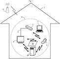
- Fig 1 discloses a local network in the form of a LAN (Local Area Network), typically residing inside a household 1, but may also be e.g. a LAN within a company building/-s and a local network in a vehicle.
- a home local network i.e. a local network at home, may comprise a wired connection 2 between some devices in the home local network, which here is illustrated by an Ethernet cable connection between a displaying device 3 in the form of e.g. a TV unit, an IPTV unit with an STB (Set-Top Box) or a PC (Personal Computer) monitor, and an access point device 4 in the form of e.g. a wireless RGW (Residential Gateway) and Wi-FiTM router.
- a wireless RGW Remote Gateway
- the access point device 4 is typically connected to the Internet, although that is not necessary according to the invention
- devices in the local network are connected to each other via interfaces in a wireless local network 5 in the form of a WLAN or WPAN, e.g. interfaces compatible with IEEE 802.11, IEEE 802.15 or IEEE 802.16 standards, thus forming a LAN part referred to as a HWLAN (Home Wireless LAN) in the following description.
- a wireless local network 5 in the form of a WLAN or WPAN, e.g. interfaces compatible with IEEE 802.11, IEEE 802.15 or IEEE 802.16 standards, thus forming a LAN part referred to as a HWLAN (Home Wireless LAN) in the following description.
- HWLAN Home Wireless LAN
- the UE 6 may within the invention of course also be e.g. a computer in the form of a laptop 7 or a PDA (Portable Digital Assistant).
- Fig 2 shows very schematically an embodiment of the UE 6.
- a display 8 inputting means 9 in the form of e.g. buttons, a processing unit 10 including DSP (Digital Signal Processor) and encoding and decoding modules, a telecommunications interface 11 in the form of a transceiver unit comprising at least one antenna and amplifier adapted for communication with units in a telecommunications network 12 (see Fig 1 ), e.g GSM (Global System for Mobile communications) and/or UMTS (Universal Mobile Telecommunications Standard).
- DSP Digital Signal Processor
- a telecommunications interface 11 in the form of a transceiver unit comprising at least one antenna and amplifier adapted for communication with units in a telecommunications network 12 (see Fig 1 ), e.g GSM (Global System for Mobile communications) and/or UMTS (Universal Mobile Telecommunications Standard).
- GSM Global System for Mobile communications
- UMTS Universal Mobile Telecommunications Standard
- the UE 6 also comprises a communications interface 13 for communication in the wireless local network 5, here in the form of a transceiver adapted for wireless communication with IEEE 802.11 and/or a transceiver 14 adapted for IEEE 802.15. Furthermore the UE 6 comprises at least one computer program product 15 in the form of a non-volatile memory, e.g. an EEPROM and a flash memory.
- the memory comprises a contacts database 16, a computer program 17 being a presence service application and a local network identity database 18 or data storage for storing network names or other information that can be used to identify predefined wireless local networks in a manner to be further discussed below.
- the local network identity database 18 and the contacts database 16 may be separate software in the shown embodiment, they may of course be computer program modules of the presence service application.
- the contacts database 16 may also be a part of a PIM (Personal Information Manager) software. Furthermore, the presence service application may of course be stored on a different memory than e.g. the contacts database 16.
- URL Uniform Resource Locator
- Fig 3 discloses an embodiment of a method to activate a presence service.
- a transceiver of the access point device 4 continuously generates a signal message indicating that the HWLAN is activated.
- the signal message comprises a BSSID (Basic Service Set Identifier) as is known in the art.
- the BSSID is a unique identifier related to a MAC (Media Access Control) address of the access point device.
- a first step D1 the signal message is received by the UE 6 when within the signaling range of the access point device 4.
- the signal message indicates to the UE 6 the presence of the signal message through the BSSID, which also can be shown to a user of the UE 6 via a GUI (Graphical User Interface) in the display 8.
- GUI Graphic User Interface
- the HWLAN is set, i.e. saved, as a first predefined WLAN in the memory, i.e. in the local network identity database 18.
- the first predefined WLAN can therefore be said as being the HWLAN of the UE user.
- Another WLAN may also be set as a second predefined WLAN in the case where the presence service shall be activated in different WLANs, e.g. in the HWLAN at home and another WLAN at work and in a WPAN in a vehicle.
- the GUI may be used to set the HWLAN as the first predefined WLAN by, e.g. displaying a text message on the UE 6 with the essential content of "New WLAN discovered.
- the GUI may comprise an interface where the user directly can input and store the HWLAN including any security keys as the first predefined WLAN if the BSSID is known to the user, even if the UE has not discovered the HWLAN.
- Presence service shall here be understood as a service that automatically is performed when the UE 6 is connected to a certain wireless local network and can be termed as e.g. an "at home service", an "at work service” and "in vehicle service”.
- the presence service application in the UE 6 may in one embodiment comprise code means for a GUI for letting the user activate or deactivate the presence service and associate the presence service to at least one of the predefined WLAN:s; in this example including the HWLAN saved in the second step D2.
- the GUI may in some embodiments let the user define and store other criteria and features for the presence service, as will be more readily understood and explained in the description further down.
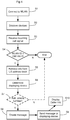
- a first step S1 in Fig 4 the UE 6 is connected to a wireless local network 5 within reach of the communication interface 12 in any of the ways known to a person skilled in the art and is therefore not described more in detail as this is as such known.
- a second step S2 the UE 6 discovers at least one displaying device 3 such as the TV and other video displays, in the WLAN.
- this is achieved with a DLNA/UPnP discovery and description method.
- UPnP is an architecture, developed in a multi-vendor collaboration called the UPnP Forum, for establishing standardised device protocols for the communication between different IP devices in a local network using different access technologies, operating systems, programming languages, format standards and communication protocols.
- UPnP further provides standardised methods to describe and exchange device profiles that may include capabilities, requirements and available services in the devices.
- UPnP and other protocols support a process called “discovery” (or “pairing”) in which a device can join a local network, obtain a local IP address, announce its name and IP address, and exchange capabilities and services with other devices within the local network.
- DLNA is a collaboration between companies to create design guidelines for products so that they can work together in a standardized way, e.g. for storing and accessing digital media content from devices in a local network such as a LAN or PAN.
- the UPnP protocol is utilised by DLNA as an underlying protocol for communication between devices within local networks.
- the UE 6 acts as a UPnP control point and a DMS (Digital Meida Server) and uses UPnP messages to discover what devices that are in reach, i.e. on the same WLAN. This can typically be done by multicasting data about the UE 6 to the other devices or sending a request to the other devices about their capabilities. This is achieved e.g. using SSDP (UPnP Discovery Protocol). Discovered devices may be e.g. DMS (Digital Media Servers) in the form of e.g. PCs (Personal Computers) and NAS (Network Attached Storage) to store content and make the content available to DMPs (Digital Media Players).
- DMS Digital Media Servers
- PCs Personal Computers
- NAS Network Attached Storage
- the displaying devices are in this embodiment known to a person skilled in the art as DMRs (Digital Media Renderers), which also are discovered in this step.
- DMRs Digital Media Renderers
- the discovering process using UPnP is as such known to a person skilled in the art and therefore not described more in detail.
- discovery of the displaying device 3 is conducted within a PAN, using Bluetooth communication instead of any of the IEEE 802.11 standards.
- BluetoothTM pairing also is specified by DLNA and Bluetooth Special Interest Group and is implemented in consumer equipment for sale.
- discovery of the displaying device is made by a Zero Configuration Networking solution known to a person skilled in the art, e.g. a solution which uses multicast DNS (Domain Name System) and DNS Service Discovery.
- a Zero Configuration Networking solution known to a person skilled in the art, e.g. a solution which uses multicast DNS (Domain Name System) and DNS Service Discovery.
- discovery of the displaying device is conducted within a wireless local network according to any of the IEEE 802.16 standards.
- the second step S2 is also conceivable, such as using a discover process according to an Infrared technology standard or using an optional camera in the UE 6 to photograph a QR (Quick Response) code for the displaying device 3 and with reader software in the UE 6 make the UE 6 discover the displaying device 3.
- QR Quick Response
- IP Internet Protocol
- a third step S3 the UE 6 receives an incoming call comprising caller information including at least the telephone number of the caller.
- the call signals may be sent according to e.g. an UTMS or GSM standard.
- a fourth step S4 the presence service application causes the UE 6 to determine if the WLAN ID, e.g. the BSSID, is the same as any of the predefined WLAN IDs stored in the UE, e.g. the HWLAN. If the WLAN ID is not the same as any of the predefined WLAN IDs, no further actions are taken. If the WLAN ID is the same as any one of the predefined WLAN IDs, in this example the ID of the HWLAN, a fifth step S5 is started.
- the WLAN ID e.g. the BSSID
- the presence service application causes the UE 6 to look up the contacts database 16 to determine if there is some more information about the caller other than information associated with the caller that could be derived directly from incoming signals from the telecommunications network 12. Such additional information may e.g. be any of the above mentioned information in the contacts database 16.
- An API Application Programming Interface
- LDAP Lightweight Directory Access Protocol
- a sixth step S6 the presence service application determine if there is any displaying device connected to the HWLAN.
- the presence server application can determine from a device list if there is a DMR connected to the HWLAN and the capability of the DMR.
- a UPnP device description is pre-written by the device vendor, and is typically expressed in XML syntax and based on a standard UPnP Device Template produced by the UPnP Forum working committee.
- To retrieve a UPnP device description of the displaying device 3 the UE may issue an HTTP GET request on the URL in a discovery message, and the displaying device 3 returns the device description. Retrieving a UPnP service description is a similar process that uses a URL within the device description.
- an optional seventh step S7 which could be utilized in some embodiments, it is determined if at least one predetermined criterion in addition to the one in the fourth step S4 is fulfilled in order to continue to an eight step S8.
- the predetermined criterion in the seventh step S7 may be whether or not a predefined displaying device or device model is present in the HWLAN.
- a predefined displaying device or device model is present in the HWLAN.
- Another criterion of the seventh step S7 may be to check whether or not the time is within a predefined time interval.
- caller information may be shown on displaying devices in the HWLAN only during e.g. office hours, within a predefined number of hours from the activation of the presence service application or only at specific days, such as working days.
- Yet another criterion of the seventh step S7 may be to determine if the caller is a predetermined caller for which the presence service shall provide the caller information on the displaying device 3.
- the user of the presence server can differentiate between different persons and situations regarding the expected importance of quickly getting in contact with the caller.
- the eighth step S8 at least one message 19 comprising caller information to the displaying device 3 is created by the UE 6 through the presence service application.
- the message 19 comprises in one embodiment all available caller information received from the contacts database as well as the caller ID received by the UE 6 from the telecommunications network. Hence, if no extra information associated with the caller has been found in the contacts database, the message only contains the information received from the caller.
- the message in addition to the information received from the caller, only comprises extra caller information, if existing, from a limited number of fields in a record associated with the caller in the contacts database 16.
- the determination of fields to be included in the message 19 is in one embodiment determined by the user of the UE 6 via a GUI presented in the display 8 by the presence service application.
- the message 19 is in one embodiment prepared and sent as a text message, e.g. where only caller information that typically is presented as text is retrieved from the contacts database 16.
- the message 19 is in another embodiment prepared as a picture, e.g. a JPEG (Joint Photographic Experts Group), TIFF (Tagged Image File Format), GIF (Graphics Interchange File Format) and PNG (Portable Network Graphics) image, including text and suitably also a picture of the caller if present in the contacts database 16.
- one text message and a picture message is prepared, the picture message being essentially only the picture of the caller in the contacts database 16 and the text message comprising all the other caller information determined to be sent to the displaying device 3.
- Messages prepared in the eighth step S8 shall of course be displayable by the displaying device 3 and as implicitly stated above the UE 6 already in the second step S2 has received the message types/formats that can be displayed by the displaying device 3.
- the message is prepared as a video stream, e.g. in the video formats MPEG-2 (Moving Picture Experts Group 2), MPEG 4, MPEG-4 AVC (MPEG-4 Advanced Video Coding), VC-1, H.263 and MPEG-4 part 2.
- any image, text and video message according to the eighth step S8 may be created in conjunction with an audio message, e.g. in the MP3 and AMR (Adaptive Multi-Rate) format.
- a ninth step S9 the UE 6 transmit/streams the message/image/video and/or the audio message to the displaying device 3.
- This can be done using any standard messaging technique, such as standard HTTP (Hypertext Transfer Protocol) messages used e.g. by DLNA or any HTTP extension for notification according to CEA-2014.
- HTTP Hypertext Transfer Protocol
- the message could be sent as a SIP MESSAGE provided that the message is a text message.
- the displaying device 3 receives the message 19 and displays the caller information.
- the caller information There are several ways to display the caller information known to a person skilled in the art, such as displaying all the received caller information on only a small part of a display of the displaying device 3.
- Another way is to only show a small icon indicating only the incoming call or only a part of the caller information and requiring the user to push a button on a remote control to see all the received caller information.
- a DLNA certified displaying device no adaptation of the displaying device 3 is required as such for receiving the message 19, since a message should not be sent to the displaying device if the UE 6 does not already know that the displaying device 3 is capable of receiving and displaying the content of the message 18.
- the sixth step S6 may, for example, be performed directly after the actions of any one of the second to fifth step S2-S5 or after the actions of the eighth or ninth step, S8 and S9 respectively.
- the checking and determination of the seventh step S7 may, for example, be performed before the fifth step S5.
- the fourth step S4 may of course also be performed before the third step S3 and/or the second step S2.
- some embodiments of the invention comprise a bridging unit 20 (see Fig 1 ) in the HWLAN for bridging between different link-layer bearers as well as content transformation.
- a bridging unit is within the device class MIU (Media Interoperability Unit) and/or M-NCF (Mobile Network Connectivity Function).
Landscapes
- Engineering & Computer Science (AREA)
- Computer Networks & Wireless Communication (AREA)
- Signal Processing (AREA)
- Human Computer Interaction (AREA)
- Mobile Radio Communication Systems (AREA)
Claims (14)
- Verfahren für eine Benutzereinrichtung (6) umfassend eine Kontaktdatenbank (16), wobei die Benutzereinrichtung (6) mit einem Telekommunikationsnetz (12) und mindestens einer Anzeigevorrichtung (3) über ein drahtloses lokales Netzwerk (5) verbunden ist, wobei das Verfahren die folgenden Schritte umfasst:- drahtloses Empfangen (S3) eingehender Anruferinformationen über das Telekommunikatonsnetz (12);- Bestimmen (S5) basierend auf den Anruferinformationen, ob zusätzliche Informationen in der Kontaktdatenbank (16) vorhanden sind, die den Anruferinformationen zugeordnet sind;- Bestimmen (S4), ob ein drahtloser lokaler Netzwerk-Identifikator, WLAN-ID, des drahtlosen lokalen Netzwerks (5) mit einer vorgegebenen Netzwerk-ID identisch ist; und- wenn die WLAN-ID des drahtlosen lokalen Netzwerks mit der vordefinierten Netzwerk-ID übereinstimmt, ausführen der folgenden Schritte:- Erstellen (S8) einer Nachricht, die mindestens einen Teil der empfangenen Anruferinformationen und, falls in der Kontaktdatenbank (16) verfügbar, mindestens einen Teil der zusätzlichen Informationen umfasst; und- Senden (S9) der Nachricht über das drahtlose lokale Netzwerk (5) an die Anzeigevorrichtung (3), sodass die Anzeigevorrichtung (3) mindestens einen Teil der in der Nachricht enthaltenen zusätzlichen Informationen anzeigen kann (S10) .
- Verfahren nach Anspruch 1, umfassend den Schritt des Sendens (S9) der Nachricht als Bilddatei an die Anzeigevorrichtung (3), wobei die Bilddatei ein Bild umfasst, das einem Anrufer zugeordnet und in der Benutzereinrichtung (6) gespeichert ist.
- Verfahren nach Anspruch 1, umfassend den Schritt des Sendens (S9) der zusätzlichen Informationen an die Anzeigevorrichtung (3), die teilweise in einer Textnachricht umfasst sind und teilweise in einer Bilddatei umfasst sind.
- Verfahren nach einem der vorstehenden Ansprüche 1-3, ferner umfassend den Schritt des Ermittelns (S2) der Anzeigevorrichtung (3) durch Senden einer GET-Anforderung des Hypertext-Transfer-Protokolls in einer Ermittlungsnachricht.
- Verfahren nach einem der vorstehenden Ansprüche 1-4, wobei die Nachricht direkt von der Benutzereinrichtung (6) an die Anzeigevorrichtung (3)gesendet wird.
- Verfahren nach einem der vorstehenden Ansprüche 1-4, wobei die Nachricht über eine in dem drahtlosen lokalen Netzwerk (5) umfasste Überbrückungsvorrichtung (20) an die Anzeigevorrichtung (3)gesendet wird.
- Verfahren nach einem der vorstehenden Ansprüche 1-6, umfassend den Schritt, einem Benutzer der Benutzereinrichtung (6) zu ermöglichen, in der Benutzereinrichtung (6) die vorgegebene Netzwerk-ID manuell festzulegen, bevor die eingehenden Anruferinformationen empfangen (S3) werden.
- Computerprogramm (17) für eine Benutzereinrichtung (6), das eine Kontaktdatenbank (16) umfasst und mit einem Telekommunikationsnetz (12) und mindestens einer Anzeigevorrichtung (3) über ein drahtloses lokales Netzwerk (5) verbunden ist, wobei das Computerprogramm (17) ein Kodierungsmittel umfasst, das, wenn es auf der Benutzereinrichtung (6) ausgeführt wird, die Benutzereinrichtung (6) zu Folgendem veranlasst:- Bestimmen (S4), ob eine WLAN-ID des drahtlosen lokalen Netzwerks (5) mit einer vorgegebenen Netzwerk-ID übereinstimmt;- Bestimmen (S5) basierend auf eingehenden Anruferinformationen, die drahtlos über das Telekommunikationsnetz (12) empfangen werden, ob zusätzliche Informationen in der Kontaktdatenbank (16) vorhanden sind, die den Anruferinformationen zugeordnet sind; und- wenn die WLAN-ID des drahtlosen lokalen Netzwerks (5) beim Empfangen der Anruferinformationen durch die Benutzereinrichtung (6) als identisch mit der vordefinierten Netzwerk-ID bestimmt wird, dann wird die Benutzereinrichtung (6) angeordnet zum:- Erstellen (S8) einer Nachricht, die mindestens einen Teil der empfangenen Anruferinformationen und, falls in der Kontaktdatenbank (16) verfügbar, mindestens einen Teil der zusätzlichen Informationen umfasst; und- Senden (S9) der Nachricht über das drahtlose lokale Netzwerk (5) an die Anzeigevorrichtung (3), sodass die Anzeigevorrichtung (3) mindestens einen Teil der in der Nachricht enthaltenen zusätzlichen Informationen anzeigen (S10) kann.
- Computerprogramm (17) nach Anspruch 8, wobei die Nachricht als eine Bilddatei erstellt wird, die, falls verfügbar, ein dem Anrufer zugeordnetes gespeichertes Bild in der Benutzereinrichtung (6) umfasst.
- Computerprogrammprodukt (15), umfassend ein Computerprogramm (17) nach Anspruch 8 und ein computerlesbares Medium, auf dem das Computerprogramm (17) gespeichert ist.
- Benutzereinrichtung (6), umfassend:- eine Kontaktdatenbank (16);- eine Telekommunikationsschnittstelle (11) zur Verbindung mit einem Telekommunikationsnetz (12);- eine Kommunikationsschnittstelle (13) zur Verbindung mit einem drahtlosen lokalen Netzwerk (5); und- eine Verarbeitungseinheit (10), umfassend:- Bestimmungsmittel zum Bestimmen (S4), ob ein drahtloser lokaler Netzwerk-Identifikator, eine WLAN-ID, des drahtlosen lokalen Netzwerks (5) mit einer vorgegebenen Netzwerk-ID identisch ist, wenn eingehende Anruferinformationen drahtlos über das Telekommunikationsnetz (12) empfangen werden, und zum Bestimmen (S5) basierend auf den eingehenden Anruferinformationen, wenn zusätzliche Informationen in der Kontaktdatenbank (16), die den Anruferinformationen zugeordnet sind, vorliegen;- Nachrichtenerstellungsmittel zum Erstellen (S8) einer Nachricht, die mindestens einige der empfangenen Anruferinformationen und, falls in der Kontaktdatenbank (16) verfügbar, mindestens einige der zusätzlichen Informationen umfasst; und- Kommunikationsmittel zum Senden (S9) der Nachricht über das drahtlose lokale Netzwerk (5) über die Kommunikationsschnittstelle (13) an die Anzeigevorrichtung (3), sodass die Anzeigevorrichtung (3) zumindest einen Teil der in der Nachricht enthaltenen zusätzlichen Informationen anzeigen kann.
- Benutzereinrichtung (6) nach Anspruch 11, wobei die Benutzereinrichtung (6) angepasst ist, um einem Benutzer der Benutzereinrichtung (6) zu ermöglichen, ein lokales Netzwerk manuell festzulegen.
- Benutzereinrichtung (6) nach einem der vorstehenden Ansprüche 11-12, wobei die Benutzereinrichtung (6) zur Verbindung mit der Anzeigevorrichtung (3) über Hypertext-Transfer-Protokoll-Nachrichten angepasst ist.
- Benutzereinrichtung (6) nach einem der vorstehenden Ansprüche 11-13, wobei das Nachrichtenerstellungsmittel angepasst ist, um die Nachricht als eine Bilddatei zu erstellen (S8), die, falls verfügbar, ein gespeichertes Bild umfasst, das dem Anrufer in der Benutzereinrichtung (6) zugeordnet ist.
Applications Claiming Priority (1)
| Application Number | Priority Date | Filing Date | Title |
|---|---|---|---|
| PCT/SE2008/050187 WO2009102250A1 (en) | 2008-02-15 | 2008-02-15 | Displaying caller information on wireless local network connected device |
Publications (3)
| Publication Number | Publication Date |
|---|---|
| EP2245840A1 EP2245840A1 (de) | 2010-11-03 |
| EP2245840A4 EP2245840A4 (de) | 2017-05-03 |
| EP2245840B1 true EP2245840B1 (de) | 2018-11-21 |
Family
ID=40957164
Family Applications (1)
| Application Number | Title | Priority Date | Filing Date |
|---|---|---|---|
| EP08712817.9A Not-in-force EP2245840B1 (de) | 2008-02-15 | 2008-02-15 | Anzeigen von anruferinformationen auf einer mit einem drahtlosen lokalen netzwerk verbundenen einrichtung |
Country Status (3)
| Country | Link |
|---|---|
| US (1) | US8798600B2 (de) |
| EP (1) | EP2245840B1 (de) |
| WO (1) | WO2009102250A1 (de) |
Families Citing this family (9)
| Publication number | Priority date | Publication date | Assignee | Title |
|---|---|---|---|---|
| WO2009120030A2 (ko) * | 2008-03-28 | 2009-10-01 | 삼성전자 주식회사 | Iptv 통신 서비스를 제공하는 응용에 대한 정보 수신 방법 및 장치 |
| US8724784B2 (en) * | 2009-04-09 | 2014-05-13 | Echostar Technologies L.L.C. | System and apparatus for transmitting caller identification information |
| US20100310193A1 (en) * | 2009-06-08 | 2010-12-09 | Castleman Mark | Methods and apparatus for selecting and/or displaying images of perspective views of an object at a communication device |
| WO2011085248A1 (en) * | 2010-01-07 | 2011-07-14 | Swakker, Llc | Methods and apparatus for modifying a multimedia object within an instant messaging session at a mobile communication device |
| KR101872551B1 (ko) * | 2011-01-19 | 2018-08-02 | 삼성전자주식회사 | 범용 플러그 앤 플레이 홈 네트워크 환경에서 강화된 이벤트 통지를 제공하는 방법 및 장치 |
| JP5799512B2 (ja) * | 2011-01-31 | 2015-10-28 | ソニー株式会社 | 情報処理装置、および情報処理方法、並びにプログラム |
| EP3334124B1 (de) | 2011-05-26 | 2020-02-05 | Huawei Technologies Co., Ltd. | Verfahren zum mounten einer netzwerkangehängten speichervorrichtung (nas) und korrespondierende set-top-box (stb) |
| US8737977B2 (en) * | 2011-12-20 | 2014-05-27 | Comigo Ltd. | Systems and methods for intergrating telephone communication with computing devices |
| US8958781B2 (en) * | 2012-08-24 | 2015-02-17 | Verizon Patent And Licensing Inc. | Sending caller identification information using a joint services account |
Family Cites Families (8)
| Publication number | Priority date | Publication date | Assignee | Title |
|---|---|---|---|---|
| FI111775B (fi) * | 2000-12-29 | 2003-09-15 | Nokia Corp | Tietoliikennepalvelun tarjoaminen useita verkkoja käsittävässä langattomassa tietoliikennejärjestelmässä |
| DE10132276A1 (de) * | 2001-07-04 | 2003-01-23 | Siemens Ag | System zum Schalten, Steuern, Programmieren und Bedienen von Kommunikationseinrichtungen |
| US20040052341A1 (en) * | 2002-09-18 | 2004-03-18 | I-Hau Yeh | System for automatic notification of caller ID, e-mail identification and short message |
| US7693270B2 (en) * | 2005-12-15 | 2010-04-06 | Alcatel-Lucent Usa Inc. | Method and network for providing service blending to a subscriber |
| US8081970B2 (en) * | 2006-03-27 | 2011-12-20 | Research In Motion Limited | System and method for provisioning a mobile wireless communications device, including indicators representative of image and sound data |
| US8213919B1 (en) * | 2007-03-19 | 2012-07-03 | Sprint Communications Company L.P. | Caller ID handling system for calls placed to a mobile phone |
| US8060068B1 (en) * | 2007-10-10 | 2011-11-15 | Sprint Communications Company L.P. | Interactive mobile caller-identification information on a television |
| US8185139B1 (en) * | 2007-10-11 | 2012-05-22 | Sprint Communications Company L.P. | Presenting mobile-device message information on a television |
-
2008
- 2008-02-15 WO PCT/SE2008/050187 patent/WO2009102250A1/en not_active Ceased
- 2008-02-15 EP EP08712817.9A patent/EP2245840B1/de not_active Not-in-force
- 2008-02-15 US US12/867,653 patent/US8798600B2/en active Active
Non-Patent Citations (1)
| Title |
|---|
| None * |
Also Published As
| Publication number | Publication date |
|---|---|
| WO2009102250A1 (en) | 2009-08-20 |
| EP2245840A1 (de) | 2010-11-03 |
| EP2245840A4 (de) | 2017-05-03 |
| US8798600B2 (en) | 2014-08-05 |
| US20100330970A1 (en) | 2010-12-30 |
Similar Documents
| Publication | Publication Date | Title |
|---|---|---|
| EP2245840B1 (de) | Anzeigen von anruferinformationen auf einer mit einem drahtlosen lokalen netzwerk verbundenen einrichtung | |
| EP2319206B1 (de) | System und verfahren zum senden und empfangen eines anrufs in einem heimnetz | |
| US20070203979A1 (en) | Home communications server | |
| JP4041118B2 (ja) | ゲートウェイ装置、ネットワークシステム、通信プログラム及び通信方法 | |
| US8330598B2 (en) | Aggregated user presence management method within a home network and device for user presence management within a home network | |
| US20070200920A1 (en) | Digital communications adaptor | |
| KR101661210B1 (ko) | Iptv 통신 서비스 수행 방법 및 장치 | |
| US20060031367A1 (en) | Instant messaging and presence using virtual devices | |
| JP5214722B2 (ja) | 通信制御装置、通信装置、送信システム、受信システム、通信システム、通信制御装置の制御方法、通信装置の制御方法、制御プログラム、および、記録媒体 | |
| JP4044551B2 (ja) | ゲートウェイ装置、コンテンツ提供サーバ、通信プログラムおよび通信方法 | |
| US20070127663A1 (en) | Method and system for providing service menu in communication system | |
| JP2005244275A (ja) | ゲートウェイ装置 | |
| JP2010114721A (ja) | ホームネットワーク内の端末から広域ネットワークへコンテンツを送信するコンテンツ送信方法及びシステム | |
| JP4892076B2 (ja) | 通信制御装置、通信制御方法及びプログラム、記録媒体 | |
| JP5191878B2 (ja) | ホームネットワーク内の端末から広域ネットワークへコンテンツを送信するコンテンツ転送方法及びシステム | |
| CN107404591A (zh) | 智能门铃监控方法和装置 | |
| Anand | A DLNA framework for next gen mobile terminals connecting IMS networks for human-centered digital home environment | |
| Rahman et al. | TelephonyArchitecture: 2 | |
| JP2007316926A (ja) | 通信中継装置 |
Legal Events
| Date | Code | Title | Description |
|---|---|---|---|
| PUAI | Public reference made under article 153(3) epc to a published international application that has entered the european phase |
Free format text: ORIGINAL CODE: 0009012 |
|
| 17P | Request for examination filed |
Effective date: 20100905 |
|
| AK | Designated contracting states |
Kind code of ref document: A1 Designated state(s): AT BE BG CH CY CZ DE DK EE ES FI FR GB GR HR HU IE IS IT LI LT LU LV MC MT NL NO PL PT RO SE SI SK TR |
|
| AX | Request for extension of the european patent |
Extension state: AL BA MK RS |
|
| DAX | Request for extension of the european patent (deleted) | ||
| RA4 | Supplementary search report drawn up and despatched (corrected) |
Effective date: 20170331 |
|
| RIC1 | Information provided on ipc code assigned before grant |
Ipc: H04M 1/725 20060101ALI20170327BHEP Ipc: H04W 72/02 20090101ALI20170327BHEP Ipc: H04W 84/12 20090101ALI20170327BHEP Ipc: H04M 1/57 20060101AFI20170327BHEP Ipc: H04W 88/06 20090101ALI20170327BHEP |
|
| GRAP | Despatch of communication of intention to grant a patent |
Free format text: ORIGINAL CODE: EPIDOSNIGR1 |
|
| STAA | Information on the status of an ep patent application or granted ep patent |
Free format text: STATUS: GRANT OF PATENT IS INTENDED |
|
| RIC1 | Information provided on ipc code assigned before grant |
Ipc: H04W 84/12 20090101ALI20180626BHEP Ipc: H04M 1/57 20060101AFI20180626BHEP Ipc: H04W 72/02 20090101ALI20180626BHEP Ipc: H04M 1/725 20060101ALI20180626BHEP Ipc: H04W 88/06 20090101ALI20180626BHEP |
|
| INTG | Intention to grant announced |
Effective date: 20180725 |
|
| GRAS | Grant fee paid |
Free format text: ORIGINAL CODE: EPIDOSNIGR3 |
|
| GRAA | (expected) grant |
Free format text: ORIGINAL CODE: 0009210 |
|
| STAA | Information on the status of an ep patent application or granted ep patent |
Free format text: STATUS: THE PATENT HAS BEEN GRANTED |
|
| AK | Designated contracting states |
Kind code of ref document: B1 Designated state(s): AT BE BG CH CY CZ DE DK EE ES FI FR GB GR HR HU IE IS IT LI LT LU LV MC MT NL NO PL PT RO SE SI SK TR |
|
| REG | Reference to a national code |
Ref country code: CH Ref legal event code: EP |
|
| REG | Reference to a national code |
Ref country code: IE Ref legal event code: FG4D |
|
| REG | Reference to a national code |
Ref country code: DE Ref legal event code: R096 Ref document number: 602008058002 Country of ref document: DE |
|
| REG | Reference to a national code |
Ref country code: AT Ref legal event code: REF Ref document number: 1068917 Country of ref document: AT Kind code of ref document: T Effective date: 20181215 |
|
| REG | Reference to a national code |
Ref country code: NL Ref legal event code: FP |
|
| REG | Reference to a national code |
Ref country code: AT Ref legal event code: MK05 Ref document number: 1068917 Country of ref document: AT Kind code of ref document: T Effective date: 20181121 |
|
| PG25 | Lapsed in a contracting state [announced via postgrant information from national office to epo] |
Ref country code: FI Free format text: LAPSE BECAUSE OF FAILURE TO SUBMIT A TRANSLATION OF THE DESCRIPTION OR TO PAY THE FEE WITHIN THE PRESCRIBED TIME-LIMIT Effective date: 20181121 Ref country code: LV Free format text: LAPSE BECAUSE OF FAILURE TO SUBMIT A TRANSLATION OF THE DESCRIPTION OR TO PAY THE FEE WITHIN THE PRESCRIBED TIME-LIMIT Effective date: 20181121 Ref country code: HR Free format text: LAPSE BECAUSE OF FAILURE TO SUBMIT A TRANSLATION OF THE DESCRIPTION OR TO PAY THE FEE WITHIN THE PRESCRIBED TIME-LIMIT Effective date: 20181121 Ref country code: LT Free format text: LAPSE BECAUSE OF FAILURE TO SUBMIT A TRANSLATION OF THE DESCRIPTION OR TO PAY THE FEE WITHIN THE PRESCRIBED TIME-LIMIT Effective date: 20181121 Ref country code: BG Free format text: LAPSE BECAUSE OF FAILURE TO SUBMIT A TRANSLATION OF THE DESCRIPTION OR TO PAY THE FEE WITHIN THE PRESCRIBED TIME-LIMIT Effective date: 20190221 Ref country code: AT Free format text: LAPSE BECAUSE OF FAILURE TO SUBMIT A TRANSLATION OF THE DESCRIPTION OR TO PAY THE FEE WITHIN THE PRESCRIBED TIME-LIMIT Effective date: 20181121 Ref country code: ES Free format text: LAPSE BECAUSE OF FAILURE TO SUBMIT A TRANSLATION OF THE DESCRIPTION OR TO PAY THE FEE WITHIN THE PRESCRIBED TIME-LIMIT Effective date: 20181121 Ref country code: NO Free format text: LAPSE BECAUSE OF FAILURE TO SUBMIT A TRANSLATION OF THE DESCRIPTION OR TO PAY THE FEE WITHIN THE PRESCRIBED TIME-LIMIT Effective date: 20190221 Ref country code: IS Free format text: LAPSE BECAUSE OF FAILURE TO SUBMIT A TRANSLATION OF THE DESCRIPTION OR TO PAY THE FEE WITHIN THE PRESCRIBED TIME-LIMIT Effective date: 20190321 |
|
| PG25 | Lapsed in a contracting state [announced via postgrant information from national office to epo] |
Ref country code: GR Free format text: LAPSE BECAUSE OF FAILURE TO SUBMIT A TRANSLATION OF THE DESCRIPTION OR TO PAY THE FEE WITHIN THE PRESCRIBED TIME-LIMIT Effective date: 20190222 Ref country code: PT Free format text: LAPSE BECAUSE OF FAILURE TO SUBMIT A TRANSLATION OF THE DESCRIPTION OR TO PAY THE FEE WITHIN THE PRESCRIBED TIME-LIMIT Effective date: 20190321 Ref country code: SE Free format text: LAPSE BECAUSE OF FAILURE TO SUBMIT A TRANSLATION OF THE DESCRIPTION OR TO PAY THE FEE WITHIN THE PRESCRIBED TIME-LIMIT Effective date: 20181121 |
|
| PG25 | Lapsed in a contracting state [announced via postgrant information from national office to epo] |
Ref country code: IT Free format text: LAPSE BECAUSE OF FAILURE TO SUBMIT A TRANSLATION OF THE DESCRIPTION OR TO PAY THE FEE WITHIN THE PRESCRIBED TIME-LIMIT Effective date: 20181121 Ref country code: CZ Free format text: LAPSE BECAUSE OF FAILURE TO SUBMIT A TRANSLATION OF THE DESCRIPTION OR TO PAY THE FEE WITHIN THE PRESCRIBED TIME-LIMIT Effective date: 20181121 Ref country code: PL Free format text: LAPSE BECAUSE OF FAILURE TO SUBMIT A TRANSLATION OF THE DESCRIPTION OR TO PAY THE FEE WITHIN THE PRESCRIBED TIME-LIMIT Effective date: 20181121 Ref country code: DK Free format text: LAPSE BECAUSE OF FAILURE TO SUBMIT A TRANSLATION OF THE DESCRIPTION OR TO PAY THE FEE WITHIN THE PRESCRIBED TIME-LIMIT Effective date: 20181121 |
|
| REG | Reference to a national code |
Ref country code: DE Ref legal event code: R097 Ref document number: 602008058002 Country of ref document: DE |
|
| PG25 | Lapsed in a contracting state [announced via postgrant information from national office to epo] |
Ref country code: EE Free format text: LAPSE BECAUSE OF FAILURE TO SUBMIT A TRANSLATION OF THE DESCRIPTION OR TO PAY THE FEE WITHIN THE PRESCRIBED TIME-LIMIT Effective date: 20181121 Ref country code: SK Free format text: LAPSE BECAUSE OF FAILURE TO SUBMIT A TRANSLATION OF THE DESCRIPTION OR TO PAY THE FEE WITHIN THE PRESCRIBED TIME-LIMIT Effective date: 20181121 Ref country code: RO Free format text: LAPSE BECAUSE OF FAILURE TO SUBMIT A TRANSLATION OF THE DESCRIPTION OR TO PAY THE FEE WITHIN THE PRESCRIBED TIME-LIMIT Effective date: 20181121 |
|
| PLBE | No opposition filed within time limit |
Free format text: ORIGINAL CODE: 0009261 |
|
| STAA | Information on the status of an ep patent application or granted ep patent |
Free format text: STATUS: NO OPPOSITION FILED WITHIN TIME LIMIT |
|
| REG | Reference to a national code |
Ref country code: CH Ref legal event code: PL |
|
| 26N | No opposition filed |
Effective date: 20190822 |
|
| PG25 | Lapsed in a contracting state [announced via postgrant information from national office to epo] |
Ref country code: LU Free format text: LAPSE BECAUSE OF NON-PAYMENT OF DUE FEES Effective date: 20190215 Ref country code: SI Free format text: LAPSE BECAUSE OF FAILURE TO SUBMIT A TRANSLATION OF THE DESCRIPTION OR TO PAY THE FEE WITHIN THE PRESCRIBED TIME-LIMIT Effective date: 20181121 Ref country code: MC Free format text: LAPSE BECAUSE OF FAILURE TO SUBMIT A TRANSLATION OF THE DESCRIPTION OR TO PAY THE FEE WITHIN THE PRESCRIBED TIME-LIMIT Effective date: 20181121 |
|
| REG | Reference to a national code |
Ref country code: BE Ref legal event code: MM Effective date: 20190228 |
|
| REG | Reference to a national code |
Ref country code: IE Ref legal event code: MM4A |
|
| PG25 | Lapsed in a contracting state [announced via postgrant information from national office to epo] |
Ref country code: LI Free format text: LAPSE BECAUSE OF NON-PAYMENT OF DUE FEES Effective date: 20190228 Ref country code: CH Free format text: LAPSE BECAUSE OF NON-PAYMENT OF DUE FEES Effective date: 20190228 |
|
| PG25 | Lapsed in a contracting state [announced via postgrant information from national office to epo] |
Ref country code: IE Free format text: LAPSE BECAUSE OF NON-PAYMENT OF DUE FEES Effective date: 20190215 |
|
| PG25 | Lapsed in a contracting state [announced via postgrant information from national office to epo] |
Ref country code: FR Free format text: LAPSE BECAUSE OF NON-PAYMENT OF DUE FEES Effective date: 20190228 Ref country code: BE Free format text: LAPSE BECAUSE OF NON-PAYMENT OF DUE FEES Effective date: 20190228 |
|
| PG25 | Lapsed in a contracting state [announced via postgrant information from national office to epo] |
Ref country code: TR Free format text: LAPSE BECAUSE OF FAILURE TO SUBMIT A TRANSLATION OF THE DESCRIPTION OR TO PAY THE FEE WITHIN THE PRESCRIBED TIME-LIMIT Effective date: 20181121 |
|
| PGFP | Annual fee paid to national office [announced via postgrant information from national office to epo] |
Ref country code: DE Payment date: 20200227 Year of fee payment: 13 Ref country code: NL Payment date: 20200226 Year of fee payment: 13 Ref country code: GB Payment date: 20200227 Year of fee payment: 13 |
|
| PG25 | Lapsed in a contracting state [announced via postgrant information from national office to epo] |
Ref country code: MT Free format text: LAPSE BECAUSE OF NON-PAYMENT OF DUE FEES Effective date: 20190215 |
|
| PG25 | Lapsed in a contracting state [announced via postgrant information from national office to epo] |
Ref country code: CY Free format text: LAPSE BECAUSE OF FAILURE TO SUBMIT A TRANSLATION OF THE DESCRIPTION OR TO PAY THE FEE WITHIN THE PRESCRIBED TIME-LIMIT Effective date: 20181121 |
|
| PG25 | Lapsed in a contracting state [announced via postgrant information from national office to epo] |
Ref country code: HU Free format text: LAPSE BECAUSE OF FAILURE TO SUBMIT A TRANSLATION OF THE DESCRIPTION OR TO PAY THE FEE WITHIN THE PRESCRIBED TIME-LIMIT; INVALID AB INITIO Effective date: 20080215 |
|
| REG | Reference to a national code |
Ref country code: DE Ref legal event code: R119 Ref document number: 602008058002 Country of ref document: DE |
|
| GBPC | Gb: european patent ceased through non-payment of renewal fee |
Effective date: 20210215 |
|
| REG | Reference to a national code |
Ref country code: NL Ref legal event code: MM Effective date: 20210301 |
|
| PG25 | Lapsed in a contracting state [announced via postgrant information from national office to epo] |
Ref country code: NL Free format text: LAPSE BECAUSE OF NON-PAYMENT OF DUE FEES Effective date: 20210301 |
|
| PG25 | Lapsed in a contracting state [announced via postgrant information from national office to epo] |
Ref country code: DE Free format text: LAPSE BECAUSE OF NON-PAYMENT OF DUE FEES Effective date: 20210901 Ref country code: GB Free format text: LAPSE BECAUSE OF NON-PAYMENT OF DUE FEES Effective date: 20210215 |