EP2245955B1 - Hybrid epilator device - Google Patents
Hybrid epilator device Download PDFInfo
- Publication number
- EP2245955B1 EP2245955B1 EP09005818A EP09005818A EP2245955B1 EP 2245955 B1 EP2245955 B1 EP 2245955B1 EP 09005818 A EP09005818 A EP 09005818A EP 09005818 A EP09005818 A EP 09005818A EP 2245955 B1 EP2245955 B1 EP 2245955B1
- Authority
- EP
- European Patent Office
- Prior art keywords
- adjustment
- epilation
- epilator device
- displacement
- razor blade
- Prior art date
- Legal status (The legal status is an assumption and is not a legal conclusion. Google has not performed a legal analysis and makes no representation as to the accuracy of the status listed.)
- Active
Links
Images


Classifications
-
- A—HUMAN NECESSITIES
- A45—HAND OR TRAVELLING ARTICLES
- A45D—HAIRDRESSING OR SHAVING EQUIPMENT; EQUIPMENT FOR COSMETICS OR COSMETIC TREATMENTS, e.g. FOR MANICURING OR PEDICURING
- A45D26/00—Hair-singeing apparatus; Apparatus for removing superfluous hair, e.g. tweezers
- A45D26/0061—Hair-singeing apparatus; Apparatus for removing superfluous hair, e.g. tweezers with means for reducing pain during hair removal
-
- A—HUMAN NECESSITIES
- A45—HAND OR TRAVELLING ARTICLES
- A45D—HAIRDRESSING OR SHAVING EQUIPMENT; EQUIPMENT FOR COSMETICS OR COSMETIC TREATMENTS, e.g. FOR MANICURING OR PEDICURING
- A45D26/00—Hair-singeing apparatus; Apparatus for removing superfluous hair, e.g. tweezers
- A45D26/0023—Hair-singeing apparatus; Apparatus for removing superfluous hair, e.g. tweezers with rotating clamping elements
- A45D26/0028—Hair-singeing apparatus; Apparatus for removing superfluous hair, e.g. tweezers with rotating clamping elements with rotating discs or blades
Definitions
- the present invention is concerned with a hybrid epilator device and in particular with a hybrid epilator device that comprises a razor blade.
- a hybrid epilator device comprising a razor blade was first described in German patent application No. 102007050661.0-23 .
- Such a hybrid epilator device is given in accordance with claim 1. Further embodiments are given in accordance with the dependent claims.
- the hybrid epilator device as proposed comprises at least a razor blade that has a sharp edge for shaving off hairs growing on a skin surface and an epilation cylinder intended for driven rotation around its cylinder axis that comprises at least a pair of clamping elements that are arranged to be actuated by an actuation system during operation between an open position in which a gap is present between the clamping elements so that hairs can feed into the gap and a closed position in which the clamping elements are in tight contact so that hairs that were present in the gap are firmly gripped and plucked out of the skin surface when the epilation cylinder rotates.
- the razor blade is arranged behind the epilation cylinder with respect to a use direction that is defined by the sharp edge of the razor blade.
- a circumferential part of the epilation cylinder and the sharp edge of the razor blade define a skin contact surface along which the hybrid epilator device is to be drawn over the skin surface to effectuate successive plucking out of hairs and shaving off of hairs that still remain on the epilated skin surface.
- the skin contact surface defined by the device coincides with the skin surface.
- the closed position of the pair of clamping elements will be assumed with a certain angle with respect to the skin contact surface (or the skin surface).
- the hybrid epilator device further comprises a manually operable adjustment mechanism that has at least a first adjustment and a second adjustment such that the sharp edge of the razor blade and the circumferential part of the epilation cylinder can simultaneously contact the skin surface during operation in the first adjustment and in the second adjustment, but the angular position at which the closed position of the clamping elements is assumed with respect to the skin contact surface (or: skin surface during operation) is different in the first adjustment and in the second adjustment.
- the epilation efficiency (the epilation efficiency being defined as the number of hairs being plucked out from a skin surface area in a single stroke vs. the number of hairs growing on the skin surface area before epilation treatment) of the epilation cylinder depends on the angle at which the closed position is assumed.
- the proposed hybrid epilator device allows for adjusting the epilation efficiency by the manually operable adjustment mechanism and hence the ratio between plucked out hairs vs. shaved off hairs.
- the latter hair removal process being essentially pain free, so that the proposed hybrid epilator device allows for complete hair removal in a single stroke (it can be assumed that the razor blade will shave off all hairs that remain on the skin surface after epilation) with an adjustable epilation ratio (in other words: an adjustable pain level).
- the manually operable adjustment mechanism comprises a mounting structure at which the razor blade is mounted, which mounting structure is movable at least between a first position and a second position, where the manually operable adjustment mechanism is in its first adjustment when the mounting structure is in the first position and its second adjustment when the mounting structure is in its second position.
- the mounting structure is arranged pivotable around the cylinder axis of the epilation axis. The movable mounting structure can be arranged so as to snap into the first position and the second position.
- the manually operable adjustment mechanism comprises a displacement mechanism that is arranged to be switchable between at least a first displacement and a second displacement.
- the manually operable adjustment mechanism assumes the first adjustment when the displacement mechanism is in the first displacement and the second adjustment when the displacement mechanism is in the second displacement.
- the displacement mechanism displaces at least a part of the actuation system. Specifically, the displacement mechanism rotates the part of the actuation system around the cylinder axis of the epilation cylinder.
- the razor blade is mounted in a cartridge.
- the razor blade is floatingly or rotatably mounted so that the razor blade can adapt to uneven skin surfaces and stay in contact with the skin while the hybrid epilator device is drawn over the skin.
- Fig. 1 is a schematic depiction of an epilator device 100' as generally known in the art.
- the epilator device 100' comprises a housing 101 at which an epilation unit 10 is mounted as is known in the art; e.g. international patent application WO 2006/037392 A1 , the respective content of which is incorporated herein by reference, describes such a typical epilation unit 10 and its mounting arrangement.
- the epilation unit 10 is arranged for gripping and plucking out hairs 91 growing on a skin surface 90 during regular operation of the epilator device 100'.
- the epilation unit 10 comprises an epilation cylinder 11 that has axially and circumferentially spaced pairs of clamping elements 12 arranged on its cylinder surface.
- the epilation cylinder 11 rotates around its cylinder axis 13 in the direction R as indicated by an arrow.
- the epilator device 100' is drawn in the preferred use direction U P over the skin surface 90 to grip and pluck out hairs 91.
- An actuation system (details of the actuation system are discussed with reference to Fig. 5 below), as is e.g.
- the clamping elements 12 assume the closed position at an angular position ⁇ with respect to a coordinate system (indicated by dashed lines x and y) fixed at the housing 101 and with origin in the cylinder axis 13.
- the angular position ⁇ at which the closed position is assumed is usually optimized for high epilation efficiency (the epilation efficiency being defined as the number of hairs being plucked out from a skin surface area in a single stroke vs. the number of hairs growing on the skin surface area before epilation treatment).
- Achieving optimal epilation efficiency requires that the epilator device 100' is placed on the skin surface 90 with a certain advised angle so that the clamping elements 12 also assume the closed position at the angular position ⁇ with respect to the skin surface 90 as the coordinate system is then considered to be fixed to a planar skin surface 90.
- Fig. 2 is a schematic depiction of an exemplary embodiment of a hybrid epilator device 100 as proposed.
- the hybrid epilator device 100 comprises an epilation unit 10 as discussed with reference to Fig. 1 and further comprises at least a razor blade 80, where in the embodiment shown in Fig. 2 three razor blades 80 are mounted in a cartridge 81.
- the cartridge 81 may be realized as a standard razor blade cartridge as is generally known in the art of safety razors.
- the cartridge 81 is part of a mounting structure 110 that is mounted to the housing 101 of the hybrid epilator device 100.
- the mounting structure 110 may be arranged so that it can be pivoted around cylinder axis 13 of the epilation cylinder 11.
- the mounting structure 110 is shown in Fig.
- the mounting structure 110 may snap into the first position and into the second position, e.g. by providing respective recesses in the housing 101 into which projections of the mounting structure 110 snap in.
- the mounting structure 110 thus allows adjusting the angular position ⁇ at which the closed position of the pair of clamping elements 12 is assumed with respect to the skin surface 90.
- the cartridge 81 may be a fixedly mounted part of the mounting structure 110 or the cartridge 81 may be a pivotable and/or floatable part of the mounting structure 110 so that the razor blade 80 can adapt its contact to uneven skin surface topology. It is to be understood that in all embodiments of the hybrid epilator device 100, a single razor blade 80 can be present or two, three (as shown), four, or five etc. razor blades 80 could be present.
- the razor blade 80 has a sharp edge for shaving off hairs 91 from the skin surface 90 when the hybrid epilator device 100 is drawn over the skin surface 90 along a use direction U.
- the razor blade 80 is mounted behind the epilation unit 10 with respect to the use direction U.
- the epilation unit 10 and the razor blade 80 are mounted for simultaneous contact of the skin surface 90 so that in operation the epilation unit 10 first grips and plucks out hairs 91 from the skin surface 90 and then the razor blade 80 shaves off remaining hairs 91 still growing on the skin surface 90 in the same stroke.
- the hybrid epilator device 100 further comprises a displacement mechanism 19 for adjusting the angular position ⁇ at which the closed position is achieved.
- the displacement mechanism 19 can be switched from a first displacement position that is shown in Fig. 2 to a second displacement position, which is shown in and described with reference to Fig. 3B .
- the displacement mechanism could rotate a pressure plate (defining the closed position of the clamping elements) being part of an actuation system so that the angular position ⁇ would then also be rotated (this is discussed in more detail with respect to Fig. 5 ).
- a pressure plate defining the closed position of the clamping elements
- the mounting structure 110 may have skin contact faces 111 that together with the razor blade 80 define the skin contact plane at which the hybrid epilator device 100 has to contact the skin surface 90 so that simultaneous plucking out and shaving off of hairs is effectuated.
- An epilation unit 10 as known in the art may have an epilation efficiency of up to about 90%, which means that nine out of ten hairs 91 are gripped and plucked out from the skin surface 90 in a single stroke of the hybrid epilator device 100 (the epilation efficiency is hence the ratio of the number of plucked out hairs in a single stroke over a certain skin surface area and the number of hairs present on the skin surface area before epilation). It can now be assumed without prejudice that the razor blade 80 shaves off all remaining hairs 91 that were not plucked out by the epilation unit 10 in the same single stroke. Hence, the hybrid epilator device 100 has a hair removal efficiency of 100%.
- the hybrid epilator device 100 specifically when used in a wet environment, e.g. in combination with a shaving lotion, generates a gentle and smooth skin feeling that is not reached with a pure epilator device, as the razor blade 80 also abrades top skin parts.
- a hybrid epilator device 100 is hence specifically fast in achieving complete hair removal on a certain skin surface area (e.g. a leg) and it also reduces the pain involved with plucking out hairs as hairs not plucked out in the first stroke are shaved off.
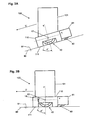
- Fig. 3A is a schematic depiction of the hybrid epilator device 100 as shown in Fig. 2 , where the mounting structure 110 is moved into a second position by pivoting the mounting structure 110 around the cylinder axis 13. In this second position, the razor blade a 80 and the epilation unit 10 can still simultaneously contact the skin surface 90, but the angular position ⁇ ' at which the closed position of the clamping elements is assumed is changed to a larger angle with respect to the skin surface 90 (or with respect to the coordinate system - indicated by dashed lines x and y - that is fixed to the mounting structure 110).
- the closed position is now assumed at an angular position ⁇ ' at which the clamping elements 12 have moved farther away from the skin surface 90 in contrast to the angular position ⁇ as shown in Fig. 2 .
- ⁇ ' shown in Fig. 3A
- hairs 91 that have fed into the gap between the clamping elements 12 in the open position may have slipped out of the gap already before the closed position is assumed.
- the epilation efficiency of the epilation unit 10 has dropped when compared to the efficiency of the epilation unit 10 when the razor blade 80 is in the first position ( Fig. 2 ).
- the proposed hybrid epilator device 100 thus allows that the ratio R is modified by the user through a simple rotation of the mounting structure 110 from a first rotation position to a second rotation position (which also moves the razor blade 80 from a first position to a second position) and thus the plucking pain involved with complete hair removal is changed and can be adapted to the individual preferences.
- Fig. 3B is a schematic depiction of the hybrid epilator device 100 shown in Fig. 2 but with the displacement mechanism 19 being locked into a second displacement.
- the displacement mechanism 19 as discussed here may comprise a lever that acts on pressure plates of an actuation system such that the pressure plates are rotated around the cylinder axis 13 when switching the displacement mechanism 19 from the first displacement to the second displacement.
- the angular position ⁇ " at which the closed position of the clamping elements 12 is assumed in the second displacement is shifted to a larger angle with respect to the skin surface 90 in operation.
- the shift of the angular position ⁇ " at which the closed position of the pair of clamping elements 12 is assumed leads to a lower epilation efficiency of the epilation unit 10 and hence to an adjustment of the ratio of the number of hairs that are plucked out from the skin surface vs. the number of (remaining) hairs that are shaved off.
- the manually operable adjustment mechanism comprises a mounting structure that can be moved between a first and a second position, where the first position relates to the first adjustment of the angular position and the second position relates to the second adjustment.
- the manually operable adjustment mechanism comprises a displacement mechanism that can be switched from a first displacement to a second displacement, where the first displacement relates to the first adjustment of the angular position and the second displacement relates to the second adjustment.
- the epilation unit 10 is arranged to be displaceable, i.e. a manually operable adjustment system (here: this may be realized as a simple lever that extends through the housing and which lever is coupled to the epilation unit 10) moves the epilation unit 10 such that a distance between the outer surface of the epilation unit 10 and a skin contact surface defined by the skin contact face 111 and the sharp edge of the razor blade 80 can be achieved.
- a manually operable adjustment system here: this may be realized as a simple lever that extends through the housing and which lever is coupled to the epilation unit 10.
- Fig. 4 is a depiction of a realization of an exemplary embodiment of a hybrid epilator device 100 as proposed.
- the hybrid epilator device 100 has a housing 101 and an epilation unit 10 mounted at a head region of the housing 101.
- a mounting structure 110 is mounted to the housing 101 so as to provide an aperture into which the epilation cylinder 11 of the epilation unit 10 extends and so as to be pivotable around the cylinder axis 13 (indicated by a dashed-dotted line) of the epilation cylinder 11.
- Several razor blades 80 are mounted directly at the mounting structure 110 and are provided for simultaneous contact with the skin surface together with the epilation cylinder 11.
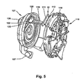
- Fig. 5 shows components of an exemplary embodiment of an epilation cylinder and an actuation system, which exemplary embodiment is discussed in WO 2006/037391 A1 , in the form of a perspective representation. Only one rod 119 for actuating a movable clamping element 111 of a pair of clamping elements 12 is respectively illustrated in Fig. 5 so as to provide a better overview.
- the actuation rods 119 extend through holes 118 that are provided in discs 110 that form the epilation cylinder.
- a holding arrangement 126 is provided for a bow spring that will press discs 110 and pressure plates 121 together (the epilation cylinder consists of several discs 110 and two pressure discs 121 are arranged at the ends of the epilation cylinder).
- the epilation cylinder comprising the discs 110 and the actuation rods 119 rotates, while the pressure plates 121 are fixed with respect to the housing of the hybrid epilator device.
- a pressure element 122 provided on the inner face of the pressure plate 121 is shaped such that a control surface 123 forms an elevation that, referred to the circumferential direction of the pressure plate 121, begins in the form of a steadily ascending ramp and ends in a steadily descending ramp.
- a head part 120 of the actuation rod 119 moves along the control surface 123 of the pressure plate 121 and the clamping element 111 coupled to the actuation rod 119 is pressed against a non-movable clamping element 112 so that the clamping elements 111 and 112 assume a closed position at a certain angular position that is defined by the relative position of the pressure plate 121 to the housing of the hybrid epilator device.
- the displacement mechanism 19 as discussed with reference to Figs. 2 and 3B may act on a lever 127 and thus can rotate the pressure plate 121 (and its respective counterpart arranged at the opposite end of the epilation cylinder) when the displacement mechanism is switched from a first displacement to a second displacement.
Landscapes
- Health & Medical Sciences (AREA)
- General Health & Medical Sciences (AREA)
- Pain & Pain Management (AREA)
- Dry Shavers And Clippers (AREA)
- Surgical Instruments (AREA)
- Cosmetics (AREA)
Priority Applications (10)
| Application Number | Priority Date | Filing Date | Title |
|---|---|---|---|
| PL09005818T PL2245955T3 (pl) | 2009-04-27 | 2009-04-27 | Hybrydowy depilator |
| ES09005818T ES2386599T3 (es) | 2009-04-27 | 2009-04-27 | Dispositivo depilador híbrido |
| EP09005818A EP2245955B1 (en) | 2009-04-27 | 2009-04-27 | Hybrid epilator device |
| CN201080018519.2A CN102413728B (zh) | 2009-04-27 | 2010-04-27 | 混合脱毛器装置 |
| JP2012505295A JP5420753B2 (ja) | 2009-04-27 | 2010-04-27 | ハイブリッド脱毛装置 |
| RU2011139498/12A RU2476132C1 (ru) | 2009-04-27 | 2010-04-27 | Гибридное эпиляционное устройство |
| BRPI1015348A BRPI1015348A2 (pt) | 2009-04-27 | 2010-04-27 | dispositivo epilador híbrido |
| EP10717857A EP2424401A1 (en) | 2009-04-27 | 2010-04-27 | Hybrid epilator device |
| PCT/IB2010/051837 WO2010125521A1 (en) | 2009-04-27 | 2010-04-27 | Hybrid epilator device |
| US13/282,231 US8870896B2 (en) | 2009-04-27 | 2011-10-26 | Hybrid epilator device |
Applications Claiming Priority (1)
| Application Number | Priority Date | Filing Date | Title |
|---|---|---|---|
| EP09005818A EP2245955B1 (en) | 2009-04-27 | 2009-04-27 | Hybrid epilator device |
Publications (2)
| Publication Number | Publication Date |
|---|---|
| EP2245955A1 EP2245955A1 (en) | 2010-11-03 |
| EP2245955B1 true EP2245955B1 (en) | 2012-07-11 |
Family
ID=40897292
Family Applications (2)
| Application Number | Title | Priority Date | Filing Date |
|---|---|---|---|
| EP09005818A Active EP2245955B1 (en) | 2009-04-27 | 2009-04-27 | Hybrid epilator device |
| EP10717857A Withdrawn EP2424401A1 (en) | 2009-04-27 | 2010-04-27 | Hybrid epilator device |
Family Applications After (1)
| Application Number | Title | Priority Date | Filing Date |
|---|---|---|---|
| EP10717857A Withdrawn EP2424401A1 (en) | 2009-04-27 | 2010-04-27 | Hybrid epilator device |
Country Status (9)
| Country | Link |
|---|---|
| US (1) | US8870896B2 (pt) |
| EP (2) | EP2245955B1 (pt) |
| JP (1) | JP5420753B2 (pt) |
| CN (1) | CN102413728B (pt) |
| BR (1) | BRPI1015348A2 (pt) |
| ES (1) | ES2386599T3 (pt) |
| PL (1) | PL2245955T3 (pt) |
| RU (1) | RU2476132C1 (pt) |
| WO (1) | WO2010125521A1 (pt) |
Families Citing this family (8)
| Publication number | Priority date | Publication date | Assignee | Title |
|---|---|---|---|---|
| EP2220958B1 (en) * | 2009-02-18 | 2016-10-05 | Braun GmbH | Epilator with an attachment and such attachment |
| US9320335B2 (en) * | 2013-12-30 | 2016-04-26 | L'oreal | Grooming devices and methods therefor |
| FR3025983B1 (fr) * | 2014-09-19 | 2017-11-24 | Seb Sa | Appareil de traitement de la peau a elements vibrants |
| CN109922747B (zh) | 2016-11-11 | 2023-05-26 | 皇家飞利浦有限公司 | 用于去除胼胝的设备 |
| ES2790127T3 (es) * | 2017-06-23 | 2020-10-27 | Braun Gmbh | Depiladora |
| EP3689180B1 (en) | 2017-10-06 | 2021-11-03 | Braun GmbH | Epilator |
| CN108908418B (zh) * | 2018-06-19 | 2020-08-07 | 赵伟 | 一种用于神经外科的自走拉伸型备皮装置 |
| EP3632259A1 (en) * | 2018-10-03 | 2020-04-08 | Koninklijke Philips N.V. | An epilating device for epilating hair |
Family Cites Families (19)
| Publication number | Priority date | Publication date | Assignee | Title |
|---|---|---|---|---|
| JPS56100088A (en) * | 1980-01-11 | 1981-08-11 | Matsushita Electric Works Ltd | Razor device |
| US5050301A (en) * | 1990-09-19 | 1991-09-24 | The Gillette Company | Razor assembly |
| JPH04269993A (ja) * | 1991-02-25 | 1992-09-25 | Matsushita Electric Works Ltd | 電気かみそり |
| JP3427212B2 (ja) * | 1992-11-13 | 2003-07-14 | 松下電工株式会社 | 往復式電気かみそり |
| US5507753A (en) * | 1993-04-15 | 1996-04-16 | Matsushita Electric Works, Ltd. | Depilating device with skin guide stretcher |
| JP3391956B2 (ja) * | 1995-10-13 | 2003-03-31 | 松下電工株式会社 | 除毛装置 |
| EP0944459A1 (en) * | 1996-08-16 | 1999-09-29 | Koninklijke Philips Electronics N.V. | Hair removal appliance with adjustable hair extraction distance |
| CN1204978A (zh) * | 1996-08-16 | 1999-01-13 | 菲利浦电子有限公司 | 可以调节毛发拔出距离的除毛器具 |
| JP3899696B2 (ja) * | 1998-08-26 | 2007-03-28 | 松下電工株式会社 | 脱毛装置 |
| DE19932884C1 (de) * | 1999-07-16 | 2000-08-10 | Braun Gmbh | Epilationsgerät |
| FR2823080B1 (fr) * | 2001-04-06 | 2003-05-30 | Seb Sa | Appareil a epiler |
| MXPA05000423A (es) * | 2003-03-13 | 2005-03-23 | Radiancy Inc | Rasuradora electrica con cabeza vibratoria. |
| FR2858528B1 (fr) * | 2003-08-08 | 2005-09-09 | Seb Sa | Appareil a epiler a pinces d'arrachage |
| CN1968618A (zh) * | 2004-06-14 | 2007-05-23 | 皇家飞利浦电子股份有限公司 | 具有可移动冷却表面的个人护理系统 |
| DE102004047873A1 (de) | 2004-10-01 | 2006-04-06 | Braun Gmbh | Epilationskopf und Epilationsgerät |
| DE102004047874A1 (de) | 2004-10-01 | 2006-04-06 | Braun Gmbh | Epilationskopf und Epilationsgerät |
| DE102005045713A1 (de) * | 2005-09-24 | 2007-03-29 | Braun Gmbh | Elektrisches Haarentfernungsgerät |
| FR2892902B1 (fr) * | 2005-11-07 | 2007-12-14 | Seb Sa | Appareil a epiler comportant un dispositif de coupe des poils. |
| DE102007050661A1 (de) | 2007-10-24 | 2009-04-30 | Braun Gmbh | Epiliergerät |
-
2009
- 2009-04-27 ES ES09005818T patent/ES2386599T3/es active Active
- 2009-04-27 EP EP09005818A patent/EP2245955B1/en active Active
- 2009-04-27 PL PL09005818T patent/PL2245955T3/pl unknown
-
2010
- 2010-04-27 RU RU2011139498/12A patent/RU2476132C1/ru not_active IP Right Cessation
- 2010-04-27 WO PCT/IB2010/051837 patent/WO2010125521A1/en not_active Ceased
- 2010-04-27 BR BRPI1015348A patent/BRPI1015348A2/pt not_active IP Right Cessation
- 2010-04-27 JP JP2012505295A patent/JP5420753B2/ja not_active Expired - Fee Related
- 2010-04-27 EP EP10717857A patent/EP2424401A1/en not_active Withdrawn
- 2010-04-27 CN CN201080018519.2A patent/CN102413728B/zh not_active Expired - Fee Related
-
2011
- 2011-10-26 US US13/282,231 patent/US8870896B2/en not_active Expired - Fee Related
Also Published As
| Publication number | Publication date |
|---|---|
| JP5420753B2 (ja) | 2014-02-19 |
| EP2424401A1 (en) | 2012-03-07 |
| BRPI1015348A2 (pt) | 2016-04-19 |
| US8870896B2 (en) | 2014-10-28 |
| CN102413728A (zh) | 2012-04-11 |
| CN102413728B (zh) | 2015-08-26 |
| PL2245955T3 (pl) | 2013-02-28 |
| JP2012523884A (ja) | 2012-10-11 |
| ES2386599T3 (es) | 2012-08-23 |
| EP2245955A1 (en) | 2010-11-03 |
| RU2476132C1 (ru) | 2013-02-27 |
| WO2010125521A1 (en) | 2010-11-04 |
| US20120041452A1 (en) | 2012-02-16 |
Similar Documents
| Publication | Publication Date | Title |
|---|---|---|
| US8870896B2 (en) | Hybrid epilator device | |
| EP2245956B1 (en) | Hybrid epilator device | |
| EP2220958B1 (en) | Epilator with an attachment and such attachment | |
| RU2537331C2 (ru) | Триммер для бритья бороды с автоматическим позиционированием режущей головки | |
| US9533422B2 (en) | Hair removal apparatus | |
| AU2006269431B2 (en) | Integrated wet shaving and trimming implement | |
| EP3546146B1 (en) | Hair removal device | |
| RU2648716C1 (ru) | Триммер для стрижки волос в носу и ушах | |
| AU2007212549A1 (en) | Multi-use shaving implement | |
| RU2335220C1 (ru) | Эпилятор | |
| WO2004101234A1 (ja) | 理美容具 | |
| AU2012223119B2 (en) | Integrated Wet Shaving and Trimming Implement | |
| JPH10249075A5 (pt) |
Legal Events
| Date | Code | Title | Description |
|---|---|---|---|
| PUAI | Public reference made under article 153(3) epc to a published international application that has entered the european phase |
Free format text: ORIGINAL CODE: 0009012 |
|
| AK | Designated contracting states |
Kind code of ref document: A1 Designated state(s): AT BE BG CH CY CZ DE DK EE ES FI FR GB GR HR HU IE IS IT LI LT LU LV MC MK MT NL NO PL PT RO SE SI SK TR |
|
| AX | Request for extension of the european patent |
Extension state: AL BA RS |
|
| 17P | Request for examination filed |
Effective date: 20110409 |
|
| GRAP | Despatch of communication of intention to grant a patent |
Free format text: ORIGINAL CODE: EPIDOSNIGR1 |
|
| RIC1 | Information provided on ipc code assigned before grant |
Ipc: A45D 26/00 20060101AFI20120125BHEP |
|
| GRAS | Grant fee paid |
Free format text: ORIGINAL CODE: EPIDOSNIGR3 |
|
| GRAA | (expected) grant |
Free format text: ORIGINAL CODE: 0009210 |
|
| AK | Designated contracting states |
Kind code of ref document: B1 Designated state(s): AT BE BG CH CY CZ DE DK EE ES FI FR GB GR HR HU IE IS IT LI LT LU LV MC MK MT NL NO PL PT RO SE SI SK TR |
|
| REG | Reference to a national code |
Ref country code: GB Ref legal event code: FG4D |
|
| REG | Reference to a national code |
Ref country code: CH Ref legal event code: EP |
|
| REG | Reference to a national code |
Ref country code: AT Ref legal event code: REF Ref document number: 565605 Country of ref document: AT Kind code of ref document: T Effective date: 20120715 |
|
| REG | Reference to a national code |
Ref country code: IE Ref legal event code: FG4D |
|
| REG | Reference to a national code |
Ref country code: ES Ref legal event code: FG2A Ref document number: 2386599 Country of ref document: ES Kind code of ref document: T3 Effective date: 20120823 |
|
| REG | Reference to a national code |
Ref country code: NL Ref legal event code: T3 |
|
| REG | Reference to a national code |
Ref country code: DE Ref legal event code: R096 Ref document number: 602009008128 Country of ref document: DE Effective date: 20120913 |
|
| REG | Reference to a national code |
Ref country code: AT Ref legal event code: MK05 Ref document number: 565605 Country of ref document: AT Kind code of ref document: T Effective date: 20120711 |
|
| REG | Reference to a national code |
Ref country code: LT Ref legal event code: MG4D Effective date: 20120725 |
|
| PG25 | Lapsed in a contracting state [announced via postgrant information from national office to epo] |
Ref country code: FI Free format text: LAPSE BECAUSE OF FAILURE TO SUBMIT A TRANSLATION OF THE DESCRIPTION OR TO PAY THE FEE WITHIN THE PRESCRIBED TIME-LIMIT Effective date: 20120711 Ref country code: AT Free format text: LAPSE BECAUSE OF FAILURE TO SUBMIT A TRANSLATION OF THE DESCRIPTION OR TO PAY THE FEE WITHIN THE PRESCRIBED TIME-LIMIT Effective date: 20120711 Ref country code: IS Free format text: LAPSE BECAUSE OF FAILURE TO SUBMIT A TRANSLATION OF THE DESCRIPTION OR TO PAY THE FEE WITHIN THE PRESCRIBED TIME-LIMIT Effective date: 20121111 Ref country code: HR Free format text: LAPSE BECAUSE OF FAILURE TO SUBMIT A TRANSLATION OF THE DESCRIPTION OR TO PAY THE FEE WITHIN THE PRESCRIBED TIME-LIMIT Effective date: 20120711 Ref country code: NO Free format text: LAPSE BECAUSE OF FAILURE TO SUBMIT A TRANSLATION OF THE DESCRIPTION OR TO PAY THE FEE WITHIN THE PRESCRIBED TIME-LIMIT Effective date: 20121011 Ref country code: BE Free format text: LAPSE BECAUSE OF FAILURE TO SUBMIT A TRANSLATION OF THE DESCRIPTION OR TO PAY THE FEE WITHIN THE PRESCRIBED TIME-LIMIT Effective date: 20120711 Ref country code: CY Free format text: LAPSE BECAUSE OF FAILURE TO SUBMIT A TRANSLATION OF THE DESCRIPTION OR TO PAY THE FEE WITHIN THE PRESCRIBED TIME-LIMIT Effective date: 20120711 Ref country code: LT Free format text: LAPSE BECAUSE OF FAILURE TO SUBMIT A TRANSLATION OF THE DESCRIPTION OR TO PAY THE FEE WITHIN THE PRESCRIBED TIME-LIMIT Effective date: 20120711 |
|
| PG25 | Lapsed in a contracting state [announced via postgrant information from national office to epo] |
Ref country code: LV Free format text: LAPSE BECAUSE OF FAILURE TO SUBMIT A TRANSLATION OF THE DESCRIPTION OR TO PAY THE FEE WITHIN THE PRESCRIBED TIME-LIMIT Effective date: 20120711 Ref country code: GR Free format text: LAPSE BECAUSE OF FAILURE TO SUBMIT A TRANSLATION OF THE DESCRIPTION OR TO PAY THE FEE WITHIN THE PRESCRIBED TIME-LIMIT Effective date: 20121012 Ref country code: SE Free format text: LAPSE BECAUSE OF FAILURE TO SUBMIT A TRANSLATION OF THE DESCRIPTION OR TO PAY THE FEE WITHIN THE PRESCRIBED TIME-LIMIT Effective date: 20120711 Ref country code: SI Free format text: LAPSE BECAUSE OF FAILURE TO SUBMIT A TRANSLATION OF THE DESCRIPTION OR TO PAY THE FEE WITHIN THE PRESCRIBED TIME-LIMIT Effective date: 20120711 Ref country code: PT Free format text: LAPSE BECAUSE OF FAILURE TO SUBMIT A TRANSLATION OF THE DESCRIPTION OR TO PAY THE FEE WITHIN THE PRESCRIBED TIME-LIMIT Effective date: 20121112 |
|
| REG | Reference to a national code |
Ref country code: PL Ref legal event code: T3 |
|
| PG25 | Lapsed in a contracting state [announced via postgrant information from national office to epo] |
Ref country code: EE Free format text: LAPSE BECAUSE OF FAILURE TO SUBMIT A TRANSLATION OF THE DESCRIPTION OR TO PAY THE FEE WITHIN THE PRESCRIBED TIME-LIMIT Effective date: 20120711 Ref country code: DK Free format text: LAPSE BECAUSE OF FAILURE TO SUBMIT A TRANSLATION OF THE DESCRIPTION OR TO PAY THE FEE WITHIN THE PRESCRIBED TIME-LIMIT Effective date: 20120711 Ref country code: RO Free format text: LAPSE BECAUSE OF FAILURE TO SUBMIT A TRANSLATION OF THE DESCRIPTION OR TO PAY THE FEE WITHIN THE PRESCRIBED TIME-LIMIT Effective date: 20120711 |
|
| PLBE | No opposition filed within time limit |
Free format text: ORIGINAL CODE: 0009261 |
|
| STAA | Information on the status of an ep patent application or granted ep patent |
Free format text: STATUS: NO OPPOSITION FILED WITHIN TIME LIMIT |
|
| PG25 | Lapsed in a contracting state [announced via postgrant information from national office to epo] |
Ref country code: SK Free format text: LAPSE BECAUSE OF FAILURE TO SUBMIT A TRANSLATION OF THE DESCRIPTION OR TO PAY THE FEE WITHIN THE PRESCRIBED TIME-LIMIT Effective date: 20120711 |
|
| 26N | No opposition filed |
Effective date: 20130412 |
|
| PG25 | Lapsed in a contracting state [announced via postgrant information from national office to epo] |
Ref country code: BG Free format text: LAPSE BECAUSE OF FAILURE TO SUBMIT A TRANSLATION OF THE DESCRIPTION OR TO PAY THE FEE WITHIN THE PRESCRIBED TIME-LIMIT Effective date: 20121011 |
|
| PGFP | Annual fee paid to national office [announced via postgrant information from national office to epo] |
Ref country code: CZ Payment date: 20130416 Year of fee payment: 5 |
|
| REG | Reference to a national code |
Ref country code: DE Ref legal event code: R097 Ref document number: 602009008128 Country of ref document: DE Effective date: 20130412 |
|
| PGFP | Annual fee paid to national office [announced via postgrant information from national office to epo] |
Ref country code: PL Payment date: 20130411 Year of fee payment: 5 |
|
| PG25 | Lapsed in a contracting state [announced via postgrant information from national office to epo] |
Ref country code: MC Free format text: LAPSE BECAUSE OF FAILURE TO SUBMIT A TRANSLATION OF THE DESCRIPTION OR TO PAY THE FEE WITHIN THE PRESCRIBED TIME-LIMIT Effective date: 20120711 |
|
| REG | Reference to a national code |
Ref country code: CH Ref legal event code: PL |
|
| REG | Reference to a national code |
Ref country code: IE Ref legal event code: MM4A |
|
| PG25 | Lapsed in a contracting state [announced via postgrant information from national office to epo] |
Ref country code: CH Free format text: LAPSE BECAUSE OF NON-PAYMENT OF DUE FEES Effective date: 20130430 Ref country code: LI Free format text: LAPSE BECAUSE OF NON-PAYMENT OF DUE FEES Effective date: 20130430 |
|
| PG25 | Lapsed in a contracting state [announced via postgrant information from national office to epo] |
Ref country code: IE Free format text: LAPSE BECAUSE OF NON-PAYMENT OF DUE FEES Effective date: 20130427 |
|
| PG25 | Lapsed in a contracting state [announced via postgrant information from national office to epo] |
Ref country code: CZ Free format text: LAPSE BECAUSE OF NON-PAYMENT OF DUE FEES Effective date: 20140427 |
|
| PG25 | Lapsed in a contracting state [announced via postgrant information from national office to epo] |
Ref country code: MT Free format text: LAPSE BECAUSE OF FAILURE TO SUBMIT A TRANSLATION OF THE DESCRIPTION OR TO PAY THE FEE WITHIN THE PRESCRIBED TIME-LIMIT Effective date: 20120711 |
|
| PG25 | Lapsed in a contracting state [announced via postgrant information from national office to epo] |
Ref country code: MK Free format text: LAPSE BECAUSE OF FAILURE TO SUBMIT A TRANSLATION OF THE DESCRIPTION OR TO PAY THE FEE WITHIN THE PRESCRIBED TIME-LIMIT Effective date: 20120711 Ref country code: HU Free format text: LAPSE BECAUSE OF FAILURE TO SUBMIT A TRANSLATION OF THE DESCRIPTION OR TO PAY THE FEE WITHIN THE PRESCRIBED TIME-LIMIT; INVALID AB INITIO Effective date: 20090427 Ref country code: LU Free format text: LAPSE BECAUSE OF NON-PAYMENT OF DUE FEES Effective date: 20130427 |
|
| REG | Reference to a national code |
Ref country code: PL Ref legal event code: LAPE |
|
| PG25 | Lapsed in a contracting state [announced via postgrant information from national office to epo] |
Ref country code: PL Free format text: LAPSE BECAUSE OF NON-PAYMENT OF DUE FEES Effective date: 20140427 |
|
| REG | Reference to a national code |
Ref country code: FR Ref legal event code: PLFP Year of fee payment: 8 |
|
| PGFP | Annual fee paid to national office [announced via postgrant information from national office to epo] |
Ref country code: TR Payment date: 20160328 Year of fee payment: 8 |
|
| PGFP | Annual fee paid to national office [announced via postgrant information from national office to epo] |
Ref country code: IT Payment date: 20160418 Year of fee payment: 8 |
|
| REG | Reference to a national code |
Ref country code: FR Ref legal event code: PLFP Year of fee payment: 9 |
|
| REG | Reference to a national code |
Ref country code: FR Ref legal event code: PLFP Year of fee payment: 10 |
|
| PG25 | Lapsed in a contracting state [announced via postgrant information from national office to epo] |
Ref country code: IT Free format text: LAPSE BECAUSE OF NON-PAYMENT OF DUE FEES Effective date: 20170427 |
|
| PG25 | Lapsed in a contracting state [announced via postgrant information from national office to epo] |
Ref country code: TR Free format text: LAPSE BECAUSE OF NON-PAYMENT OF DUE FEES Effective date: 20170427 |
|
| P01 | Opt-out of the competence of the unified patent court (upc) registered |
Effective date: 20230430 |
|
| PGFP | Annual fee paid to national office [announced via postgrant information from national office to epo] |
Ref country code: GB Payment date: 20260313 Year of fee payment: 18 |
|
| PGFP | Annual fee paid to national office [announced via postgrant information from national office to epo] |
Ref country code: NL Payment date: 20260317 Year of fee payment: 18 |
|
| PGFP | Annual fee paid to national office [announced via postgrant information from national office to epo] |
Ref country code: FR Payment date: 20260309 Year of fee payment: 18 |
|
| PGFP | Annual fee paid to national office [announced via postgrant information from national office to epo] |
Ref country code: ES Payment date: 20260514 Year of fee payment: 18 |
|
| PGFP | Annual fee paid to national office [announced via postgrant information from national office to epo] |
Ref country code: DE Payment date: 20260305 Year of fee payment: 18 |