EP2245963B1 - Élément constitué d'une première et seconde pièce de meuble étant connectées et ajustables par un dispositif de connexion - Google Patents
Élément constitué d'une première et seconde pièce de meuble étant connectées et ajustables par un dispositif de connexion Download PDFInfo
- Publication number
- EP2245963B1 EP2245963B1 EP10161587A EP10161587A EP2245963B1 EP 2245963 B1 EP2245963 B1 EP 2245963B1 EP 10161587 A EP10161587 A EP 10161587A EP 10161587 A EP10161587 A EP 10161587A EP 2245963 B1 EP2245963 B1 EP 2245963B1
- Authority
- EP
- European Patent Office
- Prior art keywords
- unlocking
- furniture component
- connecting apparatus
- adjusting holes
- distances
- Prior art date
- Legal status (The legal status is an assumption and is not a legal conclusion. Google has not performed a legal analysis and makes no representation as to the accuracy of the status listed.)
- Not-in-force
Links
- 238000006073 displacement reaction Methods 0.000 claims description 3
- 210000002105 tongue Anatomy 0.000 description 12
- 230000006835 compression Effects 0.000 description 4
- 238000007906 compression Methods 0.000 description 4
- 238000005553 drilling Methods 0.000 description 2
- 239000011324 bead Substances 0.000 description 1
- 238000005422 blasting Methods 0.000 description 1
- 238000003466 welding Methods 0.000 description 1
Images


Classifications
-
- A—HUMAN NECESSITIES
- A47—FURNITURE; DOMESTIC ARTICLES OR APPLIANCES; COFFEE MILLS; SPICE MILLS; SUCTION CLEANERS IN GENERAL
- A47B—TABLES; DESKS; OFFICE FURNITURE; CABINETS; DRAWERS; GENERAL DETAILS OF FURNITURE
- A47B88/00—Drawers for tables, cabinets or like furniture; Guides for drawers
- A47B88/40—Sliding drawers; Slides or guides therefor
- A47B88/423—Fastening devices for slides or guides
- A47B88/427—Fastening devices for slides or guides at drawer side
-
- Y—GENERAL TAGGING OF NEW TECHNOLOGICAL DEVELOPMENTS; GENERAL TAGGING OF CROSS-SECTIONAL TECHNOLOGIES SPANNING OVER SEVERAL SECTIONS OF THE IPC; TECHNICAL SUBJECTS COVERED BY FORMER USPC CROSS-REFERENCE ART COLLECTIONS [XRACs] AND DIGESTS
- Y10—TECHNICAL SUBJECTS COVERED BY FORMER USPC
- Y10T—TECHNICAL SUBJECTS COVERED BY FORMER US CLASSIFICATION
- Y10T403/00—Joints and connections
- Y10T403/71—Rod side to plate or side
- Y10T403/7123—Traversed by connector
Definitions
- the invention relates to a unit which can be connected to a structural unit by means of a connecting device and is adjustable relative to one another, first and second furniture component.
- the furniture components to be joined together are known in many embodiments.
- the components to be connected to a structural unit are displaceable in an oscillating manner relative to a guide fixedly mounted on the furniture body.
- a bookshelf which is provided with a plurality of spaced apart floors. These floors are fixed on both sides of side parts, the side parts engage in holes of perforated rails and fixed there. These are the side panels on the facing sides provided with welding beads. The side panels are moved when inserted into the hole rail opposite the hole rails, but a precise adjustment is not possible in this design.
- the invention has the object of providing a ban unit of the type described in more detail designed so that without the use of adjusting screws and without the aid of tools, the two can be adjusted to a unit to be joined furniture components against each other.
- the stated object is achieved in that at least two mutually spaced fasteners are provided in the second furniture component, and that in the first furniture component at least one of the number of fasteners corresponding number of Justierlöchern is provided, and that the distances of the fixing to the distances the Justierlöcher are so divergent that in each case only one connecting element is engageable in a Justierloch, and the connecting elements and the Justierlöcher lie in a plane of displacement.
- a furniture component can be moved relative to the other furniture component for the purpose of adjustment by a minimum amount in the displacement plane. Due to the different distances between the adjustment holes and the Vbritatisierin only one connecting element can engage in an associated adjustment hole. The remaining fasteners are based on the adjustment holes limiting edges, are therefore ineffective.
- the central adjustment hole and the central connecting element can each be regarded as an adjustment element for the basic setting for the furniture components and the two lateral adjusting holes and connecting element for the correction.
- the connecting elements are designed as in the longitudinal direction of the adjusting holes and in its longitudinal direction movable adjusting bolt.
- the respective adjusting bolt engaging in an adjusting hole engages over a part of the length into the respective adjusting hole.
- the distances between the connecting elements are larger or smaller than the distances between the adjusting holes. In one possible embodiment, however, it is still provided that the distances between the connecting elements are equal to one another.
- each connecting bolt is loaded by means of a respective force accumulator.
- the connecting bolts are provided at the end portions facing the power storage, each with a respective unlocking pins extending transversely to the central longitudinal axis of the respective connecting bolt. These unlocking pins make it possible for the connecting bolt immersed in an adjusting hole in each case to be brought into a release position, so that subsequent adjustment is still possible or that the furniture components connected to one another can be decoupled.
- the guide channels are open at least on the side associated with the unlocking pins or have slots. Conveniently, however, the guide channels are open on the opposite sides. It should be noted that the guide plate is firmly connected to the second furniture component.
- the release of the respective connecting bolt can be achieved in the simplest manner, it is provided that on the guide plate on the unlocking pins associated side in the longitudinal direction of the locking bolt slidably guided unlocking slide is arranged, which is in operative connection with the unlocking pins.
- This operative connection is achieved in a particularly simple manner in that the unlocking slide is provided with an unlocking web provided on the side facing the connecting bolt, which is provided with recesses in which the unlocking pins engage. These recesses engage behind the unlocking pins.
- an actuating lever is pivotally mounted, on which the unlocking slide is articulated.
- the fixing elements are designed as spring tongues, which are attached to a holder, molded or formed. These spring tongues are designed so that the free end portions engage in one of the adjustment holes as soon as this spring tongue is aligned with the adjustment hole.
- the first furniture component that which has the Justierlöcher and the second furniture component is the component which is equipped with the connecting elements.
- the first furniture component is a running rail movable along a stationary guide rail and the second furniture component is the bottom of a drawer. The reversal is possible, so that the bottom of the drawer is the first furniture component and the running track is the second furniture component.
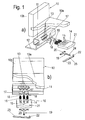
- connection device explained in more detail for connecting a drawer 10 partially shown with a running rail 11 is shown, which is movable along a fixedly attached to a furniture body, not shown, guide rail 12.
- guide rail 12 For the sake of simplified illustration, only the bottom 10a and a side wall 10b of the drawer 10 are shown.
- the running rail 11 is on the inner side facing away from the side wall 10b equipped with three equal height and at the same distance from each other adjusting holes 13.
- a guide plate 14 is fixed to the underside of the bottom 10a of the drawer 10. Because of the clearer explanation of the solution according to the invention, the guide plate 14 above the plane of the connecting pin 17 is shown cut away.
- This guide plate 14 is provided on the running rail 11 facing side with three spaced guides 15 which are formed as blind holes. However, the walls 15 delimiting walls extend arcuately.
- a power storage in the form of a compression spring 16 is used in each guide 15.
- a connecting pin 17 is inserted into each guide 15.
- an unlocking pin 18 which is transverse to the central longitudinal axis of each locking bolt 17 and penetrates through a slot 26, the guide plate 14.
- an unlocking slider 19 is slidably inserted on the guide plate 14.
- This unlocking slide 19 is provided on the side facing the running rail 11 with a Entriegelungssteg 20 which is transverse to the direction of the unlocking slide 19.
- the guide plate 14 On the side facing away from the running rail 11 of the Entriegelungssteg 20 is provided with slots in which the Entriegelungsloche Engage, the guide plate 14 is provided with a bore 21 into which an end-side pin 22 of an unlocking lever 23 is inserted. At this release lever 23 of the release slide 19 is hinged.
- the unlocking slide 19 is provided on the side facing away from the running rail 11 with a bearing pin 24 which engages in a bore 25 of the unlocking lever 23.
- FIG. 1 a shows the above-described connecting device in an oblique perspective and an exploded view, while the FIG. 1b this arrangement shows in a transversely to the extension direction blasting image representation.
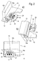
- FIG. 2a shows one of the FIG. 1a corresponding representation, however, the connecting device is shown in the assembled state.
- the Figure 2c shows this connection device in a plan view and the FIG. 2b shows this connection device in a rotated position by 180 °, ie, in a bottom view perspective.
- the distances of the guides 15 and thus the connecting pins 17 are different from the distances between the individual adjustment holes 13, but are in the same plane.
- the distances of the guides 15 are slightly larger, for example by a range of two millimeters, than the distances between the adjusting holes 13
- FIGS. 2a, 2b, 2c show that in the illustrated embodiment, the middle connecting pin 17 is retracted in the associated central adjustment hole 13.
- either the drawer 10 or the running rail 11 can be moved so that one of the outer connecting pin 17 engages in the associated adjusting hole 13. In the starting position, all connecting bolts 17 are retracted.
- the running rail 11 forms the first furniture component and the drawer 10, the second furniture component, which form a structural unit by a respective adjusting hole 13 and a retracted connecting pin 17, wherein the components in operative connection with the connecting pin 17 belonging to the connecting device.
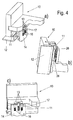
- FIGS. 3a, 3b . 4a, 4b, 4c show a reference to the previously discussed figures identical connection device, however, the adjustment holes 13 are formed as outgoing from the bottom of the bottom 10a of the drawer 10 blind holes.
- the guide plate 14, here again the page lying to the viewer is cut away to the level of the connecting elements, including the compression springs 16 and the connecting pin 17 and the unlocking slide 19 and the release lever 23 are fixed to the running rail 11. Accordingly, the guide plate 14 is parallel and at a distance from the side wall 10b of the drawer 10.
- the guide plate 14 is at a distance from the facing leg of the running rail 11.
- two intermediate webs 26 are attached or integrally formed on this leg of the running rail 11.
- the unlocking slide 19 is located between these webs in particular the Figures 4a, 4b and 4c demonstrate.
- FIG. 3 shows the connecting device in a perspective and an exploded view
- the FIG. 3b shows the connecting device in an exploded side view with a view of the side wall 10b of the drawer 10
- the FIG. 4a shows the connecting device according to the FIG. 3a , but in the assembled state
- the Figure 4c shows the assembled connection device in a side view with a view of the side wall 10b of the drawer 10
- the FIG. 4b shows the connecting device in a bottom view overlooking the bottom 10 a of the drawer 10th
- the in the FIGS. 3a to 4c shown connecting device is a reversal of the in the FIGS. 1a to 2c shown device. Accordingly, in this embodiment, the bottom 10a of the drawer 10, the first furniture component and the running rail 11 with the attached guide plate 14, the second furniture component.
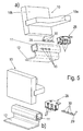
- the FIGS. 5a, 5b . 6a, 6b and 6c show a third embodiment of the assembly according to the invention.
- the FIG. 5a shows these in a perspective and an exploded view with respect to the inner surface of the side wall 10b of the drawer 10 and the FIG. 5b shows this embodiment with a view of the outer surface of the side wall 10b of the drawer 10th Die FIG.
- FIG. 6a shows this connection device in the assembled state in a perspective view of the running rail 11 and the lower side of the bottom 10a of the drawer 10th Die
- FIG. 6b shows this connection device in a side view and the FIG. 6c this connection device in a perspective view overlooking the lower surface of the bottom 10a of the drawer 10th
- FIG. 5a shows the Justierlöcher 13 are also arranged in this embodiment in the track rail 11, but they are designed rectangular in contrast to the previously described embodiments, wherein the distances are again the same.
- spring tongues 27 which are integrally formed on a holder 28 having a mounting plate to set this at the bottom of the bottom 10a of the drawer 10.
- the spacings of the spring tongues 27 also deviate from the distances of the adjusting holes 13 in this embodiment.
- the middle spring tongue 27 is pivoted into the associated adjustment hole 13. Depending on the position of the drawer 10 to the running rail 11 and one of the outer spring tongues 27 can pivot into the associated adjustment hole 13.
- Entriegelungsstab 29 which carries three spaced Entriegelungsnocken 30. It is apparent from the figures that by rotation of the Entriegelungsstabes 29 which is pivoted into an adjustment hole 13 spring tongue 27 is pushed out of the adjustment hole 13, so that the mutual adjustment of the drawer 10 to the running rail 11 can be performed.
- the running rail 11 forms the first furniture component and the drawer 10 with the attached to the bottom 10 a holder 28, the second furniture component. Also in this embodiment, the reversal is possible.
- the invention is not limited to the illustrated embodiments. It is essential that the mutually to be adjusted furniture components 10, 11 can be connected to each other via a connecting device without adjustment screws or similar components must be rotated by a tool and that in a furniture component adjustment holes 13 and in the other furniture component fasteners in the form of connecting pin 17th or spring tongues 27 engage. Furthermore, it is essential that the distances between the adjusting holes 13 and the connecting elements 17, 27 differ from each other.
Landscapes
- Drawers Of Furniture (AREA)
Claims (13)
- Première pièce de meuble et seconde pièce de meuble (10, 11) pouvant être assemblées au moyen d'un dispositif d'assemblage et ajustées l'une par rapport à l'autre, dans lesquelles sont prévus dans la seconde pièce de meuble (11, 10) au moins deux éléments d'assemblage verticaux (17, 27) écartés l'un de l'autre, et dans lesquelles est prévu dans la première pièce de meuble (10, 11) au moins un nombre de trous d'ajustement (13) correspondant au nombre des éléments d'assemblage (17, 27), caractérisées en ce que les écartements des éléments d'assemblage (17, 27) diffèrent des écartements des trous d'ajustement (13) de telle façon qu'un seul élément d'assemblage (17, 27) puisse se mettre en prise dans chaque trou d'ajustement (13) et les éléments d'assemblage (17, 27) et les trous d'ajustement (13) se trouvent dans un plan de translation.
- Dispositif d'assemblage selon la revendication 1, caractérisé en ce que trois trous d'ajustement (13) écartés sont prévus dans la première pièce de meuble (11, 10) et trois éléments d'assemblage (17, 27) écartés dans la seconde pièce de meuble (10, 11).
- Dispositif d'assemblage selon la revendication 1 ou 2, caractérisé en ce que les écartements entre les éléments d'assemblage (17, 27) sont plus grands ou plus petits que les écartements entre les trous d'ajustement (13).
- Dispositif d'assemblage selon une ou plusieurs des revendications précédentes, caractérisé en ce que les éléments d'assemblage sont conçus comme des boulons d'assemblage (17) déplaçables dans le sens longitudinal des trous d'ajustement (13).
- Dispositif d'assemblage selon la revendication 3, caractérisé en ce que chaque boulon d'assemblage (17) est contraint par un accumulateur de force, de préférence formé par un ressort de compression (16).
- Dispositif d'assemblage selon la revendication 4 ou 5, caractérisé en ce que chaque boulon d'assemblage (17) est inséré dans un guide (15) d'une plaque de guidage (14) fixée à la première ou seconde pièce de meuble (10, 11).
- Dispositif d'assemblage selon une ou plusieurs des revendications précédentes, caractérisé en ce que les boulons d'assemblage (17) sont munis dans les parties d'extrémité tournées vers les accumulateurs de force (16) d'une goupille de déverrouillage (18) perpendiculaire à l'axe longitudinal médian du boulon d'assemblage (17) correspondant.
- Dispositif d'assemblage selon la revendication 7, caractérisé en ce que les canaux de guidage (15) sont ouverts ou présentent des fentes au moins du côté tourné vers les goupilles de déverrouillage (18).
- Dispositif d'assemblage selon la revendication 8, caractérisé en ce que la plaque de guidage (14) est assemblée à demeure à la première ou seconde pièce de meuble et en ce qu'est disposé du côté tourné vers les goupilles de déverrouillage une coulisse de déverrouillage (19) pouvant coulisser dans le sens longitudinal des boulons de déverrouillage (17), qui est en liaison active avec les goupilles de déverrouillage (18).
- Dispositif d'assemblage selon la revendication 9, caractérisé en ce que la coulisse de déverrouillage (19) présente une barrette de déverrouillage (20) munie d'ouvertures dans lesquelles les goupilles de déverrouillage (18) se mettent en prise.
- Dispositif d'assemblage selon une ou plusieurs des revendications précédentes, caractérisé en ce qu'un levier de déverrouillage (23) sur lequel est articulée la coulisse de déverrouillage (19) est supporté de façon pivotante sur la plaque de guidage (14).
- Dispositif d'assemblage selon la revendication 1, caractérisé en ce que les éléments d'assemblage sont conformés comme des languettes-ressorts (27) qui sont posées ou formées sur une fixation (28) qui est posée, formée ou détachée sur la première pièce de meuble (11 ou 10).
- Dispositif d'assemblage selon la revendication 12, caractérisé en ce qu'une barre de déverrouillage (29) munie de cames de déverrouillage (30) est supportée avec possibilité de rotation dans la fixation (28).
Applications Claiming Priority (1)
| Application Number | Priority Date | Filing Date | Title |
|---|---|---|---|
| DE202009006443U DE202009006443U1 (de) | 2009-05-02 | 2009-05-02 | Verbindungsvorrichtung |
Publications (2)
| Publication Number | Publication Date |
|---|---|
| EP2245963A1 EP2245963A1 (fr) | 2010-11-03 |
| EP2245963B1 true EP2245963B1 (fr) | 2012-08-22 |
Family
ID=42338282
Family Applications (1)
| Application Number | Title | Priority Date | Filing Date |
|---|---|---|---|
| EP10161587A Not-in-force EP2245963B1 (fr) | 2009-05-02 | 2010-04-30 | Élément constitué d'une première et seconde pièce de meuble étant connectées et ajustables par un dispositif de connexion |
Country Status (4)
| Country | Link |
|---|---|
| US (1) | US20100278588A1 (fr) |
| EP (1) | EP2245963B1 (fr) |
| DE (1) | DE202009006443U1 (fr) |
| ES (1) | ES2393858T3 (fr) |
Families Citing this family (8)
| Publication number | Priority date | Publication date | Assignee | Title |
|---|---|---|---|---|
| US20120021400A1 (en) * | 2010-07-23 | 2012-01-26 | Artapower International Group Limited | Multi-direction board and accessory interlock system |
| AT13009U1 (de) * | 2011-04-19 | 2013-04-15 | Blum Gmbh Julius | Schubladensystem mit zwei an einem möbelkorpus zu befestigenden schubladenausziehführungen und mit einer schublade |
| AT511081B1 (de) | 2011-05-05 | 2012-09-15 | Blum Gmbh Julius | Anordnung mit einer schublade und mit einer schubladenausziehführung |
| ITMI20111454A1 (it) * | 2011-07-29 | 2013-01-30 | Salice Arturo Spa | Dispositivo di aggancio per il fissaggio di un cassetto ad una guida |
| BR302012003198S1 (pt) | 2012-01-02 | 2014-10-14 | Brita Gmbh | Configuração aplicada a garrafa de bebida |
| CN104019347A (zh) * | 2014-05-16 | 2014-09-03 | 李理 | 一种杆件安装卡座 |
| AT518232B1 (de) * | 2016-01-19 | 2018-02-15 | Blum Gmbh Julius | Schubladenanordnung |
| DE102016207417A1 (de) | 2016-04-29 | 2017-11-02 | Siemens Healthcare Gmbh | Schienenführung mit einer Feststelleinheit, Patiententisch mit einer Schienenführung für Zubehör und Verfahren zum Betrieb einer Schienenführung |
Family Cites Families (19)
| Publication number | Priority date | Publication date | Assignee | Title |
|---|---|---|---|---|
| US1806642A (en) * | 1931-05-26 | Enoch ohnstrand | ||
| US3381927A (en) * | 1966-09-27 | 1968-05-07 | Universal Oil Prod Co | Track attachment means for seats and the like |
| SE434683B (sv) * | 1982-02-25 | 1984-08-06 | Lundblad Leif | Anordning for utmatning av verdepapper |
| US4712759A (en) * | 1985-05-11 | 1987-12-15 | Honda Giken Kogyo Kabushiki Kaisha | Lock structure for seat slide device |
| DE4400232C2 (de) * | 1994-01-05 | 2002-09-12 | Hammerstein Gmbh C Rob | Stufenfreie Feststellvorrichtung für einen einstellbaren Fahrzeugsitz |
| US5741000A (en) * | 1995-09-13 | 1998-04-21 | Atoma International, Inc. | Vehicle seat track assembly |
| DE19735030A1 (de) * | 1997-08-13 | 1999-02-25 | Keiper Gmbh & Co | Verriegelungsvorrichtung für Fahrzeugsitze, insbesondere Kraftfahrzeugsitze |
| DE19825099B4 (de) * | 1998-06-05 | 2008-01-10 | C. Rob. Hammerstein Gmbh & Co. Kg | Längsführung eines Fahrzeugsitzes mit Arretiervorrichtung |
| US6354553B1 (en) * | 2000-03-01 | 2002-03-12 | Dura Global Technologies, Inc. | Seat track assembly with positive lock mechanism |
| US20030006355A1 (en) * | 2001-07-09 | 2003-01-09 | Horsfield Keith C. | Seat track assembly with locking mechanism |
| DE10201111A1 (de) * | 2002-01-09 | 2003-07-10 | Moll System & Funktionsmoebel Gmbh | Teleskopeinrichtung, insbesondere für den Möbelbau |
| US6637712B1 (en) * | 2002-05-17 | 2003-10-28 | Dura Global Technologies, Inc. | Automotive seat track lock mechanism with positive engagement |
| DE20314237U1 (de) * | 2003-09-09 | 2005-01-13 | Brose Fahrzeugteile Gmbh & Co. Kg, Coburg | Memory-Einrichtung für eine Schienenlängsführung eines Kraftfahrzeuges |
| KR100610431B1 (ko) * | 2004-10-02 | 2006-08-09 | 기아자동차주식회사 | 자동차용 시트 슬라이드 장치 |
| CN100579817C (zh) * | 2004-11-12 | 2010-01-13 | 约翰逊控制技术公司 | 车辆座椅导轨 |
| CN1955041B (zh) * | 2005-10-27 | 2010-05-19 | C.劳勃汉默斯坦两合有限公司 | 带有两对导轨的机动车辆座位的纵向调节机构的保持装置 |
| DE202007014954U1 (de) * | 2007-10-31 | 2008-12-18 | Grass Gmbh | Vorrichtung zur Anbringung einer Führungseinheit sowie Möbelteil und Möbel mit einer solchen Vorrichtung |
| JP5275747B2 (ja) * | 2008-10-23 | 2013-08-28 | デルタ工業株式会社 | シートのスライドロック装置 |
| US8382057B2 (en) * | 2010-03-31 | 2013-02-26 | Crh North America, Inc. | Low profile seat track system |
-
2009
- 2009-05-02 DE DE202009006443U patent/DE202009006443U1/de not_active Expired - Lifetime
-
2010
- 2010-04-30 EP EP10161587A patent/EP2245963B1/fr not_active Not-in-force
- 2010-04-30 ES ES10161587T patent/ES2393858T3/es active Active
- 2010-04-30 US US12/771,843 patent/US20100278588A1/en not_active Abandoned
Also Published As
| Publication number | Publication date |
|---|---|
| DE202009006443U1 (de) | 2010-09-23 |
| US20100278588A1 (en) | 2010-11-04 |
| ES2393858T3 (es) | 2012-12-28 |
| EP2245963A1 (fr) | 2010-11-03 |
Similar Documents
| Publication | Publication Date | Title |
|---|---|---|
| DE69715980T2 (de) | Verriegelungssystem mit Stangenverschluss für Schubladen | |
| EP2245963A1 (fr) | Dispositif de connexion | |
| DE3038880C2 (de) | Vorrichtung zur stufenweisen Abstandsverstellung von zwei Stuhlteilen | |
| EP0384153A2 (fr) | Chaîne porteuse pour lignes de transport d'énergie | |
| EP2851496A1 (fr) | Dispositif de montage réglable pour un élément coulissant et dispositif coulissant | |
| EP2211004A1 (fr) | Dispositif de verrouillage | |
| DE102011008172A1 (de) | Armlehne, insbesondere für einen Bürostuhl | |
| WO2014183867A1 (fr) | Outil de moulage par injection de pièces en matière plastique | |
| EP2916686B1 (fr) | Élément de guidage coulissant et système de fixation de plateau de table pour la fixation coulissante d'un plateau de table | |
| DE102008020986A1 (de) | Vorrichtung mit einem Unterteil und einer Rückholfeder zur drehbaren Lagerung eines Ausstattungsteils, insbesondere eines Türdrückers | |
| WO2013156287A1 (fr) | Guidage linéaire à rattrapage de jeu | |
| EP3945936B1 (fr) | Dispositif de chargement ou d'éjection | |
| EP0169315A2 (fr) | Elément de fixation de ski en particulier mâchoire avant | |
| DE102005028573A1 (de) | Befestigungsanordnung für Möbelteile, insbesondere Tischmöbelteile | |
| WO1995030974A1 (fr) | Serrure actionnee par des pieces de monnaie | |
| DE102021108249A1 (de) | Koppelelement, Schließsystem und Möbel | |
| DE202013004939U1 (de) | Vorrichtung zur Positionierung und Fixierung eines beweglichen Möbelteils | |
| DE202012103425U1 (de) | Bettlattenrost | |
| DE29904029U1 (de) | Halter für Stiftschlüssel | |
| EP4124709B1 (fr) | Profilé de guidage pour un verrou de tiroir, verrou de tiroir, meuble et procédé de montage d'un profilé de guidage | |
| WO2015078765A1 (fr) | Organe d'écartement pour dispositif de guidage par glissement et colonne de levage | |
| DE9104766U1 (de) | Antipaniktürschloß | |
| EP0199270A2 (fr) | Dispositif pour maintenir une porte ou une fenêtre entrouverte dans au moins une position | |
| EP1794053A1 (fr) | Dispositif de fixation d'un objet sur un rail | |
| DE4239199C2 (de) | Klemmverbindung |
Legal Events
| Date | Code | Title | Description |
|---|---|---|---|
| PUAI | Public reference made under article 153(3) epc to a published international application that has entered the european phase |
Free format text: ORIGINAL CODE: 0009012 |
|
| AK | Designated contracting states |
Kind code of ref document: A1 Designated state(s): AT BE BG CH CY CZ DE DK EE ES FI FR GB GR HR HU IE IS IT LI LT LU LV MC MK MT NL NO PL PT RO SE SI SK SM TR |
|
| AX | Request for extension of the european patent |
Extension state: AL BA ME RS |
|
| 17P | Request for examination filed |
Effective date: 20110426 |
|
| GRAP | Despatch of communication of intention to grant a patent |
Free format text: ORIGINAL CODE: EPIDOSNIGR1 |
|
| RTI1 | Title (correction) |
Free format text: CONSTRUCTIONAL UNIT FORMED BY A FIRST AND SECOND PIECE OF FURNITURE BEING ADJUSTABLY CONNECTABLE BY A CONNECTING DEVICE |
|
| GRAS | Grant fee paid |
Free format text: ORIGINAL CODE: EPIDOSNIGR3 |
|
| GRAA | (expected) grant |
Free format text: ORIGINAL CODE: 0009210 |
|
| AK | Designated contracting states |
Kind code of ref document: B1 Designated state(s): AT BE BG CH CY CZ DE DK EE ES FI FR GB GR HR HU IE IS IT LI LT LU LV MC MK MT NL NO PL PT RO SE SI SK SM TR |
|
| REG | Reference to a national code |
Ref country code: GB Ref legal event code: FG4D Free format text: NOT ENGLISH |
|
| REG | Reference to a national code |
Ref country code: CH Ref legal event code: EP |
|
| REG | Reference to a national code |
Ref country code: IE Ref legal event code: FG4D Free format text: LANGUAGE OF EP DOCUMENT: GERMAN |
|
| REG | Reference to a national code |
Ref country code: AT Ref legal event code: REF Ref document number: 571432 Country of ref document: AT Kind code of ref document: T Effective date: 20120915 |
|
| REG | Reference to a national code |
Ref country code: DE Ref legal event code: R096 Ref document number: 502010001128 Country of ref document: DE Effective date: 20121018 |
|
| REG | Reference to a national code |
Ref country code: NL Ref legal event code: VDEP Effective date: 20120822 |
|
| REG | Reference to a national code |
Ref country code: ES Ref legal event code: FG2A Ref document number: 2393858 Country of ref document: ES Kind code of ref document: T3 Effective date: 20121228 |
|
| REG | Reference to a national code |
Ref country code: LT Ref legal event code: MG4D Effective date: 20120822 |
|
| PG25 | Lapsed in a contracting state [announced via postgrant information from national office to epo] |
Ref country code: IS Free format text: LAPSE BECAUSE OF FAILURE TO SUBMIT A TRANSLATION OF THE DESCRIPTION OR TO PAY THE FEE WITHIN THE PRESCRIBED TIME-LIMIT Effective date: 20121222 Ref country code: NO Free format text: LAPSE BECAUSE OF FAILURE TO SUBMIT A TRANSLATION OF THE DESCRIPTION OR TO PAY THE FEE WITHIN THE PRESCRIBED TIME-LIMIT Effective date: 20121122 Ref country code: FI Free format text: LAPSE BECAUSE OF FAILURE TO SUBMIT A TRANSLATION OF THE DESCRIPTION OR TO PAY THE FEE WITHIN THE PRESCRIBED TIME-LIMIT Effective date: 20120822 Ref country code: HR Free format text: LAPSE BECAUSE OF FAILURE TO SUBMIT A TRANSLATION OF THE DESCRIPTION OR TO PAY THE FEE WITHIN THE PRESCRIBED TIME-LIMIT Effective date: 20120822 Ref country code: LT Free format text: LAPSE BECAUSE OF FAILURE TO SUBMIT A TRANSLATION OF THE DESCRIPTION OR TO PAY THE FEE WITHIN THE PRESCRIBED TIME-LIMIT Effective date: 20120822 |
|
| PG25 | Lapsed in a contracting state [announced via postgrant information from national office to epo] |
Ref country code: SI Free format text: LAPSE BECAUSE OF FAILURE TO SUBMIT A TRANSLATION OF THE DESCRIPTION OR TO PAY THE FEE WITHIN THE PRESCRIBED TIME-LIMIT Effective date: 20120822 Ref country code: LV Free format text: LAPSE BECAUSE OF FAILURE TO SUBMIT A TRANSLATION OF THE DESCRIPTION OR TO PAY THE FEE WITHIN THE PRESCRIBED TIME-LIMIT Effective date: 20120822 Ref country code: SE Free format text: LAPSE BECAUSE OF FAILURE TO SUBMIT A TRANSLATION OF THE DESCRIPTION OR TO PAY THE FEE WITHIN THE PRESCRIBED TIME-LIMIT Effective date: 20120822 Ref country code: PT Free format text: LAPSE BECAUSE OF FAILURE TO SUBMIT A TRANSLATION OF THE DESCRIPTION OR TO PAY THE FEE WITHIN THE PRESCRIBED TIME-LIMIT Effective date: 20121224 Ref country code: GR Free format text: LAPSE BECAUSE OF FAILURE TO SUBMIT A TRANSLATION OF THE DESCRIPTION OR TO PAY THE FEE WITHIN THE PRESCRIBED TIME-LIMIT Effective date: 20121123 |
|
| PG25 | Lapsed in a contracting state [announced via postgrant information from national office to epo] |
Ref country code: NL Free format text: LAPSE BECAUSE OF FAILURE TO SUBMIT A TRANSLATION OF THE DESCRIPTION OR TO PAY THE FEE WITHIN THE PRESCRIBED TIME-LIMIT Effective date: 20120822 |
|
| PG25 | Lapsed in a contracting state [announced via postgrant information from national office to epo] |
Ref country code: DK Free format text: LAPSE BECAUSE OF FAILURE TO SUBMIT A TRANSLATION OF THE DESCRIPTION OR TO PAY THE FEE WITHIN THE PRESCRIBED TIME-LIMIT Effective date: 20120822 Ref country code: EE Free format text: LAPSE BECAUSE OF FAILURE TO SUBMIT A TRANSLATION OF THE DESCRIPTION OR TO PAY THE FEE WITHIN THE PRESCRIBED TIME-LIMIT Effective date: 20120822 Ref country code: RO Free format text: LAPSE BECAUSE OF FAILURE TO SUBMIT A TRANSLATION OF THE DESCRIPTION OR TO PAY THE FEE WITHIN THE PRESCRIBED TIME-LIMIT Effective date: 20120822 Ref country code: CZ Free format text: LAPSE BECAUSE OF FAILURE TO SUBMIT A TRANSLATION OF THE DESCRIPTION OR TO PAY THE FEE WITHIN THE PRESCRIBED TIME-LIMIT Effective date: 20120822 |
|
| PG25 | Lapsed in a contracting state [announced via postgrant information from national office to epo] |
Ref country code: SK Free format text: LAPSE BECAUSE OF FAILURE TO SUBMIT A TRANSLATION OF THE DESCRIPTION OR TO PAY THE FEE WITHIN THE PRESCRIBED TIME-LIMIT Effective date: 20120822 Ref country code: PL Free format text: LAPSE BECAUSE OF FAILURE TO SUBMIT A TRANSLATION OF THE DESCRIPTION OR TO PAY THE FEE WITHIN THE PRESCRIBED TIME-LIMIT Effective date: 20120822 |
|
| PLBE | No opposition filed within time limit |
Free format text: ORIGINAL CODE: 0009261 |
|
| STAA | Information on the status of an ep patent application or granted ep patent |
Free format text: STATUS: NO OPPOSITION FILED WITHIN TIME LIMIT |
|
| 26N | No opposition filed |
Effective date: 20130523 |
|
| PG25 | Lapsed in a contracting state [announced via postgrant information from national office to epo] |
Ref country code: BG Free format text: LAPSE BECAUSE OF FAILURE TO SUBMIT A TRANSLATION OF THE DESCRIPTION OR TO PAY THE FEE WITHIN THE PRESCRIBED TIME-LIMIT Effective date: 20121122 |
|
| REG | Reference to a national code |
Ref country code: DE Ref legal event code: R097 Ref document number: 502010001128 Country of ref document: DE Effective date: 20130523 |
|
| BERE | Be: lapsed |
Owner name: PAUL HETTICH G.M.B.H. & CO. KG Effective date: 20130430 |
|
| PG25 | Lapsed in a contracting state [announced via postgrant information from national office to epo] |
Ref country code: CY Free format text: LAPSE BECAUSE OF FAILURE TO SUBMIT A TRANSLATION OF THE DESCRIPTION OR TO PAY THE FEE WITHIN THE PRESCRIBED TIME-LIMIT Effective date: 20120822 Ref country code: MC Free format text: LAPSE BECAUSE OF FAILURE TO SUBMIT A TRANSLATION OF THE DESCRIPTION OR TO PAY THE FEE WITHIN THE PRESCRIBED TIME-LIMIT Effective date: 20120822 |
|
| REG | Reference to a national code |
Ref country code: IE Ref legal event code: MM4A |
|
| PG25 | Lapsed in a contracting state [announced via postgrant information from national office to epo] |
Ref country code: BE Free format text: LAPSE BECAUSE OF NON-PAYMENT OF DUE FEES Effective date: 20130430 |
|
| REG | Reference to a national code |
Ref country code: FR Ref legal event code: ST Effective date: 20131231 |
|
| PG25 | Lapsed in a contracting state [announced via postgrant information from national office to epo] |
Ref country code: FR Free format text: LAPSE BECAUSE OF NON-PAYMENT OF DUE FEES Effective date: 20130430 |
|
| PG25 | Lapsed in a contracting state [announced via postgrant information from national office to epo] |
Ref country code: IE Free format text: LAPSE BECAUSE OF NON-PAYMENT OF DUE FEES Effective date: 20130430 |
|
| PGFP | Annual fee paid to national office [announced via postgrant information from national office to epo] |
Ref country code: IT Payment date: 20140428 Year of fee payment: 5 Ref country code: TR Payment date: 20140424 Year of fee payment: 5 Ref country code: ES Payment date: 20140417 Year of fee payment: 5 |
|
| REG | Reference to a national code |
Ref country code: CH Ref legal event code: PL |
|
| GBPC | Gb: european patent ceased through non-payment of renewal fee |
Effective date: 20140430 |
|
| PG25 | Lapsed in a contracting state [announced via postgrant information from national office to epo] |
Ref country code: LI Free format text: LAPSE BECAUSE OF NON-PAYMENT OF DUE FEES Effective date: 20140430 Ref country code: GB Free format text: LAPSE BECAUSE OF NON-PAYMENT OF DUE FEES Effective date: 20140430 Ref country code: CH Free format text: LAPSE BECAUSE OF NON-PAYMENT OF DUE FEES Effective date: 20140430 |
|
| PG25 | Lapsed in a contracting state [announced via postgrant information from national office to epo] |
Ref country code: MT Free format text: LAPSE BECAUSE OF FAILURE TO SUBMIT A TRANSLATION OF THE DESCRIPTION OR TO PAY THE FEE WITHIN THE PRESCRIBED TIME-LIMIT Effective date: 20120822 |
|
| PG25 | Lapsed in a contracting state [announced via postgrant information from national office to epo] |
Ref country code: SM Free format text: LAPSE BECAUSE OF FAILURE TO SUBMIT A TRANSLATION OF THE DESCRIPTION OR TO PAY THE FEE WITHIN THE PRESCRIBED TIME-LIMIT Effective date: 20120822 |
|
| PG25 | Lapsed in a contracting state [announced via postgrant information from national office to epo] |
Ref country code: HU Free format text: LAPSE BECAUSE OF FAILURE TO SUBMIT A TRANSLATION OF THE DESCRIPTION OR TO PAY THE FEE WITHIN THE PRESCRIBED TIME-LIMIT; INVALID AB INITIO Effective date: 20100430 Ref country code: MK Free format text: LAPSE BECAUSE OF FAILURE TO SUBMIT A TRANSLATION OF THE DESCRIPTION OR TO PAY THE FEE WITHIN THE PRESCRIBED TIME-LIMIT Effective date: 20120822 Ref country code: LU Free format text: LAPSE BECAUSE OF NON-PAYMENT OF DUE FEES Effective date: 20130430 |
|
| PG25 | Lapsed in a contracting state [announced via postgrant information from national office to epo] |
Ref country code: IT Free format text: LAPSE BECAUSE OF NON-PAYMENT OF DUE FEES Effective date: 20150430 |
|
| REG | Reference to a national code |
Ref country code: ES Ref legal event code: FD2A Effective date: 20160526 |
|
| REG | Reference to a national code |
Ref country code: AT Ref legal event code: MM01 Ref document number: 571432 Country of ref document: AT Kind code of ref document: T Effective date: 20150430 |
|
| PG25 | Lapsed in a contracting state [announced via postgrant information from national office to epo] |
Ref country code: ES Free format text: LAPSE BECAUSE OF NON-PAYMENT OF DUE FEES Effective date: 20150501 |
|
| PG25 | Lapsed in a contracting state [announced via postgrant information from national office to epo] |
Ref country code: AT Free format text: LAPSE BECAUSE OF NON-PAYMENT OF DUE FEES Effective date: 20150430 |
|
| REG | Reference to a national code |
Ref country code: DE Ref legal event code: R079 Ref document number: 502010001128 Country of ref document: DE Free format text: PREVIOUS MAIN CLASS: A47B0088040000 Ipc: A47B0088400000 |
|
| PG25 | Lapsed in a contracting state [announced via postgrant information from national office to epo] |
Ref country code: TR Free format text: LAPSE BECAUSE OF NON-PAYMENT OF DUE FEES Effective date: 20150430 |
|
| REG | Reference to a national code |
Ref country code: DE Ref legal event code: R084 Ref document number: 502010001128 Country of ref document: DE |
|
| P01 | Opt-out of the competence of the unified patent court (upc) registered |
Effective date: 20230415 |
|
| PGFP | Annual fee paid to national office [announced via postgrant information from national office to epo] |
Ref country code: DE Payment date: 20230418 Year of fee payment: 14 |
|
| REG | Reference to a national code |
Ref country code: DE Ref legal event code: R119 Ref document number: 502010001128 Country of ref document: DE |
|
| PG25 | Lapsed in a contracting state [announced via postgrant information from national office to epo] |
Ref country code: DE Free format text: LAPSE BECAUSE OF NON-PAYMENT OF DUE FEES Effective date: 20241105 |
|
| PG25 | Lapsed in a contracting state [announced via postgrant information from national office to epo] |
Ref country code: DE Free format text: LAPSE BECAUSE OF NON-PAYMENT OF DUE FEES Effective date: 20241105 |