EP2245984B1 - Biologische Informationsdetektionsvorrichtung - Google Patents
Biologische Informationsdetektionsvorrichtung Download PDFInfo
- Publication number
- EP2245984B1 EP2245984B1 EP10005860.1A EP10005860A EP2245984B1 EP 2245984 B1 EP2245984 B1 EP 2245984B1 EP 10005860 A EP10005860 A EP 10005860A EP 2245984 B1 EP2245984 B1 EP 2245984B1
- Authority
- EP
- European Patent Office
- Prior art keywords
- arm
- biologic information
- cuff
- detecting apparatus
- information detecting
- Prior art date
- Legal status (The legal status is an assumption and is not a legal conclusion. Google has not performed a legal analysis and makes no representation as to the accuracy of the status listed.)
- Expired - Lifetime
Links
Images









Classifications
-
- A—HUMAN NECESSITIES
- A61—MEDICAL OR VETERINARY SCIENCE; HYGIENE
- A61B—DIAGNOSIS; SURGERY; IDENTIFICATION
- A61B5/00—Measuring for diagnostic purposes; Identification of persons
- A61B5/02—Detecting, measuring or recording for evaluating the cardiovascular system, e.g. pulse, heart rate, blood pressure or blood flow
- A61B5/024—Measuring pulse rate or heart rate
- A61B5/0245—Measuring pulse rate or heart rate by using sensing means generating electric signals, i.e. ECG signals
-
- A—HUMAN NECESSITIES
- A61—MEDICAL OR VETERINARY SCIENCE; HYGIENE
- A61B—DIAGNOSIS; SURGERY; IDENTIFICATION
- A61B5/00—Measuring for diagnostic purposes; Identification of persons
- A61B5/68—Arrangements of detecting, measuring or recording means, e.g. sensors, in relation to patient
- A61B5/6801—Arrangements of detecting, measuring or recording means, e.g. sensors, in relation to patient specially adapted to be attached to or worn on the body surface
- A61B5/6813—Specially adapted to be attached to a specific body part
- A61B5/6814—Head
- A61B5/6815—Ear
- A61B5/6816—Ear lobe
-
- A—HUMAN NECESSITIES
- A61—MEDICAL OR VETERINARY SCIENCE; HYGIENE
- A61B—DIAGNOSIS; SURGERY; IDENTIFICATION
- A61B5/00—Measuring for diagnostic purposes; Identification of persons
- A61B5/02—Detecting, measuring or recording for evaluating the cardiovascular system, e.g. pulse, heart rate, blood pressure or blood flow
-
- A—HUMAN NECESSITIES
- A61—MEDICAL OR VETERINARY SCIENCE; HYGIENE
- A61B—DIAGNOSIS; SURGERY; IDENTIFICATION
- A61B5/00—Measuring for diagnostic purposes; Identification of persons
- A61B5/02—Detecting, measuring or recording for evaluating the cardiovascular system, e.g. pulse, heart rate, blood pressure or blood flow
- A61B5/021—Measuring pressure in heart or blood vessels
-
- A—HUMAN NECESSITIES
- A61—MEDICAL OR VETERINARY SCIENCE; HYGIENE
- A61B—DIAGNOSIS; SURGERY; IDENTIFICATION
- A61B5/00—Measuring for diagnostic purposes; Identification of persons
- A61B5/68—Arrangements of detecting, measuring or recording means, e.g. sensors, in relation to patient
- A61B5/6801—Arrangements of detecting, measuring or recording means, e.g. sensors, in relation to patient specially adapted to be attached to or worn on the body surface
- A61B5/6813—Specially adapted to be attached to a specific body part
- A61B5/6814—Head
- A61B5/6815—Ear
- A61B5/6817—Ear canal
-
- A—HUMAN NECESSITIES
- A61—MEDICAL OR VETERINARY SCIENCE; HYGIENE
- A61B—DIAGNOSIS; SURGERY; IDENTIFICATION
- A61B5/00—Measuring for diagnostic purposes; Identification of persons
- A61B5/02—Detecting, measuring or recording for evaluating the cardiovascular system, e.g. pulse, heart rate, blood pressure or blood flow
- A61B5/021—Measuring pressure in heart or blood vessels
- A61B5/022—Measuring pressure in heart or blood vessels by applying pressure to close blood vessels, e.g. against the skin; Ophthalmodynamometers
- A61B5/02233—Occluders specially adapted therefor
- A61B5/02241—Occluders specially adapted therefor of small dimensions, e.g. adapted to fingers
-
- Y—GENERAL TAGGING OF NEW TECHNOLOGICAL DEVELOPMENTS; GENERAL TAGGING OF CROSS-SECTIONAL TECHNOLOGIES SPANNING OVER SEVERAL SECTIONS OF THE IPC; TECHNICAL SUBJECTS COVERED BY FORMER USPC CROSS-REFERENCE ART COLLECTIONS [XRACs] AND DIGESTS
- Y10—TECHNICAL SUBJECTS COVERED BY FORMER USPC
- Y10T—TECHNICAL SUBJECTS COVERED BY FORMER US CLASSIFICATION
- Y10T24/00—Buckles, buttons, clasps, etc.
- Y10T24/44—Clasp, clip, support-clamp, or required component thereof
- Y10T24/44291—Clasp, clip, support-clamp, or required component thereof including pivoted gripping member
- Y10T24/44376—Spring or resiliently biased about pivot
- Y10T24/44385—Distinct spring
- Y10T24/44427—Distinct spring with position locking-means for gripping members
Definitions
- the present invention relates to a biologic information detecting apparatus for according to the preamble of claim 1 detecting biologic information from a part of a living body such as auricle of a human body.
- Patent Document 1 discloses, as a method of detecting a pulse wave of an artery or a blood flow, a method of emitting light from a light emitting element to a living body, receiving the light scattered by an artery in the living body or a blood cell in an artery by a light receiving element, and detecting a pulse wave or a blood flow from the scattered light. According to the method, pulsation, pulse wave, heart beat, body temperature, arterial oxygen saturation, blood pressure, and the like can be calculated from a light reception amount of scattered light of infrared light or visible light emitted into a living body.
- an emergency information device having radio communication means and including arterial oxygen saturation sensor, a body temperature sensor, a heart beat sensor, and a pulse wave sensor (refer to, for example, Patent Document 2).
- a blood pressure measuring apparatus using a pulsation waveform of a blood vessel is accepted as one of dominant blood pressure measuring methods besides a blood pressure measuring apparatus (refer to, for example, Non-Patent Document 1) according to a cuff oscillometric method, a volume compensating method, or the like as another method.
- US 4 029 083 A1 shows a probe for an audiometric device that is inserted into an auditory canal.
- the hourglass shaped probe tip is inflated to seal off the probe from the ambient atmosphere.
- US 2003/0036690 A1 shows an inflatable cuff having to semicylindrical sections for measuring blood pressure that is clamped around a finger of a patient.
- the present invention has been achieved to solve the problems and an object of the invention is to provide an easy-to-wear biologic information detecting apparatus for stably detecting biologic information.
- a biologic information detecting apparatus has the features of claim 1.
- the senor is a cuff for applying pressure to a living body and detecting pressure from the living body.
- a pressure pulse wave from the living body can be detected.
- the biologic information detecting apparatus further includes a cuff for pressing a living body, which is attached to the other end of at least one of the pair of arms and attached on the facing sides of the pair of arms, and the sensor may be provided in the cuff.
- biologic information in a living body part pressed by the cuff can be obtained.
- the size of the biologic information detecting apparatus can be reduced.
- the interval between the other ends of the pair of arms can be adjusted by the distance varying mechanism provided for the spindle. By reducing the pressure in the cuff, the cause of error in measurement due to pressurization can be eliminated.
- the cuff is detachable from an arm to which the cuff is attached.
- the interval between the other ends of the pair of arms can be adjusted by the distance varying mechanism provided for the spindle, and replacement of a dirty or worn cuff and sanitary management is facilitated.
- the pair of arms sandwiches a projecting part of an auricle in a human body by an arm disposed on one of side face sides of the projecting part of the auricle in the human body and an arm disposed on the other side face side of the projecting part of the auricle in the human body.
- the biologic information detecting apparatus By sandwiching the projecting part of an auricle by the pair of arms, the biologic information detecting apparatus can be attached to the auricle.
- the pair of arms sandwiches a tragus as a projecting part of an auricle in the human body by an arm disposed on one of side face sides of the tragus as the projecting part of the auricle in the human body and an arm disposed on the other side face side of the tragus as the projecting part of the auricle in the human body.
- the biologic information detecting apparatus can be attached to the auricle.
- the biologic information detecting apparatus is characterized by further including an ear attachment that is placed around the base of an auricle in a human body.
- the biologic information detecting apparatus can be stably attached to an auricle.
- the biologic information detecting apparatus is characterized by further comprising: a cushion provided on an auricle side of an arm disposed on the auricle side in the pair of arms; a magnet provided for at least one of the arm provided with the cushion and the ear attachment; and a magnet or a magnetic member provided for the other one of the arm and the ear attachment.
- the biologic information detecting apparatus can be worn for long time. Since the ear attachment and the cushion attract each other because of the magnetic forces, noise caused by body movement can be reduced.
- the biologic information detecting apparatus is characterized by further including: a bridge connecting the pair of arms attached to one of right and left auricles of a human body and the other auricle to which the pair of arms is not attached; and a power supply unit disposed in some midpoint of the bridge and driving the sensor.
- the biologic information detecting apparatus can be stably attached to the auricle.
- the power supply unit separately from the arm, the weight of the arm can be reduced.
- the biologic information detecting apparatus is characterized by further including: an ear attachment which is hung from the base of an auricle of a human body; and a power supply unit disposed in the ear attachment.
- the biologic information detecting apparatus can be stably attached to an auricle.
- the power supply unit By disposing the power supply unit in the ear attachment, the load on the arm is lessened, and noise caused by vibration of a wire can be reduced.
- the biologic information detecting apparatus of the present invention is easy to wear and can stably detect biologic information.
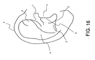
- the inside of a tragus is the side of a cavity of the concha 8 of a tragus 1 in FIG. 16 .
- the outside of a tragus is the side opposite to the cavity of the concha 8 in FIG. 16 .
- a biologic information detecting apparatus of a first embodiment not belonging to the invention has a pair of arms that face each other, a spindle connecting the pair of arms at one end of each of the pair of arms, a distance varying mechanism provided for the spindle and adjusting the interval of the other ends of the pair of arms, a sensor for detecting biometric information, attached to the other end of at least one of the pair of arms and attached on the facing sides of the pair of arms, and an extensible member for shortening the interval between the other ends of the pair of arms.
- the biologic information detecting apparatus may further include a rotating mechanism for rotating at least one of the pair of arms around the spindle as a center axis.
- FIG. 1(A) is a front view showing a configuration example of a biologic information detecting apparatus
- FIG. 1(B) is a plan view showing a configuration example of the above biologic information detecting apparatus.
- the biometric information detecting apparatus shown in FIGS. 1(A) and 1(B) has a distance varying mechanism 40 for adjusting the interval between other ends facing each other of a first arm 31 and a second arm 32, for example, in a portion in which the first and second arms 31 and 32 are connected to a spindle 35.
- the distance varying mechanism 40 has the function of adjusting the interval between facing surfaces of the first and second arms 31 and 32 by changing the angle formed between the spindle 35 and the first arm 35, thereby changing an angle ⁇ shown in FIG. 1(A) .
- a mechanism of adjusting the angle between the spindle 35 and the first arm 31 by a screw a mechanism using both friction and screwing, or the like may be used.
- a mechanism of adjusting the interval between the facing other ends of the first and second arms 31 and 32 a mechanism of adjusting the length of the spindle 35 may be used.
- the biologic information detecting apparatus shown in FIG. 1(A) has, in its part in which the first arm 31 and the spindle 35 are connected to each other, a rotating mechanism 41 which is obtained by breaking the tip of the spindle 35 of the first arm 31 and moves the spindle 35 in the rotating direction.
- the rotating mechanism 41 has the function of varying an angle ⁇ formed between the direction of the first arm 31 and the direction of the second arm 32 viewed from the axial direction of the spindle 35 shown in FIG. 1(B) . It is option to provide the rotating mechanism 41.
- a spring 70 for shortening the interval between the other end of the first arm 31 and the other end of the second arm 32 is provided.
- the spring 70 shown in FIG. 1(A) works so as to shorten the interval between the other end of the first arm 31 and the other end of the second arm 32.
- the interval between sensors 33 and 34 is widened by pinching one end of the first arm 31 and one end of the second arm 32 to sandwich a living body and the spring 70 is released.
- the stretching force of the spring 70 the sensors 33 and 34 are tightly attached to the living body.
- the spring 70 When the spring 70 is disposed to the other end side more than the spindle 35, the interval between the sensors 33 and 34 is widened by pinching one end of the first arm 31 and one end of the second arm 32 to sandwich a living body and the spring 70 is released. By the tensile force of the spring 70, the sensors 33 and 34 are tightly attached to the living body.
- a coil spring is used as an example of the extensible member, the invention is not limited to the coil spring. Any extensible member such as a plate spring, a torsion spring, an air spring, rubber, resin, or the like may be used.
- the biologic information detecting apparatus has the function of detecting biologic information in a state where the sensors 33 and 34 are in contact with a part of a projection of an auricle of a human body, for example, on both sides of a tragus of an auricle.
- the interval between the sensors 33 and 34 is adjusted to a proper contact state by the distance varying mechanism 40 by changing the distance between facing surfaces of the first and second arms 31 and 32.
- the contact positions of the sensors 33 and 34 are adjusted to proper positions by changing the angle ⁇ shown in FIG. 1(B) by the rotating mechanism 41. After adjustment, the interval between the other end of the first arm 31 and the other end of the second arm 32 is shortened by the spring 70, so that the sensors 33 and 34 can be tightly attached to the living body.
- the interval between the other ends of the pair of arms can be adjusted by the distance varying mechanism provided for the spindle, and the sensors attached to the arms can be tightly attached to a living body by the extensible member that shortens the interval between the other ends of the arms.
- the rotating mechanism that rotates the arms even in the case where the shape of a living body is complicated, the cuffs can be tightly attached to the living body by changing the angle formed by the arms. Therefore, biologic information can be stably detected by the small and light apparatus which can be attached in a proper position with a proper contact pressure in accordance with the shape of an individual.
- a biologic information detecting apparatus has a pair of arms that face each other, a spindle connecting the pair of arms at one end of each of the pair of arms, a distance varying mechanism provided for the spindle and adjusting the interval of the other ends of the pair of arms, a sensor for detecting biometric information, attached to the other end of at least one of the pair of arms and attached on the facing sides of the pair of arms, and a latch for temporarily regulating widening of the interval between the other ends of the pair of arms.
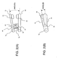
- FIG. 2(A) is a front view showing a configuration example of the biologic information detecting apparatus of the second embodiment
- FIG. 2(B) is a plan view showing a configuration example of the biologic information detecting apparatus.
- the spring 70 for shortening the interval between the other end of the first arm 31 and the other end of the second arm 32 is provided and, in addition, a latch mechanism 71 for preventing the interval between the other end of the first arm 31 and the other end of the second arm 32 from widening is also provided.
- the spring 70 shown in FIG. 2(A) works in the direction of widening the interval between one end of the first arm 31 and one end of the second arm 32.
- the interval between sensors 33 and 34 is widened by pinching one end of the first arm 31 and one end of the second arm 32 to sandwich a living body and the spring 70 is released.
- the sensors 33 and 34 are tightly attached to the living body.
- the latch mechanism 71 maintains the state where the sensors 33 and 34 are tightly attached to the living body.
- FIG. 3 shows a state where the latch mechanism is locked, and FIG. 3(B) shows a state where the latch mechanism is released.
- the plate spring 74 is temporarily retained by the nail 75 for latch, thereby regulating entrance of the supporting member B 77 to the supporting member A 76.
- widening of the interval between the first and second arms 31 and 32 is regulated. That is, it suppresses dropping of the biologic information detecting apparatus once sandwiching the living body.
- the interval between the other ends of the pair of arms can be adjusted by the distance varying mechanism provided for the spindle, and close attachment of the sensors attached to the arms to a living body can be continued by the latch that temporarily regulates widening of the interval between the other ends of the pair of arms. Consequently, biologic information can be detected by the small and light apparatus which can be stably attached in a proper position with a proper contact pressure in accordance with the shape of an individual.
- a biologic information detecting apparatus of a third embodiment is similar to the above-described biologic information detecting apparatus except that an adjusting screw on which a sensor is mounted or an adjusting screw on which a sensor is mounted and which has the function of adjusting at least one of the interval between the sensor and the surface of the first arm, and the interval between the sensor and the surface of the second arm is provided for the first arm and/or the second arm.
- FIG. 4(A) is a front view showing a configuration example of the biologic information detecting apparatus of the embodiment
- FIG. 4(B) is a front view showing a configuration example of the biologic information detecting apparatus of the embodiment.
- FIG. 4 and subsequent diagrams in order to avoid complication of the drawings, indication of names of part of the components is not shown.
- the first arm 31 has an adjusting screw 42
- the sensor 33 is mounted on the adjusting screw 42
- the interval between the sensor 33 and the sensor 34 provided for the second arm 32 is adjusted by the adjusting screw 42. It is optional to provide a rotating mechanism and a latch mechanism.
- the mechanism of the adjusting screw 42 may be a mechanism for adjusting the interval between the sensors 33 and 34 by adjusting the position of the sensor 33 by rotating a screw or a mechanism for adjusting the interval between the sensors 33 and 34, by adjusting the position of the sensor 33 by friction and fixing the position by a fixing screw.
- the interval between the sensors 33 and 34 is finely adjusted by an adjusting screw in accordance with an individual difference of the shape of the tragus, so that the sensors 33 and 34 can be attached to the tragus with proper contact pressure.
- the tragus of the auricle will be described as an example of the projection of the auricle of a human body.
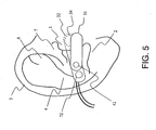
- FIG. 5 shows an example of attachment of the biologic information detecting apparatus to an auricle.
- the biologic information detecting apparatus is attached so as to come into contact with the tragus 1 from both sides so that the sensor 33 of the first arm 31 is in contact with the outside of the tragus 1, and the sensor 34 of the second arm 32 is in contact with the inside of the tragus 1. Since part of the second arm 32 and the sensor 34 are on the inside of the tragus 1, they are shown by broken lines.
- the positions of the sensors 33 and 34 are adjusted by the distance varying mechanism 40 or the rotating mechanism 41 in correspondence with the individual difference of the shape of the tragus 1. Therefore, the sensors 33 and 34 can be attached in a proper position in the tragus 1 in a proper contact state. It is option to provide the rotating mechanism and the latch mechanism.
- a biologic information detecting apparatus of a fifth embodiment relates to the case where the above-described biologic information detecting apparatus further has an ear attachment part that surrounds the base of an auricle.
- FIG. 6 (A) shows a configuration example of the biologic information detecting apparatus of the fifth embodiment
- FIG. 6(B) shows a state where the biologic information detecting apparatus of the embodiment is attached to the auricle.
- the first arm 31 has an ear attachment mechanism 46.
- the ear attachment mechanism 46 is a mechanism for fixing the biologic information detecting apparatus to the auricle by being extended from the base of the auricle to the back side of a helix 5 so as to surround the base of the auricle as shown in FIG. 6(B) .
- the ear attachment may have a ring shape extending along an auricle.
- the ear attachment mechanism may have a structure that surrounds the base of an auricle and its ring shape is closed by a hook. Further, the degree of closing of the closed ring may be adjusted with a stopper.
- the material of the ear attachment may be a metal having plasticity, solder alloy, zinc alloy, brass, copper alloy, aluminum alloy, stainless steel, Ni alloy, tin alloy, or shape memory alloy.
- resin materials plastics, polyvinyl chloride resin, acrylic resin, ABS resin, MC nylon, fluororesin (PTFE), polycarbonate, polypropylene, polyethylene silicone resin, polyurethane resin, or natural rubber may be used. By selecting such materials, the individual differences such as the size of an auricle of a subject can be absorbed.
- the biologic information detecting apparatus of the embodiment has the ear attachment mechanism 46 which hangs on an auricle so as to surround the base of the auricle, so that a deviation from the position of the tragus of the apparatus due to the dead load of the apparatus or the motion of the subject can be prevented.
- the biologic information detecting apparatus is stably fixed to the auricle, and biologic information can be detected more stably.
- the ear attachment mechanism 46 may have a structure which is detachable from the body of the biologic information apparatus, and the ear attachment mechanism 46 of a size adapted to the subject can be selected.
- a biologic information detecting apparatus of a sixth embodiment is obtained by further providing the above-described biologic information detecting apparatus with a cushion provided on the auricle side of an arm disposed on the auricle side of the pair of arms, a magnet provided for at least one of the arm provided with the cushion and the ear attachment, and a magnet or a magnetic member provided for the other one of them.
- FIG. 7 is a diagram showing a state where the biologic information detecting apparatus of the sixth embodiment is supposedly attached to the auricle.
- FIG. 7 is a schematic diagram in which the auricle is shown in section along a horizontal plane near the tragus 1 viewed from above the head of a living body, and an attachment state of the biologic information detecting apparatus to the living body is viewed from above the head of the living body.
- a cushion 45 is disposed on the outside of the second arm 32.
- the cushion 45 has a magnet 47 in a position in contact with the auricle.
- the ear attachment mechanism 46 has a magnet 48 in a position in contact with the auricle on the back side of the auricle.
- the magnets 47 and 48 are on both sides of an antihelix 4 of the auricle and have polarities so that magnetic forces of the magnets 47 and 48 act each other.
- the magnets 47 and 48 are fixed in contact with the auricle.
- the apparatus can be attached for long time without giving pain to the subject.
- the cushion 45 further includes the magnet on the side in contact with the auricle
- the ear attachment mechanism 46 further includes the magnet on the side in contact with the auricle so that their magnetic forces act each other.
- the biologic information detecting apparatus is fixed to the auricle more comfortably, and biologic information can be detected more stably.
- the two magnets 47 and 48 are used in FIG. 7 , one magnet and a magnetic member instead of the other magnet may be used.
- the magnets 47 and 48 may be provided in the cushion 45 and the ear attachment mechanism 46, respectively.
- the biologic information detecting apparatus of the embodiment which is small and light can be attached more comfortably to a tragus of a living body in a proper position with a proper contact pressure in correspondence with variations in the body shape of an individual, and can detect biologic information more stably and continuously.
- the body of the above-described biologic information detecting apparatus is attached to one of right and left auricles of a human body, and the apparatus further includes a bridge connecting the pair of arms and an auricle to which the pair of arms is not attached, and a power supply unit disposed in some midpoint of the bridge and driving a sensor.
- FIG. 8 shows an attachment state of the biologic information detecting apparatus of the seventh embodiment.
- 30 denotes a biologic information detecting apparatus
- 80 denotes a bridge
- 82 indicates a power supply unit.
- the body of the biologic information detecting apparatus is attached to one of the right and left auricles of a human body, and a power supply unit for driving a sensor is disposed in a bridge connecting the pair of arms and the auricle to which the pair of arms is not attached via the back part of the head of the human body.
- a pump for supplying/exhausting air to/from the cuff and also to the power supply unit may be disposed.
- the material of the bridge may be a metal having plasticity, solder alloy, zinc alloy, brass, copper alloy, aluminum alloy, stainless steel, Ni alloy, tin alloy, or shape memory alloy.
- resin materials plastics, polyvinyl chloride resin, acrylic resin, ABS resin, MC nylon, fluororesin (PTFE), polycarbonate, polypropylene, polyethylene silicone resin, or polyurethane resin may be used. By selecting such materials, the individual differences such as the size of the head of a subject can be absorbed.
- the bridge extends along the back part of the head, the bridge may extend along the top of the head or the under the chin.
- the power supply unit By disposing the power supply unit on the head, portability and management of the biologic information detecting apparatus can be facilitated.
- the pump By disposing the pump on the head, a pipe can be easily fixed and noise can be reduced at the time of detection of biologic information.
- the biologic information detecting apparatus can be stably attached to the auricle.
- the power supply unit separately from the arm side, the weight of the arm side can be reduced.
- a biologic information detecting apparatus is obtained by providing the above-described biologic information detecting apparatus with, as shown in FIGS. 9(A) and 9(B) , for example, a supporting member 57 in place of the sensor 33 shown in FIG. 1 and a cuff 56 in place of the sensor 34.
- the cuff 56 has therein a light emitting element 61 and a light receiving element 62.
- the cuff 56 further has an air pipe 36 for supplying air.
- FIG. 9(B) is an enlarged view of a portion of the supporting member 57 and the cuff 56 in a state where the biologic information detecting apparatus of FIG. 9(A) is attached to the tragus 1.
Landscapes
- Health & Medical Sciences (AREA)
- Life Sciences & Earth Sciences (AREA)
- Engineering & Computer Science (AREA)
- Molecular Biology (AREA)
- Animal Behavior & Ethology (AREA)
- Pathology (AREA)
- Physics & Mathematics (AREA)
- Biomedical Technology (AREA)
- Heart & Thoracic Surgery (AREA)
- Medical Informatics (AREA)
- Otolaryngology (AREA)
- Surgery (AREA)
- Biophysics (AREA)
- General Health & Medical Sciences (AREA)
- Public Health (AREA)
- Veterinary Medicine (AREA)
- Cardiology (AREA)
- Physiology (AREA)
- Vascular Medicine (AREA)
- Signal Processing (AREA)
- Measuring Pulse, Heart Rate, Blood Pressure Or Blood Flow (AREA)
Claims (6)
- Vorrichtung zur Erfassung biologischer Informationen, mit:zwei Armen (31, 32), die einander zugewandt und so eingerichtet sind, dass sie einen Tragus als vorstehendes Teil einer Aurikel im menschlichen Körper durch einen Arm, der an einer der Seitenflächenseiten des vorstehenden Teils angeordnet ist, und einen Arm zwischen sich klemmen, der an der anderen Seitenflächenseite des vorstehenden Teils angeordnet ist,einer Spindel (35), die die zwei Arme (31, 32) an einem Ende jedes der Arme (31, 32) verbindet,einem Abstandsänderungsmechanismus (40), der für die Spindel (35) vorgesehen ist und einen Zwischenraum zwischen den anderen Enden der zwei Arme (31, 32) einstellt,einer Manschette (55, 56) zum Drücken eines lebenden Körpers, die am anderen Ende wenigstens eines der Arme (31, 32) befestigt ist und auf der dem anderen Arm (31, 32) zugewandten Seite befestigt ist, undeinem Sensor (33, 34) zur Erfassung der biologischen Information, der am anderen Ende wenigstens eines der Arme (31, 32) befestigt ist und auf der dem anderen Arm (31, 32) zugewandten Seite befestigt ist,wobeidie biologische Information ein Blutdruck ist,die Manschette (55) von dem Arm, an dem die Manschette (55) befestigt ist, abnehmbar ist, indem der Teil am Vorderende des Arms, der die Manschette (55) aufweist, in Richtung der Längsachse des Arms, an dem die Manschette befestigt ist, herausgezogen wird, undein Dichtelement (86) zwischen dem Teil am Vorderende des Arms (31) und dem Körper des Arms befestigt ist, um einen Luftaustritt aus einer Leitung zum Zuführen/Abführen von Luft zu bzw. aus der Manschette (55) zu verhindern.
- Vorrichtung zur Erfassung biologischer Informationen nach Anspruch 1, ferner mit einem Drehmechanismus (41) zum Drehen wenigstens eines der zwei Arme (31, 32) um die Spindel (35) als Mittelachse.
- Vorrichtung zur Erfassung biologischer Informationen nach Anspruch 1 oder 2, ferner mit einer Ohrhalterung, die um die Basis der Aurikel gelegt wird.
- Vorrichtung zur Erfassung biologischer Informationen nach Anspruch 3, ferner mit:einem Polster (45), das auf einer Aurikelseite eines Arms (32) vorgesehen ist, der bei den zwei Armen (31, 32) auf der Aurikelseite angeordnet ist,einem Magneten (47), der für den mit dem Polster (45) versehenen Arm (32) und/oder die Ohrhalterung vorgesehen ist, undeinem Magneten (48) oder einem magnetischen Element, der bzw. das für das jeweils andere der beiden Teile Arm (32) und Ohrhalterung vorgesehen ist.
- Vorrichtung zur Erfassung biologischer Informationen nach Anspruch 1 oder 2, ferner mit:einer Ohrhalterung, die an der Basis der Aurikel aufgehängt wird, undeinem Netzgerät (82), das in der Ohrhalterung angeordnet ist und den Sensor (33) ansteuert.
- Vorrichtung zur Erfassung biologischer Informationen nach einem der Ansprüche 1 bis 4, ferner mit:einer Brücke (80), die so eingerichtet ist, dass sie sich zwischen der rechten und der linken Aurikel erstreckt, und die die zwei an der rechten oder der linken Aurikel angebrachten Arme (31, 32) mit der anderen Aurikel verbindet, an der die zwei Arme (31, 32) nicht angebracht sind, undeinem Netzgerät (82), das etwa an einem Mittelpunkt der Brücke (80) angeordnet ist und den Sensor (33) ansteuert.
Applications Claiming Priority (2)
| Application Number | Priority Date | Filing Date | Title |
|---|---|---|---|
| JP2004293238A JP4460414B2 (ja) | 2004-10-06 | 2004-10-06 | 血圧計 |
| EP05790242A EP1806094A4 (de) | 2004-10-06 | 2005-10-04 | Vorrichtung zum nachweis von biologischen informationen |
Related Parent Applications (2)
| Application Number | Title | Priority Date | Filing Date |
|---|---|---|---|
| EP05790242.1 Division | 2005-10-04 | ||
| EP05790242A Division EP1806094A4 (de) | 2004-10-06 | 2005-10-04 | Vorrichtung zum nachweis von biologischen informationen |
Publications (2)
| Publication Number | Publication Date |
|---|---|
| EP2245984A1 EP2245984A1 (de) | 2010-11-03 |
| EP2245984B1 true EP2245984B1 (de) | 2015-12-23 |
Family
ID=36142700
Family Applications (6)
| Application Number | Title | Priority Date | Filing Date |
|---|---|---|---|
| EP10005858.5A Expired - Lifetime EP2229877B1 (de) | 2004-10-06 | 2005-10-04 | Vorrichtung zur Detektion biologischer Information |
| EP05790242A Withdrawn EP1806094A4 (de) | 2004-10-06 | 2005-10-04 | Vorrichtung zum nachweis von biologischen informationen |
| EP10005861.9A Expired - Lifetime EP2253267B1 (de) | 2004-10-06 | 2005-10-04 | Biologische Informationsdetektionsvorrichtung |
| EP10005862.7A Expired - Lifetime EP2243424B1 (de) | 2004-10-06 | 2005-10-04 | Biologische Informationsdetektionsvorrichtung |
| EP10005859.3A Expired - Lifetime EP2238895B1 (de) | 2004-10-06 | 2005-10-04 | Vorrichtung zur Detektion biologischer Information |
| EP10005860.1A Expired - Lifetime EP2245984B1 (de) | 2004-10-06 | 2005-10-04 | Biologische Informationsdetektionsvorrichtung |
Family Applications Before (5)
| Application Number | Title | Priority Date | Filing Date |
|---|---|---|---|
| EP10005858.5A Expired - Lifetime EP2229877B1 (de) | 2004-10-06 | 2005-10-04 | Vorrichtung zur Detektion biologischer Information |
| EP05790242A Withdrawn EP1806094A4 (de) | 2004-10-06 | 2005-10-04 | Vorrichtung zum nachweis von biologischen informationen |
| EP10005861.9A Expired - Lifetime EP2253267B1 (de) | 2004-10-06 | 2005-10-04 | Biologische Informationsdetektionsvorrichtung |
| EP10005862.7A Expired - Lifetime EP2243424B1 (de) | 2004-10-06 | 2005-10-04 | Biologische Informationsdetektionsvorrichtung |
| EP10005859.3A Expired - Lifetime EP2238895B1 (de) | 2004-10-06 | 2005-10-04 | Vorrichtung zur Detektion biologischer Information |
Country Status (7)
| Country | Link |
|---|---|
| US (6) | US8657752B2 (de) |
| EP (6) | EP2229877B1 (de) |
| JP (1) | JP4460414B2 (de) |
| KR (1) | KR100875777B1 (de) |
| CN (1) | CN100479745C (de) |
| TW (1) | TW200616585A (de) |
| WO (1) | WO2006038627A1 (de) |
Families Citing this family (29)
| Publication number | Priority date | Publication date | Assignee | Title |
|---|---|---|---|---|
| CN101897582B (zh) * | 2003-10-09 | 2012-11-21 | 日本电信电话株式会社 | 生物体信息采集系统 |
| JP5021179B2 (ja) * | 2005-04-08 | 2012-09-05 | テルモ株式会社 | 血圧測定装置 |
| US20100004518A1 (en) | 2008-07-03 | 2010-01-07 | Masimo Laboratories, Inc. | Heat sink for noninvasive medical sensor |
| US8630691B2 (en) | 2008-08-04 | 2014-01-14 | Cercacor Laboratories, Inc. | Multi-stream sensor front ends for noninvasive measurement of blood constituents |
| JP4480785B1 (ja) * | 2009-04-23 | 2010-06-16 | メディカルトラスト株式会社 | 生体情報検出装置 |
| US20100331631A1 (en) * | 2009-06-30 | 2010-12-30 | Nellcor Puritan Bennett Llc | Oxygen saturation ear sensor design that optimizes both attachment method and signal quality |
| KR20130027679A (ko) * | 2011-09-08 | 2013-03-18 | 한국전자통신연구원 | 맥박 측정 장치 및 이를 이용한 맥박 정보 획득 방법 |
| TWI486147B (zh) * | 2011-10-04 | 2015-06-01 | Univ Nat Taiwan Science Tech | 即時生理信號量測及回饋系統 |
| TW201344502A (zh) * | 2012-04-20 | 2013-11-01 | Utechzone Co Ltd | 耳戴式眼控裝置 |
| US10318495B2 (en) | 2012-09-24 | 2019-06-11 | Sandisk Technologies Llc | Snapshots for a non-volatile device |
| WO2014116942A2 (en) * | 2013-01-28 | 2014-07-31 | Valencell, Inc. | Physiological monitoring devices having sensing elements decoupled from body motion |
| IL225182A (en) * | 2013-03-12 | 2016-06-30 | A D Integrity Ltd | Install earlobe sensors for medical monitoring |
| EP2939593A1 (de) * | 2014-05-02 | 2015-11-04 | Lindberg, Lars-Göran | Vorrichtung und System zur Bestimmung der physiologischen Parameter des Sternumknochens |
| KR102339922B1 (ko) * | 2014-09-01 | 2021-12-16 | 삼성전자주식회사 | 생체 신호를 측정하는 방법 및 그 장치 |
| JP6219889B2 (ja) * | 2014-09-08 | 2017-10-25 | 京セラ株式会社 | 音響機器 |
| CN105640532B (zh) * | 2014-11-11 | 2019-04-16 | 中国科学院上海高等研究院 | 耳戴式心率监测装置及方法 |
| CN106137163A (zh) * | 2015-04-07 | 2016-11-23 | 刘红超 | 一种心率测定装置和方法 |
| CN106137161A (zh) * | 2015-04-07 | 2016-11-23 | 刘红超 | 一种心率和血压测定装置和方法 |
| TWI595859B (zh) | 2016-01-08 | 2017-08-21 | 豪展醫療科技股份有限公司 | 生理狀態監測裝置 |
| US11350837B2 (en) | 2016-03-30 | 2022-06-07 | Elfi-Tech Ltd. | Method and apparatus for optically measuring blood pressure |
| US11134901B2 (en) | 2016-03-30 | 2021-10-05 | Elfi-Tech Ltd. | Method and apparatus for optically measuring blood pressure |
| PL3509637T3 (pl) | 2016-09-06 | 2025-03-10 | Chugai Seiyaku Kabushiki Kaisha | Sposoby zastosowania dwuswoistego przeciwciała, które rozpoznaje czynnik krzepnięcia IX i/lub aktywowany czynnik krzepnięcia IX oraz czynnik krzepnięcia X i/lub aktywowany czynnik krzepnięcia X |
| NL2017538B1 (en) * | 2016-09-27 | 2018-04-04 | Agis Automatisering B V | Wireless vital sign monitoring |
| EP3525674B1 (de) | 2016-10-12 | 2021-12-08 | Elfi-Tech Ltd. | Verfahren und vorrichtung zur optischen messung des blutdrucks |
| DK3627856T3 (da) * | 2018-09-19 | 2023-11-13 | Sonion Nederland Bv | Hus, der omfatter en sensor |
| US11357412B2 (en) | 2018-11-20 | 2022-06-14 | 42 Health Sensor Holdings Ltd. | Wearable cardiovascular monitoring device |
| KR20220129033A (ko) | 2020-01-13 | 2022-09-22 | 마시모 코오퍼레이션 | 생리학적 파라미터 모니터링 기능이 있는 웨어러블 디바이스 |
| IL296541A (en) * | 2020-03-18 | 2022-11-01 | 42Health Sensor Holdings Ltd | A multi-sensor biometric information monitoring device |
| EP4370022A1 (de) | 2021-07-13 | 2024-05-22 | Masimo Corporation | Tragbare vorrichtung mit überwachung physiologischer parameter |
Citations (1)
| Publication number | Priority date | Publication date | Assignee | Title |
|---|---|---|---|---|
| EP1217941B1 (de) * | 1999-09-28 | 2003-06-25 | Orsense Ltd. | Optische vorrichtung zur nichtinvasiven messung von blutbezüglichen signalen mittels eines fingerhalters |
Family Cites Families (37)
| Publication number | Priority date | Publication date | Assignee | Title |
|---|---|---|---|---|
| US1390495A (en) * | 1919-09-09 | 1921-09-13 | George B Campbell | Hide-coupler |
| US3227155A (en) * | 1961-07-10 | 1966-01-04 | Honeywell Inc | Sphygmomanometric measuring apparatus |
| US3412729A (en) * | 1965-08-30 | 1968-11-26 | Nasa Usa | Method and apparatus for continuously monitoring blood oxygenation, blood pressure, pulse rate and the pressure pulse curve utilizing an ear oximeter as transducer |
| BE790454A (fr) | 1971-10-23 | 1973-04-24 | Philips Nv | Enregistreur de grandeurs physiologiques |
| US3815583A (en) * | 1972-01-19 | 1974-06-11 | T Scheidt | Pulse monitoring system |
| US4029083A (en) * | 1975-05-12 | 1977-06-14 | Baylor Carl S | Probe for audiometric apparatus |
| DE3275900D1 (en) * | 1981-08-21 | 1987-05-07 | Nat Res Dev | Blood pressure measurement |
| US4685464A (en) * | 1985-07-05 | 1987-08-11 | Nellcor Incorporated | Durable sensor for detecting optical pulses |
| US5046580A (en) * | 1990-08-17 | 1991-09-10 | Barton James I | Ear plug assembly for hearing aid |
| US5267566A (en) * | 1991-03-07 | 1993-12-07 | Maged Choucair | Apparatus and method for blood pressure monitoring |
| DE4219687C2 (de) | 1992-06-16 | 1994-05-05 | Richard Herbst | Verfahren zum Betrieb einer Spritzgießmaschine mit Werkzeugsicherung |
| US6172743B1 (en) * | 1992-10-07 | 2001-01-09 | Chemtrix, Inc. | Technique for measuring a blood analyte by non-invasive spectrometry in living tissue |
| US5600730A (en) * | 1992-11-16 | 1997-02-04 | Kenning; Peggy J. | Swimming training device |
| JPH0655603U (ja) * | 1993-01-16 | 1994-08-02 | 三菱鉛筆株式会社 | 心搏数測定器 |
| US5339810A (en) * | 1993-05-03 | 1994-08-23 | Marquette Electronics, Inc. | Pulse oximetry sensor |
| US5971931A (en) * | 1994-03-29 | 1999-10-26 | Raff; Gilbert Lewis | Biologic micromonitoring methods and systems |
| JP3270916B2 (ja) * | 1994-04-11 | 2002-04-02 | 日本光電工業株式会社 | 光センサ |
| JP3326580B2 (ja) * | 1995-05-08 | 2002-09-24 | 日本光電工業株式会社 | 生体組織透過光センサ |
| JPH09122083A (ja) | 1995-10-30 | 1997-05-13 | Noboru Akasaka | 常時装着可能な患者モニタ装置 |
| JPH10108846A (ja) * | 1996-10-03 | 1998-04-28 | Nippon Koden Corp | 生体信号検出用挟持具 |
| JPH10108845A (ja) | 1996-10-03 | 1998-04-28 | Nippon Koden Corp | 生体信号検出用挟持具 |
| JP3758824B2 (ja) * | 1997-08-06 | 2006-03-22 | 倉敷紡績株式会社 | 生体の圧力一定化装置 |
| JPH11128174A (ja) | 1997-10-27 | 1999-05-18 | Akkusu Kk | 緊急通報装置及び緊急通報システム |
| JP3853053B2 (ja) * | 1997-12-17 | 2006-12-06 | 松下電器産業株式会社 | 生体情報測定装置 |
| IL124787A0 (en) * | 1998-06-07 | 1999-01-26 | Itamar Medical C M 1997 Ltd | Pressure applicator devices particularly useful for non-invasive detection of medical conditions |
| IL135077A0 (en) * | 2000-03-15 | 2001-05-20 | Orsense Ltd | A probe for use in non-invasive measurements of blood related parameters |
| JP2002238865A (ja) | 2001-02-20 | 2002-08-27 | Mitsubishi Electric Corp | 耳朶装着型脈波計測装置 |
| JP2005501576A (ja) * | 2001-05-07 | 2005-01-20 | カーディオセーフ・インターナショナル・アクチェンゲゼルシャフト | 患者監視構成 |
| ATE369787T1 (de) * | 2001-06-20 | 2007-09-15 | Purdue Research Foundation | Druckmanschette mit körperbeleuchtung zur verwendung bei der optischen nichtinvasiven messung von blutparametern |
| KR100493157B1 (ko) * | 2002-08-02 | 2005-06-03 | 삼성전자주식회사 | 생체신호 측정에 사용되는 프로브 및 이를 포함하는생체신호 측정용 시스템 |
| US7341559B2 (en) * | 2002-09-14 | 2008-03-11 | Masimo Corporation | Pulse oximetry ear sensor |
| CN101897582B (zh) * | 2003-10-09 | 2012-11-21 | 日本电信电话株式会社 | 生物体信息采集系统 |
| US7254434B2 (en) * | 2003-10-14 | 2007-08-07 | Masimo Corporation | Variable pressure reusable sensor |
| JP4559281B2 (ja) | 2005-04-08 | 2010-10-06 | テルモ株式会社 | 血圧測定装置 |
| WO2006109520A1 (ja) * | 2005-04-08 | 2006-10-19 | Terumo Kabushiki Kaisha | 血圧測定装置 |
| US7869850B2 (en) * | 2005-09-29 | 2011-01-11 | Nellcor Puritan Bennett Llc | Medical sensor for reducing motion artifacts and technique for using the same |
| US7555327B2 (en) * | 2005-09-30 | 2009-06-30 | Nellcor Puritan Bennett Llc | Folding medical sensor and technique for using the same |
-
2004
- 2004-10-06 JP JP2004293238A patent/JP4460414B2/ja not_active Expired - Lifetime
-
2005
- 2005-10-04 EP EP10005858.5A patent/EP2229877B1/de not_active Expired - Lifetime
- 2005-10-04 EP EP05790242A patent/EP1806094A4/de not_active Withdrawn
- 2005-10-04 WO PCT/JP2005/018369 patent/WO2006038627A1/ja not_active Ceased
- 2005-10-04 EP EP10005861.9A patent/EP2253267B1/de not_active Expired - Lifetime
- 2005-10-04 KR KR20077005092A patent/KR100875777B1/ko not_active Expired - Lifetime
- 2005-10-04 EP EP10005862.7A patent/EP2243424B1/de not_active Expired - Lifetime
- 2005-10-04 CN CNB200580029738XA patent/CN100479745C/zh not_active Expired - Lifetime
- 2005-10-04 EP EP10005859.3A patent/EP2238895B1/de not_active Expired - Lifetime
- 2005-10-04 EP EP10005860.1A patent/EP2245984B1/de not_active Expired - Lifetime
- 2005-10-04 US US11/575,294 patent/US8657752B2/en active Active
- 2005-10-05 TW TW094134853A patent/TW200616585A/zh not_active IP Right Cessation
-
2011
- 2011-07-14 US US13/183,320 patent/US8382675B2/en not_active Expired - Lifetime
- 2011-07-14 US US13/183,368 patent/US8652054B2/en not_active Expired - Lifetime
- 2011-07-14 US US13/183,345 patent/US8652052B2/en not_active Expired - Lifetime
- 2011-07-14 US US13/183,338 patent/US8382676B2/en not_active Expired - Lifetime
- 2011-07-14 US US13/183,351 patent/US8652053B2/en not_active Expired - Lifetime
Patent Citations (1)
| Publication number | Priority date | Publication date | Assignee | Title |
|---|---|---|---|---|
| EP1217941B1 (de) * | 1999-09-28 | 2003-06-25 | Orsense Ltd. | Optische vorrichtung zur nichtinvasiven messung von blutbezüglichen signalen mittels eines fingerhalters |
Also Published As
| Publication number | Publication date |
|---|---|
| US20110295132A1 (en) | 2011-12-01 |
| EP2243424A1 (de) | 2010-10-27 |
| US8382676B2 (en) | 2013-02-26 |
| US8652052B2 (en) | 2014-02-18 |
| EP2238895B1 (de) | 2016-06-22 |
| EP2229877B1 (de) | 2016-12-21 |
| EP2229877A1 (de) | 2010-09-22 |
| KR20070045309A (ko) | 2007-05-02 |
| JP4460414B2 (ja) | 2010-05-12 |
| US8382675B2 (en) | 2013-02-26 |
| WO2006038627A1 (ja) | 2006-04-13 |
| EP1806094A1 (de) | 2007-07-11 |
| JP2006102164A (ja) | 2006-04-20 |
| TWI374725B (de) | 2012-10-21 |
| EP1806094A4 (de) | 2010-04-07 |
| US8657752B2 (en) | 2014-02-25 |
| US20110295133A1 (en) | 2011-12-01 |
| EP2245984A1 (de) | 2010-11-03 |
| US20110295081A1 (en) | 2011-12-01 |
| EP2253267B1 (de) | 2015-12-23 |
| CN100479745C (zh) | 2009-04-22 |
| US8652054B2 (en) | 2014-02-18 |
| KR100875777B1 (ko) | 2008-12-26 |
| US20110295092A1 (en) | 2011-12-01 |
| US20110295131A1 (en) | 2011-12-01 |
| US8652053B2 (en) | 2014-02-18 |
| EP2253267A1 (de) | 2010-11-24 |
| EP2243424B1 (de) | 2015-12-23 |
| EP2238895A1 (de) | 2010-10-13 |
| US20080319325A1 (en) | 2008-12-25 |
| CN101014282A (zh) | 2007-08-08 |
| TW200616585A (en) | 2006-06-01 |
Similar Documents
| Publication | Publication Date | Title |
|---|---|---|
| US8652052B2 (en) | Biologic information detecting apparatus | |
| CN101897581B (zh) | 生物体信息检测装置 | |
| EP1941831A1 (de) | Manschetten zur messung des blutdrucks und blutdruckmessgerät | |
| JP4401923B2 (ja) | 血圧計測装置 | |
| JP4767586B2 (ja) | 血圧測定装置 |
Legal Events
| Date | Code | Title | Description |
|---|---|---|---|
| PUAI | Public reference made under article 153(3) epc to a published international application that has entered the european phase |
Free format text: ORIGINAL CODE: 0009012 |
|
| AC | Divisional application: reference to earlier application |
Ref document number: 1806094 Country of ref document: EP Kind code of ref document: P |
|
| AK | Designated contracting states |
Kind code of ref document: A1 Designated state(s): DE GB |
|
| 17P | Request for examination filed |
Effective date: 20110411 |
|
| RIN1 | Information on inventor provided before grant (corrected) |
Inventor name: TOCHIKUBO, OSAMU Inventor name: AIHARA, KIMIHISA Inventor name: TATARA, NAOE Inventor name: MINO, SHINJI Inventor name: HAYASHIDA, SHOICHI Inventor name: SHIMADA, JUNICHI Inventor name: MIURA, HIDETOSHI Inventor name: SUDO, SHOICHI Inventor name: KOIZUMI, HIROSHI Inventor name: OGUCHI, TAISUKE |
|
| 17Q | First examination report despatched |
Effective date: 20110609 |
|
| REG | Reference to a national code |
Ref country code: DE Ref legal event code: R079 Ref document number: 602005048167 Country of ref document: DE Free format text: PREVIOUS MAIN CLASS: A61B0005000000 Ipc: A61B0005022000 |
|
| GRAP | Despatch of communication of intention to grant a patent |
Free format text: ORIGINAL CODE: EPIDOSNIGR1 |
|
| RIC1 | Information provided on ipc code assigned before grant |
Ipc: A61B 5/022 20060101AFI20150429BHEP |
|
| INTG | Intention to grant announced |
Effective date: 20150529 |
|
| RIN1 | Information on inventor provided before grant (corrected) |
Inventor name: AIHARA, KIMIHISA Inventor name: MIURA, HIDETOSHI Inventor name: KOIZUMI, HIROSHI Inventor name: TOCHIKUBO, OSAMU Inventor name: HAYASHIDA, SHOICHI Inventor name: SHIMADA, JUNICHI Inventor name: SUDO, SHOICHI Inventor name: MINO, SHINJI Inventor name: OGUCHI, TAISUKE Inventor name: TATARA, NAOE |
|
| GRAS | Grant fee paid |
Free format text: ORIGINAL CODE: EPIDOSNIGR3 |
|
| GRAA | (expected) grant |
Free format text: ORIGINAL CODE: 0009210 |
|
| AC | Divisional application: reference to earlier application |
Ref document number: 1806094 Country of ref document: EP Kind code of ref document: P |
|
| AK | Designated contracting states |
Kind code of ref document: B1 Designated state(s): DE GB |
|
| REG | Reference to a national code |
Ref country code: GB Ref legal event code: FG4D |
|
| REG | Reference to a national code |
Ref country code: DE Ref legal event code: R096 Ref document number: 602005048167 Country of ref document: DE |
|
| REG | Reference to a national code |
Ref country code: DE Ref legal event code: R097 Ref document number: 602005048167 Country of ref document: DE |
|
| PLBE | No opposition filed within time limit |
Free format text: ORIGINAL CODE: 0009261 |
|
| STAA | Information on the status of an ep patent application or granted ep patent |
Free format text: STATUS: NO OPPOSITION FILED WITHIN TIME LIMIT |
|
| 26N | No opposition filed |
Effective date: 20160926 |
|
| PGFP | Annual fee paid to national office [announced via postgrant information from national office to epo] |
Ref country code: DE Payment date: 20241021 Year of fee payment: 20 |
|
| PGFP | Annual fee paid to national office [announced via postgrant information from national office to epo] |
Ref country code: GB Payment date: 20241022 Year of fee payment: 20 |
|
| REG | Reference to a national code |
Ref country code: DE Ref legal event code: R071 Ref document number: 602005048167 Country of ref document: DE |
|
| REG | Reference to a national code |
Ref country code: GB Ref legal event code: PE20 Expiry date: 20251003 |