EP2246077B1 - Dispositif médical d'aspiration sous vide - Google Patents
Dispositif médical d'aspiration sous vide Download PDFInfo
- Publication number
- EP2246077B1 EP2246077B1 EP09159182A EP09159182A EP2246077B1 EP 2246077 B1 EP2246077 B1 EP 2246077B1 EP 09159182 A EP09159182 A EP 09159182A EP 09159182 A EP09159182 A EP 09159182A EP 2246077 B1 EP2246077 B1 EP 2246077B1
- Authority
- EP
- European Patent Office
- Prior art keywords
- tube
- piston
- aspiration device
- vacuum aspiration
- medical vacuum
- Prior art date
- Legal status (The legal status is an assumption and is not a legal conclusion. Google has not performed a legal analysis and makes no representation as to the accuracy of the status listed.)
- Not-in-force
Links
- 238000006073 displacement reaction Methods 0.000 claims abstract description 61
- 238000000034 method Methods 0.000 claims abstract description 13
- 239000012530 fluid Substances 0.000 claims description 46
- 238000007789 sealing Methods 0.000 description 4
- 230000000694 effects Effects 0.000 description 2
- 239000012858 resilient material Substances 0.000 description 2
- 239000000853 adhesive Substances 0.000 description 1
- 230000001070 adhesive effect Effects 0.000 description 1
- 230000001419 dependent effect Effects 0.000 description 1
- 238000011156 evaluation Methods 0.000 description 1
- 238000003466 welding Methods 0.000 description 1
Images


Classifications
-
- A—HUMAN NECESSITIES
- A61—MEDICAL OR VETERINARY SCIENCE; HYGIENE
- A61M—DEVICES FOR INTRODUCING MEDIA INTO, OR ONTO, THE BODY; DEVICES FOR TRANSDUCING BODY MEDIA OR FOR TAKING MEDIA FROM THE BODY; DEVICES FOR PRODUCING OR ENDING SLEEP OR STUPOR
- A61M1/00—Suction or pumping devices for medical purposes; Devices for carrying-off, for treatment of, or for carrying-over, body-liquids; Drainage systems
- A61M1/64—Containers with integrated suction means
- A61M1/67—Containers incorporating a piston-type member to create suction, e.g. syringes
-
- A—HUMAN NECESSITIES
- A61—MEDICAL OR VETERINARY SCIENCE; HYGIENE
- A61M—DEVICES FOR INTRODUCING MEDIA INTO, OR ONTO, THE BODY; DEVICES FOR TRANSDUCING BODY MEDIA OR FOR TAKING MEDIA FROM THE BODY; DEVICES FOR PRODUCING OR ENDING SLEEP OR STUPOR
- A61M1/00—Suction or pumping devices for medical purposes; Devices for carrying-off, for treatment of, or for carrying-over, body-liquids; Drainage systems
- A61M1/80—Suction pumps
- A61M1/81—Piston pumps, e.g. syringes
- A61M1/815—Piston pumps, e.g. syringes the barrel serving as aspiration container, e.g. in a breast pump
Definitions
- the invention relates to a medical vacuum aspiration device and a method of detaching a tube from a medical vacuum aspiration device.
- US 2007 016 1965 discloses a medical vacuum aspiration device consisting of several components which can be easily disassembled and, therefore, easily cleaned and sterilized.
- the medical vacuum aspiration device consists of a collection tube in which the fluid and tissue is collected after a suction process is performed. Additionally, said device has a cannula which is inserted into the body and a plunger used for performing the suction process. The cannula and the collection tube are connected to each other by a fluid conduit inserted into a housing.
- the medical vacuum aspiration device mentioned above has the disadvantage that the total medical aspiration device is large. Therefore, it is difficult to transport the fluid and tissue contained in the collection tube in a compact and secure way to other locations for evaluation after the suction process is performed.
- WO 2008/007892 US 6,264,620 and DE 3005679 disclose a medical vacuum aspiration device having a tube, a piston which is removably coupled with the displacement means and a closure means, respectively. Said closure means is attachable to the inlet opening of the tube after a suction process is performed by the medical vacuum aspiration device.
- the object of the present invention is to provide a medical vacuum aspiration device enabling to transport the suctioned fluid and tissue in a compact and secure way to other locations.
- an advantage of the present invention is that the tube can easily be detached from a displacement means because the displacement means is removably coupled with a plunger arranged within the tube. Additionally, an advantage of the invention is that an inlet opening of the tube can be closed by a closure means so that it is secured that no suctioned fluid and tissue can flow out the tube. As a result, the suctioned fluid and tissue can be transported in a secure way. In addition, an advantage of the invention is that the size of the tube is smaller than the size of the total medical vacuum aspiration device so that the suctioned fluid and tissue can be transported in a compact way to another location.
- a further advantage of the present invention is that the displacement means can be detached from the piston.
- the piston and the displacement means can be easily cleaned, sterilized and reused.
- a user is free to dispose the medical vacuum aspiration device in total or several components thereof.
- a further advantage exists therein that only said components can be disposed. That means that the displacement means can be used several times.
- closure means is arranged at the medical vacuum aspiration device, in particular at the displacement means. With said arrangement it is secured that the closure means does not get lost.
- an advantage of the present invention is achieved in that the piston provides at least one recess. Said recess is engaged with a protrusion of a stopping element so that it is secured that the piston can not be moved further when the displacement means is removed from the piston.
- the medical vacuum aspiration device shown in Fig. 1 comprises a displacement means 5, a piston 4 and a closure means 6.
- the displacement means 5 can be coupled with the piston 4 at one end thereof and can be used to displace the position of the piston 4.
- the closure means 6 is arranged at the end of the displacement means 5 distal to the piston 4.
- the medical vacuum aspiration device 100 comprises a tube 3 for collecting the suctioned fluid and tissue.
- the tube 3 is in the form of a syringe barrel; however, the tube 3 can also have another form than a syringe.
- the tube 3 has a cylindrical form and an elongated flange 33 arranged at one end of the tube 3. Said flange 33 can provide a grip for the user during the suction process.
- the tube 3 comprises an inlet opening for enabling the suctioned fluid and tissue to flow into the tube 3.
- the tube 3 comprises a hollow protrusion 32 including said inlet opening.
- the hollow protrusion 32 extends in a direction away from the tube 3 wherein the suctioned fluid and tissue flows through the hollow protrusion 32 into the tube 3.
- An inner diameter of the hollow protrusion 32 is smaller than an inner diameter of the tube 3.
- the tube 3 At the other end of the tube 3, distal to the hollow protrusion 32, the tube 3 comprises an opening having the same diameter as the tube 3 itself.
- the piston 4 and the displacement means 5 pass through said opening when they are inserted into the tube 3.
- the displacement means 5 is used to displace the piston 4 within the tube 3.
- the inner diameter of the tube 3 is slightly larger than an outer diameter of the piston 4 so that it is secured that the piston 4 can be moved within the tube 3.
- the piston 4 comprises a circumferential groove, extending along the circumference of the piston 4, in which a sealing element 41 like e.g. an O-ring is to be arranged. Said sealing element 41 prevents a fluid and tissue flow out of the tube via the piston 4 and does not hinder the movement of the piston 4.
- the tube 3 comprises at least one hole 31 arranged in its outer surface in the near of the flange 33.
- the hole 31 is made such that a projection 72, arranged at a stopping element 7 and extending from the stopping element 7, can pass through said hole 31.
- the stopping element 7 can be connected to the tube 3 at a position proximal to the elongate flange 33 and includes an arcuate body 71 having two free ends and at least one projection 72 located at one of said ends.
- the projection 72 protrudes radially towards the tube 3.
- the medical vacuum aspiration device comprises a fluid conduit 2 connected to a cannula which is not shown in Fig. 1 .
- the fluid conduit comprises a first portion 21 and a second portion 22 and is formed of a resilient material.
- the first portion 21 is arranged at the end of the fluid conduit 2 directed to the tube and radially extends from the second portion 22 such that the first portion 21 has a plate-shaped form.
- the diameter of the first portion 21 corresponds to the diameter of the tube 3.
- the second portion 22 of the fluid conduit 2 comprises an inner diameter which is similar to the outer diameter of the protrusion 32 of the tube 3.
- the second portion 22 of the fluid conduit can be attached at the protrusion 32 of the tube 3.
- the fluid conduit 2 consists of a resilient material the second portion 22 can adjust oneself to the form of the protrusion 32 of the tube 3.
- the first portion 21 of the fluid conduit 2 is opposite to the front surface of the tube 3 and encloses said front surface so that the sealing properties between the fluid conduit 2 and the tube 3 improve.
- the second portion 22 of the fluid conduit 2 has a similar diameter as the hollow portion of the protrusion 32, the flow of the suctioned fluid and tissue through the fluid conduit 2 into the tube 3 is not hindered by the fluid conduit 2.
- a valve element 1 can be attached on the second portion 22 of the fluid conduit 2 in order to control or prevent a flow of the suctioned fluid and tissue into the tube 3 or out of the tube 3.
- the valve element 1 comprises a pipe element 10 with a hollow 12 having an inner diameter which is marginally larger than an outer diameter of the second portion 22 of the fluid conduit 2 and which is smaller than the diameter of the first portion 21 of the fluid conduit 2.
- the valve element 1 can be attached onto the second portion 22 of the fluid conduit 2 so that the valve element 1 is adjacent to the first portion 21 of the fluid conduit 2.
- valve element 1 comprises a pressing element comprising a button 13 and a clamp stem 14 wherein the button 13 and the clamp stem 14 can be secured together e.g. by adhesives, press fitting, welding or any other connection means usable to connect said components.
- the clamp stem 14 is inserted into an opening 11 of the valve element 1 in a direction transversal to fluid flow direction within the valve element 1.
- the pipe element 10 comprises a further opening opposite to the opening in which the pressing element is inserted as is evident from Fig. 5 .
- Said further opening enables that, in an actuated state of the pressing element, the fluid conduit 2 can be squeezed within said opening by the clamp stem 14.
- the risk of a damage of the fluid conduit 2 due to exerting a press force on the fluid conduit 2 by means of the pressing element is reduced.
- the button 13 can be actuated by a user so that the valve element 1 can be selectively opened and closed.
- the button 13 can have an oval shape and can include a concave contact surface for engagement by a user's finger to effect opening and closing of the valve element 1.
- the button can have other shapes.
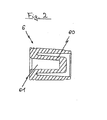
- Fig. 2 shows a cross-sectional view of the closure means 6.
- the closure means 6 comprises a cylindrical form having a hollow.
- the front surface of the closure means 6 proximal to the displacement means 5 comprises an opening.
- the closure means 6 comprises a protrusion 60 protruding from a front surface distal to the displacement means 5 in a direction towards the front surface proximal to the displacement means 5.
- the diameter of the protrusion 60 is smaller than an inner diameter of the hollow of the closure means 6 and corresponds to the inner diameter of the hollow of the protrusion 32 of the tube 3.
- the diameter of the protrusion 60 of the closure means 6 is equal to the inner diameter of the hollow of the protrusion 32 of the tube 3, it is secured that the fluid and tissue can not flow out the tube when the closure means 6 is attached at the protrusion 32 of the tube 3.
- the protrusion 60 protrudes to a position in the near of the front surface of the closure means 6 proximal to the displacement means 5 so that the hollow formed within the closure means 6 has the form of a cup.
- the protrusion 60 itself comprises a recess 61 extending from the front surface of the closure means 6 distal to the displacement means 5 to a position within the protrusion 60.
- An alternative embodiment of the closure means 6 comprises a flange and a protrusion wherein the protrusion extends from the flange.
- the protrusion is adapted to close the hollow protrusion 32 when the closure means 6 is attached to the tube 3.
- the diameter of the flange is larger than the diameter of the protrusion 32 so that the flange abuts against the protrusion 32 of the tube when the closure means 6 is attached to said protrusion 32.
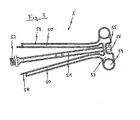
- Fig. 3 shows a cross-sectional view of the displacement means 5.
- the displacement means 5 comprises a handle 53.
- the handle 53 comprises two openings 54 .
- Said openings 54 may be used to enable an easy grasping and moving of the displacement means 5 by the user.
- a recess is provided at the handle 53 in a rearward middle portion.
- a holding element for holding the closure means 6 is provided.
- the handle can just be formed as a t-handle or can comprise only one opening.
- the holding element 53 comprises at least one projection extending in a direction away from the handle 53. Said projection is suitable to encompass the protrusion 60 of the closure means 6 so that the position of the closure means 6 with regard to the displacement means 5 is fixed when the closure means 6 is attached at the displacement means 5.
- two protrusions 55 are provided which can be connected together with a connection portion 56 having the same form as the protrusion 60 when viewed in a direction of a central axis of the displacement means 5.
- the displacement means 5 comprises two locking elements 50 and a fixing element 51 extending all from the handle 53 in a direction away from the holding element 53 towards the piston 4.
- the fixing element 51 is arranged between the locking elements 50 and provides a fixing portion 52 for fixing the displacement means 5 with the piston 4 at its end distal to the handle 53.
- the fixing element 51 comprises a threaded portion for fixing the displacement means 5 in a nut portion of the piston 4.
- Each of the locking elements 50 provides a first part 58 proximal to the fixing element 51 which is longer than a second part 59 distal to the fixing element 51.
- the locking elements 50 can expand radially outward when the displacement means 5 is extracted in a position in which the piston 4 abuts against the projections 72 of the stopping element 7 for example (cf. Fig. 1 ).
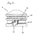
- Fig. 4 shows the piston 4 in a side view.
- the piston 4 comprises a groove 42 in which a sealing ring 41 (cf. Fig. 1 ) can be inserted.
- the piston 4 comprises at least one recess 43, 44, 45 for securing that the piston 4 can not be moved in a longitudinal direction when the displacement means 5 is detached from the piston 4.
- the number of the recesses 43, 44, 45 depends on the number of projections 72 of the stopping element 7.
- the recess comprises a first section 43 parallel with a central axis of the piston 4 and a second section 44 connected with the first section 43 and transversal to said central axis of the piston 4.
- said recess comprises a third section 45 connected with the second section 44 and again parallel with the central axis of the piston 4.
- the third section 45 is arranged parallel and offset with regard to the first section 43.
- Each of said sections 43, 44, 45 is defined by wall portions of the piston 4.
- the piston 4 also comprises a lower part 46 adapted to abut against the projections 72 of the stopping element 7 when the displacement means 5 is extracted to a specific position.
- Fig. 5 shows a cross-sectional view of the medical vacuum aspiration device 100 with the displacement means 5 being in a retracted position. That means that piston 4 is arranged proximal to the valve element 1.
- the pressing element of the valve element 1 is not actuated so that a fluid flow is not disturbed by the clamp stem 14 of the pressing element.
- the locking elements 50 and the fixing element 51 are substantially arranged parallel with each other when the displacement means 5 is in its retracted position. The locking elements 50 and the fixing element 5 stay in said substantial parallel position until the displacement means is extracted to a position in which the second part 59 of the locking element 50 is not guided anymore by the tube.
- each of the locking elements 50 releases radially outward until the first part 58 of the locking elements 50 abuts against an edge 34 (cf. Fig. 5 ) provided at the end of tube 3 proximal to the flange 33.
- an edge 34 cf. Fig. 5
- the position of the displacement means 5 in which the locking elements 50 move radially outwards can be the position in which the lower part 46 of the piston 4 abuts against the projections 72 of the stopping element 7.
- the locking elements 50 move radially outward in an other position than mentioned-above.
- the button 13 of the pressing element is pushed in a direction transverse to the fluid flow and in a direction away from the tube 3 so that the clamp stem 14 of the pressing element 14 is clamped with an edge 15 of the pipe element 10. Thus, no fluid can flow into the tube 3 or out of said tube 3.
- valve element 1 and the fluid conduit 2 are disassembled from the tube 3.
- a force is applied on the valve element 1 in a direction away from the tube 3.
- the closure means 6 is detached from the holding element of the displacement means 5 and attached to the protrusion 32 of the tube 3.
- said closure means 6 prevents that the fluid and tissue can flow out from the protrusion 32 of the tube 3.
- the stopping element 7 is attached to the tube so that the projections 72 pass through the holes 31 of the tube 3. Then the displacement means 5 is extracted until the lower part 46 of the piston 4 abuts against the projections 72 of the stopping element 7.
- the displacement means 5 is rotated until the projections 72 of the stopping element 7 are engaged with the first section 43 of the recess of the piston 4. Then the displacement means 5 is again extracted in the direction away from the tube 3 until the projections 72 of the stopping element 7 abut against a wall portion of the first section 43 of the piston 4. Thereafter, the displacement means 5 are rotated until the projections 72 of the stopping element abut against a wall portion of the second section 44 of the piston 4. Then, the displacement means 5 are again pulled in a direction away from the tube 3 until the projections 72 of the stopping element 7 abut against a wall portion of the third section 45.
- the displacement means 5 is in a position where it can be detached. Additionally, it is secured that the piston 4 can not be moved in a longitudinal direction anymore because in such case the projections 72 of the stopping element 7 would abut against one of the wall portion of the recess second and/or third section 44, 45 of the piston 4.
Landscapes
- Health & Medical Sciences (AREA)
- Heart & Thoracic Surgery (AREA)
- Vascular Medicine (AREA)
- Engineering & Computer Science (AREA)
- Anesthesiology (AREA)
- Biomedical Technology (AREA)
- Hematology (AREA)
- Life Sciences & Earth Sciences (AREA)
- Animal Behavior & Ethology (AREA)
- General Health & Medical Sciences (AREA)
- Public Health (AREA)
- Veterinary Medicine (AREA)
- External Artificial Organs (AREA)
Claims (13)
- Dispositif médical d'aspiration sous vide (100) comprenant un tube (3), un piston mobile (4) et des moyens de déplacement (5),
dans lequel le piston (4) est agencé à l'intérieur du tube (3), dans lequel le tube (3) comprend une ouverture d'entrée au niveau de son côté d'extrémité,
les moyens de déplacement (5) sont couplés de manière amovible avec le piston (4) et en ce que les moyens de fermeture (6) peuvent être fixés à l'ouverture d'entrée du tube (3) après que le processus d'aspiration a été réalisé par le dispositif d'aspiration de vide médical (100),
caractérisé en ce que :le piston (4) comprend au moins un évidement (43, 44, 45) qui est mis en prise avec une saillie d'un élément de butée (7) lorsque les moyens de déplacement (5) sont retirés du piston afin d'empêcher une rotation du piston (4) et un autre mouvement de ce dernier. - Dispositif médical d'aspiration sous vide (100) selon la revendication 1, caractérisé en ce que les moyens de fermeture (6) sont fixés de manière détachable au dispositif médical d'aspiration sous vide (100) avant que le processus d'aspiration ne soit réalisé par le dispositif (100).
- Dispositif médical d'aspiration sous vide (100) selon la revendication 1 ou 2, caractérisé en ce que les moyens de fermeture (6) sont fixés de manière détachable à une extrémité des moyens de déplacement (5) à distance du piston (4).
- Dispositif médical d'aspiration sous vide (100) selon la revendication 3, caractérisé en ce que l'extrémité des moyens de déplacement (5) a au moins un élément de support pour supporter les moyens de fermeture (6), ledit élément de support fait saillie de ladite extrémité dans une direction à distance du piston (4).
- Dispositif médical d'aspiration sous vide (100) selon l'une quelconque des revendications précédentes, caractérisé en ce que les moyens de fermeture (6) ont une saillie adaptée pour fermer l'ouverture d'entrée du tube (3) et un rebord, dans lequel la saillie s'étend à partir du rebord.
- Dispositif médical d'aspiration sous vide (100) selon l'une quelconque des revendications précédentes, caractérisé en ce que le diamètre de l'ouverture d'entrée du tube (3) est plus petit que le diamètre du tube.
- Dispositif médical d'aspiration sous vide (100) selon l'une quelconque des revendications précédentes, caractérisé en ce que l'évidement comprend une première section (43) qui est parallèle à un axe central du piston (4), une deuxième section (44) qui est transversale par rapport audit axe central et raccordée avec la première section (43) et une troisième section (45) qui est parallèle à l'axe central et décalée par rapport à la première section (43) et raccordée à la deuxième section (44).
- Dispositif médical d'aspiration sous vide (100) selon l'une quelconque des revendications précédentes, caractérisé en ce qu'une saillie (32) est prévue à l'extrémité du tube (3) comprenant l'ouverture d'entrée.
- Dispositif médical d'aspiration sous vide (100) selon la revendication 8, caractérisé en qu'un conduit de fluide (2) est fixé sur la saillie (32) du tube (3).
- Dispositif médical d'aspiration sous vide (100) selon la revendication 9, caractérisé en ce que le conduit de fluide (2) comprend une première partie (21) et une deuxième partie (22), dans lequel un diamètre de la deuxième partie (22) est plus grand qu'un diamètre de la première partie (21).
- Dispositif médical d'aspiration sous vide (100) selon la revendication 9 ou 10, caractérisé en ce qu'un élément de soupape (1) est prévu de manière détachable sur le conduit de fluide (2).
- Procédé pour démonter un tube (3) d'un dispositif médical d'aspiration sous vide (100) comprenant les étapes suivantes consistant à :- détacher les composants (1, 2) agencés à l'extrémité du tube (3) à distance des moyens de déplacement (5),- fixer des moyens de fermeture (6) à une ouverture du tube (3),- détacher les moyens de déplacement (5) du piston (4),
caractérisé en ce que :- un élément de butée (7) est agencé au niveau du tube (3) de sorte qu'une saillie de l'élément de butée (7) est agencée avec au moins un évidement (43, 44, 45) du piston (4) avant que les moyens de déplacement (5) ne soient détachés du piston (4) afin de fixer le piston (4) et d'empêcher une rotation du piston (4). - Procédé pour démonter un tube (3) d'un dispositif médical d'aspiration sous vide (100) selon la revendication 12, dans lequel les moyens de déplacement (5) sont extraits dans une position dans laquelle le piston (4) vient en butée contre les saillies (72) d'un élément de butée (7) avant que les moyens de déplacement (5) ne soient entraînés en rotation.
Priority Applications (5)
| Application Number | Priority Date | Filing Date | Title |
|---|---|---|---|
| AT09159182T ATE551081T1 (de) | 2009-04-30 | 2009-04-30 | Medizinische vakuumansaugvorrichtung |
| EP09159182A EP2246077B1 (fr) | 2009-04-30 | 2009-04-30 | Dispositif médical d'aspiration sous vide |
| BRPI0903303-3A BRPI0903303A2 (pt) | 2009-04-30 | 2009-06-19 | dispositivo médico de aspiração a vácuo |
| TR2009/05468U TR200905468U (tr) | 2009-04-30 | 2009-07-14 | Tıbbi vakumlu aspirasyon cihazı. |
| PCT/IB2010/001361 WO2010125477A1 (fr) | 2009-04-30 | 2010-04-28 | Dispositif médical d'aspiration par le vide |
Applications Claiming Priority (1)
| Application Number | Priority Date | Filing Date | Title |
|---|---|---|---|
| EP09159182A EP2246077B1 (fr) | 2009-04-30 | 2009-04-30 | Dispositif médical d'aspiration sous vide |
Publications (2)
| Publication Number | Publication Date |
|---|---|
| EP2246077A1 EP2246077A1 (fr) | 2010-11-03 |
| EP2246077B1 true EP2246077B1 (fr) | 2012-03-28 |
Family
ID=40911995
Family Applications (1)
| Application Number | Title | Priority Date | Filing Date |
|---|---|---|---|
| EP09159182A Not-in-force EP2246077B1 (fr) | 2009-04-30 | 2009-04-30 | Dispositif médical d'aspiration sous vide |
Country Status (5)
| Country | Link |
|---|---|
| EP (1) | EP2246077B1 (fr) |
| AT (1) | ATE551081T1 (fr) |
| BR (1) | BRPI0903303A2 (fr) |
| TR (1) | TR200905468U (fr) |
| WO (1) | WO2010125477A1 (fr) |
Families Citing this family (1)
| Publication number | Priority date | Publication date | Assignee | Title |
|---|---|---|---|---|
| ITMO20110292A1 (it) * | 2011-11-16 | 2013-05-17 | Biomed Device S R L | Dispositivo per la separazione ed il prelievo di componenti del sangue intero |
Family Cites Families (8)
| Publication number | Priority date | Publication date | Assignee | Title |
|---|---|---|---|---|
| DE3005679C2 (de) * | 1978-01-07 | 1983-01-05 | Paul Dr.med. 6050 Offenbach Böttger | Als Spritze verwendbares medizinisches Gerät |
| EP0047236A1 (fr) * | 1980-03-10 | 1982-03-17 | SVENSSON, Jan Axel | Drain de blessure |
| FR2627087A1 (fr) * | 1988-02-12 | 1989-08-18 | Plancon J | Appareil manuel de prelevement notamment pour la succion de graisse et sa reinjection |
| US5254086A (en) * | 1992-07-31 | 1993-10-19 | Ballard Medical Products | Medical lavage apparatus and methods |
| DE19804883C2 (de) * | 1998-02-09 | 2002-03-14 | Sarstedt Ag & Co | Vorrichtung zum Verschließen eines mit Körperflüssigkeit gefüllten Gefäßes |
| US6264620B1 (en) * | 2000-02-23 | 2001-07-24 | Iou-Der Shieh | Blood syringe |
| US20050107757A1 (en) | 2003-11-14 | 2005-05-19 | Ipas | Medical vacuum aspiration device |
| KR100683280B1 (ko) * | 2006-07-11 | 2007-02-16 | 메디칸(주) | 지방 흡입 및 이식용 주사기 |
-
2009
- 2009-04-30 AT AT09159182T patent/ATE551081T1/de active
- 2009-04-30 EP EP09159182A patent/EP2246077B1/fr not_active Not-in-force
- 2009-06-19 BR BRPI0903303-3A patent/BRPI0903303A2/pt not_active Application Discontinuation
- 2009-07-14 TR TR2009/05468U patent/TR200905468U/xx unknown
-
2010
- 2010-04-28 WO PCT/IB2010/001361 patent/WO2010125477A1/fr not_active Ceased
Also Published As
| Publication number | Publication date |
|---|---|
| ATE551081T1 (de) | 2012-04-15 |
| BRPI0903303A2 (pt) | 2011-08-30 |
| EP2246077A1 (fr) | 2010-11-03 |
| TR200905468U (tr) | 2010-11-22 |
| WO2010125477A1 (fr) | 2010-11-04 |
Similar Documents
| Publication | Publication Date | Title |
|---|---|---|
| US12491306B2 (en) | Removable inlet manifold for a medical waste collection system | |
| EP3618691B1 (fr) | Dispositif d'échantillonnage destiné à être utilisé avec un endoscope | |
| AU735654B2 (en) | Biopsy forceps instrument having irrigation and aspiration capabilities | |
| US9671318B1 (en) | Specimen collector | |
| US11116514B2 (en) | Surgical clip applier with user feedback feature | |
| US20200229907A1 (en) | Saliva Ejector Device | |
| CN110602995B (zh) | 内窥镜 | |
| WO2002007602A3 (fr) | Instrument de biopsie transcutanée | |
| EP2747805B1 (fr) | Appareil à embout d'aspiration anti-obstruction | |
| EP2246077B1 (fr) | Dispositif médical d'aspiration sous vide | |
| JP5246394B2 (ja) | クリップ、クリップユニット及びクリップ装置 | |
| US20100163074A1 (en) | Device for cleaning instrument channels | |
| US20110028939A1 (en) | Tip end assembly | |
| RU2522396C2 (ru) | Медицинское устройство | |
| US20110094599A1 (en) | Apparatus and Method for Cleaning Microsurgical Instruments | |
| CA2699298A1 (fr) | Dispositif medical pour biopsies | |
| EP1919534A2 (fr) | Appareil en forme de seringue pour le nettoyage du nez et des oreilles | |
| WO2007057928A1 (fr) | Grattoir a os pour le prelevement d’ecailles et/ou de lambeaux osseux sur l’os d’un donneur | |
| US12440132B2 (en) | Waste tube cartridge for phlebotomy | |
| CN215640394U (zh) | 一种泌尿科抽样取尿器 | |
| US20080097410A1 (en) | Medical fluid aspirator | |
| KR200184605Y1 (ko) | 혈액 채취용 주사기 | |
| US8715249B2 (en) | Trocar safety cap | |
| CN210990448U (zh) | 一种膀胱镜下取物器 | |
| JPS5816759Y2 (ja) | 注射器ホルダ− |
Legal Events
| Date | Code | Title | Description |
|---|---|---|---|
| PUAI | Public reference made under article 153(3) epc to a published international application that has entered the european phase |
Free format text: ORIGINAL CODE: 0009012 |
|
| 17P | Request for examination filed |
Effective date: 20091216 |
|
| AK | Designated contracting states |
Kind code of ref document: A1 Designated state(s): AT BE BG CH CY CZ DE DK EE ES FI FR GB GR HR HU IE IS IT LI LT LU LV MC MK MT NL NO PL PT RO SE SI SK TR |
|
| R17C | First examination report despatched (corrected) |
Effective date: 20101124 |
|
| GRAP | Despatch of communication of intention to grant a patent |
Free format text: ORIGINAL CODE: EPIDOSNIGR1 |
|
| GRAS | Grant fee paid |
Free format text: ORIGINAL CODE: EPIDOSNIGR3 |
|
| GRAA | (expected) grant |
Free format text: ORIGINAL CODE: 0009210 |
|
| AK | Designated contracting states |
Kind code of ref document: B1 Designated state(s): AT BE BG CH CY CZ DE DK EE ES FI FR GB GR HR HU IE IS IT LI LT LU LV MC MK MT NL NO PL PT RO SE SI SK TR |
|
| REG | Reference to a national code |
Ref country code: GB Ref legal event code: FG4D |
|
| REG | Reference to a national code |
Ref country code: CH Ref legal event code: EP |
|
| REG | Reference to a national code |
Ref country code: AT Ref legal event code: REF Ref document number: 551081 Country of ref document: AT Kind code of ref document: T Effective date: 20120415 |
|
| REG | Reference to a national code |
Ref country code: IE Ref legal event code: FG4D |
|
| REG | Reference to a national code |
Ref country code: DE Ref legal event code: R096 Ref document number: 602009006081 Country of ref document: DE Effective date: 20120524 |
|
| REG | Reference to a national code |
Ref country code: NL Ref legal event code: VDEP Effective date: 20120328 |
|
| PG25 | Lapsed in a contracting state [announced via postgrant information from national office to epo] |
Ref country code: HR Free format text: LAPSE BECAUSE OF FAILURE TO SUBMIT A TRANSLATION OF THE DESCRIPTION OR TO PAY THE FEE WITHIN THE PRESCRIBED TIME-LIMIT Effective date: 20120328 Ref country code: NO Free format text: LAPSE BECAUSE OF FAILURE TO SUBMIT A TRANSLATION OF THE DESCRIPTION OR TO PAY THE FEE WITHIN THE PRESCRIBED TIME-LIMIT Effective date: 20120628 Ref country code: LT Free format text: LAPSE BECAUSE OF FAILURE TO SUBMIT A TRANSLATION OF THE DESCRIPTION OR TO PAY THE FEE WITHIN THE PRESCRIBED TIME-LIMIT Effective date: 20120328 |
|
| LTIE | Lt: invalidation of european patent or patent extension |
Effective date: 20120328 |
|
| PG25 | Lapsed in a contracting state [announced via postgrant information from national office to epo] |
Ref country code: FI Free format text: LAPSE BECAUSE OF FAILURE TO SUBMIT A TRANSLATION OF THE DESCRIPTION OR TO PAY THE FEE WITHIN THE PRESCRIBED TIME-LIMIT Effective date: 20120328 Ref country code: LV Free format text: LAPSE BECAUSE OF FAILURE TO SUBMIT A TRANSLATION OF THE DESCRIPTION OR TO PAY THE FEE WITHIN THE PRESCRIBED TIME-LIMIT Effective date: 20120328 Ref country code: GR Free format text: LAPSE BECAUSE OF FAILURE TO SUBMIT A TRANSLATION OF THE DESCRIPTION OR TO PAY THE FEE WITHIN THE PRESCRIBED TIME-LIMIT Effective date: 20120629 |
|
| REG | Reference to a national code |
Ref country code: AT Ref legal event code: MK05 Ref document number: 551081 Country of ref document: AT Kind code of ref document: T Effective date: 20120328 |
|
| PG25 | Lapsed in a contracting state [announced via postgrant information from national office to epo] |
Ref country code: CY Free format text: LAPSE BECAUSE OF FAILURE TO SUBMIT A TRANSLATION OF THE DESCRIPTION OR TO PAY THE FEE WITHIN THE PRESCRIBED TIME-LIMIT Effective date: 20120328 |
|
| PG25 | Lapsed in a contracting state [announced via postgrant information from national office to epo] |
Ref country code: SI Free format text: LAPSE BECAUSE OF FAILURE TO SUBMIT A TRANSLATION OF THE DESCRIPTION OR TO PAY THE FEE WITHIN THE PRESCRIBED TIME-LIMIT Effective date: 20120328 Ref country code: EE Free format text: LAPSE BECAUSE OF FAILURE TO SUBMIT A TRANSLATION OF THE DESCRIPTION OR TO PAY THE FEE WITHIN THE PRESCRIBED TIME-LIMIT Effective date: 20120328 Ref country code: IS Free format text: LAPSE BECAUSE OF FAILURE TO SUBMIT A TRANSLATION OF THE DESCRIPTION OR TO PAY THE FEE WITHIN THE PRESCRIBED TIME-LIMIT Effective date: 20120728 Ref country code: PL Free format text: LAPSE BECAUSE OF FAILURE TO SUBMIT A TRANSLATION OF THE DESCRIPTION OR TO PAY THE FEE WITHIN THE PRESCRIBED TIME-LIMIT Effective date: 20120328 Ref country code: SE Free format text: LAPSE BECAUSE OF FAILURE TO SUBMIT A TRANSLATION OF THE DESCRIPTION OR TO PAY THE FEE WITHIN THE PRESCRIBED TIME-LIMIT Effective date: 20120328 Ref country code: CZ Free format text: LAPSE BECAUSE OF FAILURE TO SUBMIT A TRANSLATION OF THE DESCRIPTION OR TO PAY THE FEE WITHIN THE PRESCRIBED TIME-LIMIT Effective date: 20120328 Ref country code: RO Free format text: LAPSE BECAUSE OF FAILURE TO SUBMIT A TRANSLATION OF THE DESCRIPTION OR TO PAY THE FEE WITHIN THE PRESCRIBED TIME-LIMIT Effective date: 20120328 Ref country code: BE Free format text: LAPSE BECAUSE OF FAILURE TO SUBMIT A TRANSLATION OF THE DESCRIPTION OR TO PAY THE FEE WITHIN THE PRESCRIBED TIME-LIMIT Effective date: 20120328 |
|
| PG25 | Lapsed in a contracting state [announced via postgrant information from national office to epo] |
Ref country code: MC Free format text: LAPSE BECAUSE OF NON-PAYMENT OF DUE FEES Effective date: 20120430 Ref country code: SK Free format text: LAPSE BECAUSE OF FAILURE TO SUBMIT A TRANSLATION OF THE DESCRIPTION OR TO PAY THE FEE WITHIN THE PRESCRIBED TIME-LIMIT Effective date: 20120328 Ref country code: PT Free format text: LAPSE BECAUSE OF FAILURE TO SUBMIT A TRANSLATION OF THE DESCRIPTION OR TO PAY THE FEE WITHIN THE PRESCRIBED TIME-LIMIT Effective date: 20120730 |
|
| PG25 | Lapsed in a contracting state [announced via postgrant information from national office to epo] |
Ref country code: DK Free format text: LAPSE BECAUSE OF FAILURE TO SUBMIT A TRANSLATION OF THE DESCRIPTION OR TO PAY THE FEE WITHIN THE PRESCRIBED TIME-LIMIT Effective date: 20120328 Ref country code: AT Free format text: LAPSE BECAUSE OF FAILURE TO SUBMIT A TRANSLATION OF THE DESCRIPTION OR TO PAY THE FEE WITHIN THE PRESCRIBED TIME-LIMIT Effective date: 20120328 Ref country code: NL Free format text: LAPSE BECAUSE OF FAILURE TO SUBMIT A TRANSLATION OF THE DESCRIPTION OR TO PAY THE FEE WITHIN THE PRESCRIBED TIME-LIMIT Effective date: 20120328 |
|
| PLBE | No opposition filed within time limit |
Free format text: ORIGINAL CODE: 0009261 |
|
| STAA | Information on the status of an ep patent application or granted ep patent |
Free format text: STATUS: NO OPPOSITION FILED WITHIN TIME LIMIT |
|
| REG | Reference to a national code |
Ref country code: DE Ref legal event code: R119 Ref document number: 602009006081 Country of ref document: DE Effective date: 20121101 |
|
| PG25 | Lapsed in a contracting state [announced via postgrant information from national office to epo] |
Ref country code: IT Free format text: LAPSE BECAUSE OF FAILURE TO SUBMIT A TRANSLATION OF THE DESCRIPTION OR TO PAY THE FEE WITHIN THE PRESCRIBED TIME-LIMIT Effective date: 20120328 Ref country code: MK Free format text: LAPSE BECAUSE OF FAILURE TO SUBMIT A TRANSLATION OF THE DESCRIPTION OR TO PAY THE FEE WITHIN THE PRESCRIBED TIME-LIMIT Effective date: 20120328 |
|
| 26N | No opposition filed |
Effective date: 20130103 |
|
| REG | Reference to a national code |
Ref country code: FR Ref legal event code: ST Effective date: 20130204 |
|
| PG25 | Lapsed in a contracting state [announced via postgrant information from national office to epo] |
Ref country code: IE Free format text: LAPSE BECAUSE OF NON-PAYMENT OF DUE FEES Effective date: 20120430 Ref country code: FR Free format text: LAPSE BECAUSE OF NON-PAYMENT OF DUE FEES Effective date: 20120529 Ref country code: ES Free format text: LAPSE BECAUSE OF FAILURE TO SUBMIT A TRANSLATION OF THE DESCRIPTION OR TO PAY THE FEE WITHIN THE PRESCRIBED TIME-LIMIT Effective date: 20120709 |
|
| PG25 | Lapsed in a contracting state [announced via postgrant information from national office to epo] |
Ref country code: MT Free format text: LAPSE BECAUSE OF FAILURE TO SUBMIT A TRANSLATION OF THE DESCRIPTION OR TO PAY THE FEE WITHIN THE PRESCRIBED TIME-LIMIT Effective date: 20120328 Ref country code: BG Free format text: LAPSE BECAUSE OF FAILURE TO SUBMIT A TRANSLATION OF THE DESCRIPTION OR TO PAY THE FEE WITHIN THE PRESCRIBED TIME-LIMIT Effective date: 20120628 |
|
| REG | Reference to a national code |
Ref country code: CH Ref legal event code: PL |
|
| GBPC | Gb: european patent ceased through non-payment of renewal fee |
Effective date: 20130430 |
|
| PG25 | Lapsed in a contracting state [announced via postgrant information from national office to epo] |
Ref country code: GB Free format text: LAPSE BECAUSE OF NON-PAYMENT OF DUE FEES Effective date: 20130430 Ref country code: LI Free format text: LAPSE BECAUSE OF NON-PAYMENT OF DUE FEES Effective date: 20130430 Ref country code: CH Free format text: LAPSE BECAUSE OF NON-PAYMENT OF DUE FEES Effective date: 20130430 |
|
| PG25 | Lapsed in a contracting state [announced via postgrant information from national office to epo] |
Ref country code: TR Free format text: LAPSE BECAUSE OF FAILURE TO SUBMIT A TRANSLATION OF THE DESCRIPTION OR TO PAY THE FEE WITHIN THE PRESCRIBED TIME-LIMIT Effective date: 20120328 |
|
| PG25 | Lapsed in a contracting state [announced via postgrant information from national office to epo] |
Ref country code: LU Free format text: LAPSE BECAUSE OF NON-PAYMENT OF DUE FEES Effective date: 20120430 |
|
| PG25 | Lapsed in a contracting state [announced via postgrant information from national office to epo] |
Ref country code: HU Free format text: LAPSE BECAUSE OF FAILURE TO SUBMIT A TRANSLATION OF THE DESCRIPTION OR TO PAY THE FEE WITHIN THE PRESCRIBED TIME-LIMIT Effective date: 20090430 |
|
| PG25 | Lapsed in a contracting state [announced via postgrant information from national office to epo] |
Ref country code: DE Free format text: LAPSE BECAUSE OF FAILURE TO SUBMIT A TRANSLATION OF THE DESCRIPTION OR TO PAY THE FEE WITHIN THE PRESCRIBED TIME-LIMIT Effective date: 20121101 |