EP2246092A1 - Procédé de fabrication d'une conduite d'électrode - Google Patents
Procédé de fabrication d'une conduite d'électrode Download PDFInfo
- Publication number
- EP2246092A1 EP2246092A1 EP10157044A EP10157044A EP2246092A1 EP 2246092 A1 EP2246092 A1 EP 2246092A1 EP 10157044 A EP10157044 A EP 10157044A EP 10157044 A EP10157044 A EP 10157044A EP 2246092 A1 EP2246092 A1 EP 2246092A1
- Authority
- EP
- European Patent Office
- Prior art keywords
- electrode
- lead body
- lead
- electrode lead
- proximal end
- Prior art date
- Legal status (The legal status is an assumption and is not a legal conclusion. Google has not performed a legal analysis and makes no representation as to the accuracy of the status listed.)
- Withdrawn
Links
- 238000004519 manufacturing process Methods 0.000 title claims abstract description 13
- 238000000034 method Methods 0.000 title claims description 6
- 238000004804 winding Methods 0.000 claims abstract description 7
- 239000007943 implant Substances 0.000 claims description 8
- 238000007493 shaping process Methods 0.000 claims description 3
- 238000001746 injection moulding Methods 0.000 claims description 2
- 238000009751 slip forming Methods 0.000 claims description 2
- 230000000638 stimulation Effects 0.000 description 8
- 239000011162 core material Substances 0.000 description 6
- 239000000463 material Substances 0.000 description 6
- 230000007704 transition Effects 0.000 description 5
- 238000003466 welding Methods 0.000 description 5
- 238000005452 bending Methods 0.000 description 3
- HWLDNSXPUQTBOD-UHFFFAOYSA-N platinum-iridium alloy Chemical class [Ir].[Pt] HWLDNSXPUQTBOD-UHFFFAOYSA-N 0.000 description 3
- 239000011343 solid material Substances 0.000 description 3
- ZOKXTWBITQBERF-UHFFFAOYSA-N Molybdenum Chemical compound [Mo] ZOKXTWBITQBERF-UHFFFAOYSA-N 0.000 description 2
- QCWXUUIWCKQGHC-UHFFFAOYSA-N Zirconium Chemical compound [Zr] QCWXUUIWCKQGHC-UHFFFAOYSA-N 0.000 description 2
- 229910045601 alloy Inorganic materials 0.000 description 2
- 239000000956 alloy Substances 0.000 description 2
- 238000005253 cladding Methods 0.000 description 2
- 238000010276 construction Methods 0.000 description 2
- 238000002513 implantation Methods 0.000 description 2
- 229910052751 metal Inorganic materials 0.000 description 2
- 239000002184 metal Substances 0.000 description 2
- 229910052750 molybdenum Inorganic materials 0.000 description 2
- 239000011733 molybdenum Substances 0.000 description 2
- 210000005036 nerve Anatomy 0.000 description 2
- 229910052758 niobium Inorganic materials 0.000 description 2
- 239000010955 niobium Substances 0.000 description 2
- GUCVJGMIXFAOAE-UHFFFAOYSA-N niobium atom Chemical compound [Nb] GUCVJGMIXFAOAE-UHFFFAOYSA-N 0.000 description 2
- 230000035939 shock Effects 0.000 description 2
- 239000007787 solid Substances 0.000 description 2
- 229910052715 tantalum Inorganic materials 0.000 description 2
- GUVRBAGPIYLISA-UHFFFAOYSA-N tantalum atom Chemical compound [Ta] GUVRBAGPIYLISA-UHFFFAOYSA-N 0.000 description 2
- 229910052726 zirconium Inorganic materials 0.000 description 2
- 229910000684 Cobalt-chrome Inorganic materials 0.000 description 1
- 229910000566 Platinum-iridium alloy Inorganic materials 0.000 description 1
- WAIPAZQMEIHHTJ-UHFFFAOYSA-N [Cr].[Co] Chemical compound [Cr].[Co] WAIPAZQMEIHHTJ-UHFFFAOYSA-N 0.000 description 1
- 230000005540 biological transmission Effects 0.000 description 1
- 230000017531 blood circulation Effects 0.000 description 1
- 210000004556 brain Anatomy 0.000 description 1
- 230000000747 cardiac effect Effects 0.000 description 1
- 239000010952 cobalt-chrome Substances 0.000 description 1
- 210000003748 coronary sinus Anatomy 0.000 description 1
- 210000004351 coronary vessel Anatomy 0.000 description 1
- 238000002788 crimping Methods 0.000 description 1
- 230000007547 defect Effects 0.000 description 1
- 238000012377 drug delivery Methods 0.000 description 1
- 239000000835 fiber Substances 0.000 description 1
- 230000005021 gait Effects 0.000 description 1
- 239000011810 insulating material Substances 0.000 description 1
- 238000009413 insulation Methods 0.000 description 1
- 150000002739 metals Chemical class 0.000 description 1
- 230000005405 multipole Effects 0.000 description 1
- 239000004033 plastic Substances 0.000 description 1
- 229920003023 plastic Polymers 0.000 description 1
- 229920001296 polysiloxane Polymers 0.000 description 1
- 229920002635 polyurethane Polymers 0.000 description 1
- 239000004814 polyurethane Substances 0.000 description 1
- 230000008092 positive effect Effects 0.000 description 1
- 230000003763 resistance to breakage Effects 0.000 description 1
- 238000005476 soldering Methods 0.000 description 1
- 230000004936 stimulating effect Effects 0.000 description 1
Images


Classifications
-
- A—HUMAN NECESSITIES
- A61—MEDICAL OR VETERINARY SCIENCE; HYGIENE
- A61N—ELECTROTHERAPY; MAGNETOTHERAPY; RADIATION THERAPY; ULTRASOUND THERAPY
- A61N1/00—Electrotherapy; Circuits therefor
- A61N1/02—Details
- A61N1/04—Electrodes
- A61N1/05—Electrodes for implantation or insertion into the body, e.g. heart electrode
-
- A—HUMAN NECESSITIES
- A61—MEDICAL OR VETERINARY SCIENCE; HYGIENE
- A61N—ELECTROTHERAPY; MAGNETOTHERAPY; RADIATION THERAPY; ULTRASOUND THERAPY
- A61N1/00—Electrotherapy; Circuits therefor
- A61N1/02—Details
- A61N1/04—Electrodes
-
- Y—GENERAL TAGGING OF NEW TECHNOLOGICAL DEVELOPMENTS; GENERAL TAGGING OF CROSS-SECTIONAL TECHNOLOGIES SPANNING OVER SEVERAL SECTIONS OF THE IPC; TECHNICAL SUBJECTS COVERED BY FORMER USPC CROSS-REFERENCE ART COLLECTIONS [XRACs] AND DIGESTS
- Y10—TECHNICAL SUBJECTS COVERED BY FORMER USPC
- Y10T—TECHNICAL SUBJECTS COVERED BY FORMER US CLASSIFICATION
- Y10T29/00—Metal working
- Y10T29/49—Method of mechanical manufacture
- Y10T29/49002—Electrical device making
- Y10T29/49117—Conductor or circuit manufacturing
- Y10T29/49204—Contact or terminal manufacturing
- Y10T29/49208—Contact or terminal manufacturing by assembling plural parts
Definitions
- the subject of the patent application relates to methods for producing an electrode lead comprising an electrically active electrode element with an electrode with an outwardly facing electrically active electrode surface and an elongate electrical lead, the electrode element at its proximal end an electrical connection to an electrically active implant can produce and which is continuously formed as an electrically conductive rope.
- Such electrode elements in the broadest sense are already known from the prior art. So already revealed the US 7,174,220 B1 such an electrode element as a combination of an electrode and an elongated lead electrically connecting the electrode to an electrode plug at the proximal end of an electrode lead.
- the supply line is not the usual helical supply line known to those skilled in the art, but rather an elongated, longitudinal supply line which establishes a connection between the electrode and the plug in the longest possible direction. This improves the flexibility and bendability required by an implantable electrode lead for which such an electrode element is suitable. Furthermore, the diameter of an electrode line is reduced by this elongated structure.
- a rope in the context of the invention is an elongated, flexible and elastic element consisting of twisted individual wires, in this case for the transmission of energy.
- the rope is made of one or more strands (typically 1, 3, 7 or 12 strands) by means of "stranding", which are produced in a separate manufacturing step from single wires (typically 3, 7, 19 strands) by "stranding".
- materials for the solid wire and the core material are preferably biocompatible and biostable metals such as platinum-iridium alloys, tantalum, niobium, zirconium and molybdenum including their alloys.
- materials for the solid wire and the core material are preferably biocompatible and biostable metals such as platinum-iridium alloys, tantalum, niobium, zirconium and molybdenum including their alloys.
- platinum-iridium alloys are generally suitable, in particular for the jacket material, and cobalt-chromium base alloys, for example MP35N, for the core material.
- the ratios of the cross-sectional areas from core to sheath are 25-95%.
- An electrode according to the invention is an electrically active element which is suitable for delivering electrical energy or electrical impulses (such as stimulation pulses or defibrillation shocks) or for receiving and relaying signals from the surroundings of the electrode.
- electrical energy or electrical impulses such as stimulation pulses or defibrillation shocks
- Such stimulation and sensing electrodes exist in the prior art as the US 7,174,220 B1 from a rigid metal sleeve (for example, from pipe sections), which is electrically connected by means of welding (laser welding, resistance welding), soldering or crimping with the supply line.
- an electrode preferably a shock electrode, consists of an exposed coil portion of a helical lead. Such a construction results in a large diameter and low flexibility.
- an electrode can deliver energy or impulses or can absorb body signals such as temperature, impedance, heart or brain signals, it has an outwardly - ie in the direction of the environment of the electrode - facing electrically active surface, which in the installed state in an electrode line opposite the environment is uninsulated.
- the described prior art electrode element has the particular disadvantage that the lead or the transition between the lead and electrode has an increased susceptibility to breakage.
- high and constant bending loads occur, which arise as a result of body movement or heartbeat or else different cardiac pressures.
- the transition from a flexible lead to the rigid electrode of particular disadvantage since form at this transition point at bending loads high forces.
- DE 197 58 368 A1 discloses such an electrically active electrode element for a medical electrode lead, which has an electrode with an outwardly facing electrically active electrode surface and an elongated electrical lead, which can establish an electrical connection to an electrically active medical device at its proximal end and which continuously as electrical conductive rope is formed having.
- This electrode element is characterized in that the cable of the supply line forms the electrode at its distal end.
- An electrical medical device may be both an external device such as an external defibrillator or other device for stimulating a human or animal body or for diagnosing body signals.
- an external device such as an external defibrillator or other device for stimulating a human or animal body or for diagnosing body signals.
- electrically active implants such as pacemakers, cardioverter / defibrillators or nerve stimulators.
- other implants are included, which are used, for example, only to collect intracorporeal signals and send to a receiver located outside the body. Also included may be implants that receive electrical signals via electrode leads but do not produce electrotherapeutic stimulation, such as drug delivery.
- the said electrode element and the electrode line are characterized by excellent resistance to fracture, since a strand of material continuously forms the feed line and the electrode. Thus, there is no susceptible to breakage under alternating load joint or junction and no transition from a flexible to a rigid section.
- said electrode element is characterized by the fact that for the first time a completely flexible electrode for small diameters and small stimulation surfaces can be provided.
- electrode elements in which the elongate lead and the electrode are made of a strand of material have a high dielectric strength, whereby a flexible use can be provided both defibrillation electrodes and stimulation electrodes.
- the distal end of the supply cable can be tubular or cylindrical shaped and thus forms the electrode with the outwardly facing electrically active electrode surface, wherein preferably the longitudinal axis of the tubular or cylinder-shaped electrode is in extension to the elongate supply line.
- the tubular electrode is formed helical, by the cable is wound or wound around the longitudinal axis.
- the distal end of the feed cable is formed meander-shaped and the electrode designed as a flat surface with two mutually perpendicular imaginary outer edges, whereby the outwardly facing electrically active electrode surface is formed.
- the electrode is preferably in extension of the supply line, wherein particularly preferably the flat electrode is tubular or cylindrical shaped.
- Electrodes elements can be used as an implantable lead intracardiac, epicardial, in the coronary sinus or for the stimulation of nerves. These have a round cross section over their entire length.
- the electrode elements also be used in patch electrode leads, which are a special embodiment of epicardial electrode leads and which allow large-area stimulation outside the heart.
- external applications for example as external defibrillation electrode lines or electrode lines with which non-invasive body signals can be measured.
- the cable in the region of the electrode forms a plurality of helical or adjacent gears, which are preferably welded at least in sections.
- the rope of the electrode element is formed of cladding wires and / or wires of solid material, wherein the core wire of each cladding wire or of the single wire of solid material consists of one of the materials selected from molybdenum, tantalum, niobium, zirconium or a platinum-iridium alloy.
- the implantable electrode lead comprises an electrode lead body having a proximal and a distal end, a plug located at the proximal end of the electrode lead body for fixed electrical contact with an electrically active implant, and at least one just-mentioned electrode element.
- the use of the electrode element gives the electrode line the same positive properties as high resistance to breakage, small diameter of the electrode line body and high dielectric strength.
- the proximal end of the lead of the electrode element is electrically conductively connected to the plug at the proximal end of the electrode lead body, wherein the electrode at the distal end and / or in the distal end region of the electrode lead body.
- the distal end region is the region that is at or in the body, body medium and / or body tissue where signals are to be acquired and / or the body is to be stimulated.
- the electrode line body at the distal end or in the distal region at least one recess, preferably an annular groove or transverse groove in which the electrode is dimensionally stable and positionally stable, wherein the outwardly facing electrically active electrode surface is fitted into the electrode line body, that this with the outer insulated surface is isodiametric or isoplanar.
- the lead of the electrode element within the electrode lead body can be insulated and led out in the region of its distal end from the electrode body, so that the electrode, preferably the outwardly facing electrically active electrode surface, uninsulated contact with body medium and / or body tissue.
- the electrode line of the electrode line body may be flexible and bendable and preferably made of a plastic such as silicone or polyurethane.
- the electrode lead body of the electrode lead has at least a first bore for receiving the lead and a second bore for temporarily receiving a guide wire, wherein the first bore has a proximal end at or in the proximal end of the electrode lead body and a distal end in or at an associated recess having.
- This innovative arrangement facilitates the production of the electrode line.
- the production in a few steps enables a highly automated and economical production of all implantable electrode leads.
- an adapted and flexible production of various implantable electrodes is made possible.
- the patent application is based on the object to provide an economical, flexible and easy manufacturing method for such electrode lines with said electrode element.
- the step of forming the electrode member comprises winding or winding or meandering the distal end of the cord.
- the step of forming the electrode lead body comprises an injection molding process wherein recess and the first and second bores are formed.
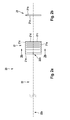
- Fig. 1a and 1b show an electrode member 10 according to a first embodiment with an electrode 11 and a lead 12 and a section through the electrode 11.
- the lead 12 consists of a rope of solid or stranded wire strands or - fibers of the type cited above.
- the distal end of the rope forms the electrode 11, in this embodiment, the wire along a central longitudinal axis 13 is helically wound or wound.
- the supply line 12 is in extension of this longitudinal axis 13 and may be either parallel to this or on this longitudinal axis.
- the electrode 11 is thus located immediately distal to the distal end 12b of the feed line 12.
- the electrode 11 further forms an outwardly (opposite to the longitudinal axis 13) facing electrically active electrode surface 11a, which is in an installed state with body medium and / or body tissue in contact. Due to the helical wound type, the rope forms gears 11b. As gear while a rotation of the wire around the longitudinal axis 13 around. At each additional turn another gear is formed.
- the aisles 11b are preferably adjacent directly following the distal or proximal preceding passage, but may also be designed differently, for example by a gap filled with insulating material between each gait 11b.
- the electrode surface 11 a is generally interrupted by a gap between each gear 11 b.
- FIGS Fig. 2a and 2b Another embodiment of the electrode element 20 is shown in FIGS Fig. 2a and 2b shown.
- the electrode 21 is not formed by helical winding or winding the rope, but by a meandering zig-zag forming consisting of rectilinear portions 21d, the opposite ends on the one hand with the distal preceding and on the other hand with the proximal subsequent rectilinear portion 21 d by opposite bent portions 21e are connected.
- a flat outwardly facing electrode surface 21a with two mutually perpendicular, imaginary outer edges 21c This arrangement also forms passageways 21b which extend through a rectilinear portion from a bent portion at one end to the bent portion at the other end of the rectilinear portion.
- the electrode 21 is in extension to the elongated lead 22 at its distal end 22b and is also formed by the distal end of the lead rope.
- this electrode element can be used, for example, in a so-called patch electrode line or else in an external sense electrode line which can be placed on the body.
- the planar, flat electrode 21 is tubular or cylindrical shaped along a longitudinal axis, wherein the elongate supply line 22 is located on or parallel to this longitudinal axis. This results in an easily manufactured configuration which can be used, for example, in an implantable electrode lead.
- individual, multiple or all gears 11b and 21b may be welded together, for example, by laser or resistance welding. This can be done, for example, alternately pairwise welding of gears 11b at circumferentially opposite locations, so as not to reduce the flexibility.
- Fig. 3 shows the portion of an implantable electrode lead 100 having an electrode element 10.
- the electrode element 10 is incorporated in an electrode lead body 110 so that the electrode 11 is isodiametric to the outer insulated surface 110a of the electrode lead body.
- the lead 12 extends to be electrically connected to a plug located and attached to the distal end of the electrode lead body.
- This plug corresponds to one of the standards IS-1, DF-1, IS-4, by means of which an electrical connection to an electrically active implant of the type mentioned above can be produced.
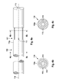
- the electrode lead body 110 is inserted into the Fig. 4a to 4c shown.
- the electrode lead body has at or near its distal, facing away from the plug End a recess 111 in the form of an annular groove, which has a radial depth which corresponds to the thickness of the rope and thus the electrode 11. That is, the diameter of the outward-facing electrically active surface 11a corresponds to the largest diameter of the electrode lead body 110 in its largest diameter position on the outer insulated surface, while the inner diameter of the electrode 11 corresponds to the outer diameter of the recess 111.
- first bore 112 In contact with the recess 111 is a first bore 112 with its distal end, wherein this bore extends parallel to the longitudinal axis 114 to the proximal end of the electrode line body 110.
- this bore 112 accommodates the feed line 12, which is led out of the bore of the electrode line body 110 into the recess 111 at its distal end 12b. Both the electrode 11 and the feed line 12 can be glued into the recess 111 or into the bore 112.
- an electrode lead body 110 additionally has a second bore 113, by means of which the implantable electrode lead 100 can be guided with the aid of a guide wire. This is usually on the longitudinal axis 114.
- the electrode may have the usual, known from the prior art active and passive fasteners.
- this can be multi-pole, that is to say designed with two or more electrodes.
- this for example, in a three-pole electrode line of the electrode line body 210 in the Fig. 5a to 5d have shown construction. He then points three in Fig. 4a to 4c described combinations of recesses 211a, 211b and 211 c, which are associated with each of these recesses in conjunction holes 212a, 212b and 212c. Each of these bores extends from a distal end located in or on the associated recesses along the longitudinal axis 214 of the electrode lead body 210 to the proximal end of the electrode lead body to which a known plug for electrical connection to an implant is attached.
- the bores 212a, 212b, and 212c are of different lengths. So that given necessary insulation with respect to the other leads 12, the holes are as in fig. 5b to 5d shown in the circumferential direction around the longitudinal axis 214 or around the bore 213 around advantageously distributed regularly. With this structure, implantable electrode leads with even more electrodes are possible.
Landscapes
- Health & Medical Sciences (AREA)
- Cardiology (AREA)
- Heart & Thoracic Surgery (AREA)
- Engineering & Computer Science (AREA)
- Biomedical Technology (AREA)
- Nuclear Medicine, Radiotherapy & Molecular Imaging (AREA)
- Radiology & Medical Imaging (AREA)
- Life Sciences & Earth Sciences (AREA)
- Animal Behavior & Ethology (AREA)
- General Health & Medical Sciences (AREA)
- Public Health (AREA)
- Veterinary Medicine (AREA)
- Electrotherapy Devices (AREA)
Applications Claiming Priority (1)
| Application Number | Priority Date | Filing Date | Title |
|---|---|---|---|
| DE102009002707A DE102009002707A1 (de) | 2009-04-29 | 2009-04-29 | Elektrodenelement, Elektrodenleitung mit einem Elektrodenelement und Herstellverfahren einer Elektrodenleitung |
Publications (1)
| Publication Number | Publication Date |
|---|---|
| EP2246092A1 true EP2246092A1 (fr) | 2010-11-03 |
Family
ID=42126058
Family Applications (1)
| Application Number | Title | Priority Date | Filing Date |
|---|---|---|---|
| EP10157044A Withdrawn EP2246092A1 (fr) | 2009-04-29 | 2010-03-19 | Procédé de fabrication d'une conduite d'électrode |
Country Status (3)
| Country | Link |
|---|---|
| US (1) | US20100280583A1 (fr) |
| EP (1) | EP2246092A1 (fr) |
| DE (1) | DE102009002707A1 (fr) |
Cited By (1)
| Publication number | Priority date | Publication date | Assignee | Title |
|---|---|---|---|---|
| EP3292885A1 (fr) * | 2016-09-06 | 2018-03-14 | BIOTRONIK SE & Co. KG | Système de conducteur d'électrode élastique et implant médical |
Citations (6)
| Publication number | Priority date | Publication date | Assignee | Title |
|---|---|---|---|---|
| US3788329A (en) * | 1972-04-17 | 1974-01-29 | Medtronic Inc | Body implantable lead |
| DE3530269A1 (de) * | 1985-08-22 | 1987-02-26 | Biotronik Mess & Therapieg | Implantierbare elektrode zur herzstimulation |
| EP0408358A2 (fr) * | 1989-07-14 | 1991-01-16 | Case Western Reserve University | Electrode intramusculaire pour système de stimulation neuromusculaire |
| DE19758368A1 (de) | 1997-12-29 | 1999-07-01 | Biotronik Mess & Therapieg | Defibrillationselektrodenanordnung |
| WO2000056399A1 (fr) * | 1999-03-23 | 2000-09-28 | Cardiac Pacemakers, Inc. | Electrode adaptable pour fils veineux coronaires |
| US7174220B1 (en) | 2004-03-16 | 2007-02-06 | Pacesetter, Inc. | Construction of a medical electrical lead |
Family Cites Families (5)
| Publication number | Priority date | Publication date | Assignee | Title |
|---|---|---|---|---|
| US4860769A (en) * | 1987-11-12 | 1989-08-29 | Thomas J. Fogarty | Implantable defibrillation electrode |
| US5397342A (en) * | 1993-06-07 | 1995-03-14 | Cardiac Pacemakers, Inc. | Resilient structurally coupled and electrically independent electrodes |
| DE19930268A1 (de) * | 1999-06-25 | 2001-01-04 | Biotronik Mess & Therapieg | Patch-Elektrode |
| DE102004048991B4 (de) * | 2004-10-04 | 2010-01-28 | Biotronik Crm Patent Ag | Elektrodenleitung |
| US7930038B2 (en) * | 2005-05-27 | 2011-04-19 | Cardiac Pacemakers, Inc. | Tubular lead electrodes and methods |
-
2009
- 2009-04-29 DE DE102009002707A patent/DE102009002707A1/de not_active Withdrawn
-
2010
- 2010-03-19 EP EP10157044A patent/EP2246092A1/fr not_active Withdrawn
- 2010-04-23 US US12/766,097 patent/US20100280583A1/en not_active Abandoned
Patent Citations (7)
| Publication number | Priority date | Publication date | Assignee | Title |
|---|---|---|---|---|
| US3788329A (en) * | 1972-04-17 | 1974-01-29 | Medtronic Inc | Body implantable lead |
| DE3530269A1 (de) * | 1985-08-22 | 1987-02-26 | Biotronik Mess & Therapieg | Implantierbare elektrode zur herzstimulation |
| EP0408358A2 (fr) * | 1989-07-14 | 1991-01-16 | Case Western Reserve University | Electrode intramusculaire pour système de stimulation neuromusculaire |
| DE19758368A1 (de) | 1997-12-29 | 1999-07-01 | Biotronik Mess & Therapieg | Defibrillationselektrodenanordnung |
| EP0927561A2 (fr) * | 1997-12-29 | 1999-07-07 | BIOTRONIK Mess- und Therapiegeräte GmbH & Co Ingenieurbüro Berlin | Système d'électrodes de défibrillation |
| WO2000056399A1 (fr) * | 1999-03-23 | 2000-09-28 | Cardiac Pacemakers, Inc. | Electrode adaptable pour fils veineux coronaires |
| US7174220B1 (en) | 2004-03-16 | 2007-02-06 | Pacesetter, Inc. | Construction of a medical electrical lead |
Cited By (1)
| Publication number | Priority date | Publication date | Assignee | Title |
|---|---|---|---|---|
| EP3292885A1 (fr) * | 2016-09-06 | 2018-03-14 | BIOTRONIK SE & Co. KG | Système de conducteur d'électrode élastique et implant médical |
Also Published As
| Publication number | Publication date |
|---|---|
| US20100280583A1 (en) | 2010-11-04 |
| DE102009002707A1 (de) | 2010-11-04 |
Similar Documents
| Publication | Publication Date | Title |
|---|---|---|
| DE60017716T2 (de) | Coextrudierte medizinische multilumenleitung | |
| DE69820418T2 (de) | Spulendrahtisolierung für biomedizinische leiter | |
| EP2711046B1 (fr) | Ligne d'électrodes et élément de raccordement pour implants électromédicaux | |
| DE60111222T2 (de) | Elektrisch isolierte leitung mit mehreren leitern | |
| DE19957241B4 (de) | Elektrische Leitung für medizinische Zwecke und System zur Einführung derselben | |
| DE602004005066T2 (de) | Implantierbare medizinische leitung und herstellungsverfahren | |
| DE112010001330T5 (de) | MRT-kompatible implantierbare Anschlusselektroden-Schnittstelle | |
| DE69704625T2 (de) | Elektrodenkabel zur elektrischen stimulation | |
| EP2110154B1 (fr) | Dispositif de réduction de l'occurrence de pannes pour implants allongés | |
| DE69801001T2 (de) | Medizinische elektrische leitung | |
| DE102009033767B4 (de) | Anschlusselement für Leitungswendel | |
| EP3630266B1 (fr) | Adaptateur électro-médical, électrode électro-médicale et émetteur d'impulsions électro-médical | |
| EP1285678B1 (fr) | Sonde à électrode unique pour système de stimulation cardiaque | |
| EP1955729A2 (fr) | Ligne d'électrodes et élément de raccord pour un stimulateur cardiaque implantable | |
| CH656313A5 (en) | Electrode with an electrical conductor which is connected to a contact provided for forming a connection with tissue | |
| EP2985053A1 (fr) | Ligne électrique implantable | |
| DE102009033770B4 (de) | Verbindung zwischen Stimulationselektrode und Leitungswendel | |
| EP2110156B1 (fr) | Elément de découplage de champs à utiliser avec une sonde implantable et appareil médical implantable | |
| DE102009033769B4 (de) | Crimp-Verbindung zwischen Stimulationselektrode und Leitungswendel | |
| EP2465569B1 (fr) | Appareil implantable | |
| EP2246092A1 (fr) | Procédé de fabrication d'une conduite d'électrode | |
| DE3304506A1 (de) | Elektrodenstecker fuer herzschrittmacher-elektrode | |
| EP2478933A2 (fr) | Appareil implantable | |
| EP0306442B1 (fr) | Electrode implantable de stimulation cardiaque | |
| EP2283894B1 (fr) | Conduite d'électrodes de stimulation |
Legal Events
| Date | Code | Title | Description |
|---|---|---|---|
| PUAI | Public reference made under article 153(3) epc to a published international application that has entered the european phase |
Free format text: ORIGINAL CODE: 0009012 |
|
| AK | Designated contracting states |
Kind code of ref document: A1 Designated state(s): AT BE BG CH CY CZ DE DK EE ES FI FR GB GR HR HU IE IS IT LI LT LU LV MC MK MT NL NO PL PT RO SE SI SK SM TR |
|
| AX | Request for extension of the european patent |
Extension state: AL BA ME RS |
|
| 17P | Request for examination filed |
Effective date: 20110502 |
|
| 17Q | First examination report despatched |
Effective date: 20170320 |
|
| STAA | Information on the status of an ep patent application or granted ep patent |
Free format text: STATUS: THE APPLICATION IS DEEMED TO BE WITHDRAWN |
|
| 18D | Application deemed to be withdrawn |
Effective date: 20171003 |