EP2246152B1 - Ensemble de biseautage des coins de feuilles de verre - Google Patents
Ensemble de biseautage des coins de feuilles de verre Download PDFInfo
- Publication number
- EP2246152B1 EP2246152B1 EP10161368.5A EP10161368A EP2246152B1 EP 2246152 B1 EP2246152 B1 EP 2246152B1 EP 10161368 A EP10161368 A EP 10161368A EP 2246152 B1 EP2246152 B1 EP 2246152B1
- Authority
- EP
- European Patent Office
- Prior art keywords
- slide
- assembly
- sheet
- locator
- respect
- Prior art date
- Legal status (The legal status is an assumption and is not a legal conclusion. Google has not performed a legal analysis and makes no representation as to the accuracy of the status listed.)
- Active
Links
Images


Classifications
-
- B—PERFORMING OPERATIONS; TRANSPORTING
- B24—GRINDING; POLISHING
- B24B—MACHINES, DEVICES, OR PROCESSES FOR GRINDING OR POLISHING; DRESSING OR CONDITIONING OF ABRADING SURFACES; FEEDING OF GRINDING, POLISHING, OR LAPPING AGENTS
- B24B9/00—Machines or devices designed for grinding edges or bevels on work or for removing burrs; Accessories therefor
- B24B9/02—Machines or devices designed for grinding edges or bevels on work or for removing burrs; Accessories therefor characterised by a special design with respect to properties of materials specific to articles to be ground
- B24B9/06—Machines or devices designed for grinding edges or bevels on work or for removing burrs; Accessories therefor characterised by a special design with respect to properties of materials specific to articles to be ground of non-metallic inorganic material, e.g. stone, ceramics, porcelain
- B24B9/08—Machines or devices designed for grinding edges or bevels on work or for removing burrs; Accessories therefor characterised by a special design with respect to properties of materials specific to articles to be ground of non-metallic inorganic material, e.g. stone, ceramics, porcelain of glass
- B24B9/10—Machines or devices designed for grinding edges or bevels on work or for removing burrs; Accessories therefor characterised by a special design with respect to properties of materials specific to articles to be ground of non-metallic inorganic material, e.g. stone, ceramics, porcelain of glass of plate glass
-
- B—PERFORMING OPERATIONS; TRANSPORTING
- B24—GRINDING; POLISHING
- B24B—MACHINES, DEVICES, OR PROCESSES FOR GRINDING OR POLISHING; DRESSING OR CONDITIONING OF ABRADING SURFACES; FEEDING OF GRINDING, POLISHING, OR LAPPING AGENTS
- B24B47/00—Drives or gearings; Equipment therefor
- B24B47/22—Equipment for exact control of the position of the grinding tool or work at the start of the grinding operation
-
- B—PERFORMING OPERATIONS; TRANSPORTING
- B24—GRINDING; POLISHING
- B24B—MACHINES, DEVICES, OR PROCESSES FOR GRINDING OR POLISHING; DRESSING OR CONDITIONING OF ABRADING SURFACES; FEEDING OF GRINDING, POLISHING, OR LAPPING AGENTS
- B24B49/00—Measuring or gauging equipment for controlling the feed movement of the grinding tool or work; Arrangements of indicating or measuring equipment, e.g. for indicating the start of the grinding operation
- B24B49/02—Measuring or gauging equipment for controlling the feed movement of the grinding tool or work; Arrangements of indicating or measuring equipment, e.g. for indicating the start of the grinding operation according to the instantaneous size and required size of the workpiece acted upon, the measuring or gauging being continuous or intermittent
Definitions
- the present invention relates to a corner bevelling assembly for bevelling corners of glass sheets (see EP-A-1 769 885 , for example).
- two-sided grinding machines which comprise a succession of grinding wheels for grinding the opposite lateral surfaces of the sheet; and two corner bevelling assemblies, downstream from the grinding wheels in the travelling direction of the sheet, for grinding the front and rear corners of the sheet.
- Each corner bevelling assembly comprises a vertical-axis grinding wheel; a first powered guide-slide assembly for moving the grinding wheel in a longitudinal direction parallel to the travelling direction of the sheet; and a second powered guide-slide assembly for moving the grinding wheel to and from a forward work position in a transverse direction perpendicular to the longitudinal direction.
- the sheet is fed longitudinally towards the corner bevelling assembly at a given speed; as the sheet moves forward, the grinding wheel is moved in the transverse direction towards the sheet and into a given forward work position by the second guide-slide assembly; and, once the position of the sheet is determined, the first guide-slide assembly eases the grinding wheel towards the sheet in the longitudinal direction, to minimize impact between the sheet and the grinding wheel waiting in the forward work position.
- the above is mainly due to wear of the sheet conveyors and/or errors in detecting the position of the sheet making it difficult to determine the exact position of the sheet on the conveyor, close to the corner bevelling assembly.
- a corner bevelling assembly for bevelling corners of glass sheets, the assembly comprising a fixed frame; a movable frame; a grinding wheel; a supporting arm for supporting said grinding wheel and connected to said movable frame; and an actuating device interposed between said fixed frame and said movable frame, and in turn comprising a first powered guide-slide assembly for moving the movable frame in a direction parallel to a longitudinal travelling direction of a work sheet of glass, and a second powered guide-slide assembly for moving said movable frame and said supporting arm with respect to the fixed frame in a transverse direction perpendicular to said longitudinal direction; the assembly being characterized by also comprising a reference locator which, in use, is positioned against a longitudinal lateral surface, parallel to said longitudinal direction, of said sheet; relative-motion means for enabling movement, parallel to said transverse direction, of said reference locator with respect to said supporting arm; detecting means for detecting the position of said reference locator with respect to the supporting arm;
- the present invention also relates to a grinding method for bevelling corners of glass sheets.
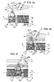
- Number 1 in Figure 1 indicates as a whole a system for grinding glass sheets, and which comprises a known powered line conveyor 2 (not described in detail) for feeding a work sheet 3 in a longitudinal travelling direction 4 ( Figures 1 and 3a-3f ); a known two-sided grinding machine 5 (shown partly) for grinding the longitudinal lateral surfaces of sheet 3; and a corner bevelling assembly 7 for bevelling the front and rear corners of sheet 3.
- a known powered line conveyor 2 (not described in detail) for feeding a work sheet 3 in a longitudinal travelling direction 4 ( Figures 1 and 3a-3f ); a known two-sided grinding machine 5 (shown partly) for grinding the longitudinal lateral surfaces of sheet 3; and a corner bevelling assembly 7 for bevelling the front and rear corners of sheet 3.
- Assembly 7 comprises a fixed frame 8; and two perpendicular powered guide-slide assemblies 9 and 10.
- Assembly 9 comprises a straight guide 11 fitted integrally to frame 8; and a slide 12 fitted to guide 11 to slide back and forth in a direction 11a parallel to longitudinal direction 4 and under the control of a respective actuator 12a, preferably an electric motor.
- Slide 12 is fitted integrally with a straight guide 13 of assembly 10, the slide 14 of which slides back and forth along guide 13 in a transverse direction 13a, perpendicular to directions 4 and 11a, and under the control of a respective actuator 14a, preferably an electric motor.
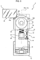
- An inverted-T-shaped supporting body 15 extends upwards from slide 14, is hinged to slide 14 in known manner to rotate about a hinge axis parallel to direction 11a, and is fitted with a mounting plate or frame 16.
- Plate 16 is fitted to a fixed guide 18, fitted to a vertical wall 19 of body 15, to slide up and down in a vertical direction 18a perpendicular to directions 11a and 13a, and under the control of a screw-nut screw assembly 20 operated by a knob 21.
- assembly 7 also comprises a grinding wheel arm 22 projecting from and connected to mounting plate 16 by a guide-slide assembly 23 ( Figure 2 ).
- Assembly 23 comprises two straight guides 24 fitted integrally to mounting plate 16 and parallel to directions 4 and 11a; and a slide 25 fitted to guides 24 to slide back and forth, and fitted firmly with a rear connecting portion of arm 22.
- arm 22 At its free end opposite the rear connecting portion, arm 22 is fitted with a powered grinding wheel 27 fitted to arm 22 to rotate about a vertical axis 27a, perpendicular to directions 4, 11a and 13a, under the control of a respective electric motor.
- arm 22 On the opposite side of grinding wheel 27 to slide 25, arm 22 is fitted integrally, in a fixed position with respect to grinding wheel 27, with a locator 28 for arresting the front and rear lateral surfaces 3a, 3b of sheet 3 perpendicular to longitudinal direction 4.
- locator 28 is bounded longitudinally by two opposite flat surfaces 28a, 28b parallel to each other and perpendicular to longitudinal direction 4.
- Each surface 28a, 28b is located at a distance from grinding wheel 27, and is designed and positioned to lie in a plane parallel to axis 27a of grinding wheel 27, perpendicular to direction 4, and intersecting grinding wheel 27, so as to define a stop for part of the front lateral surface 3a or rear lateral surface 3b of work sheet 3.
- locator 28 is defined by at least one cylindrical body with a generating line parallel to axis 27a of grinding wheel 27, but still at a distance from grinding wheel 27.
- a flexible compensating device 30 is interposed between arm 22 and mounting plate 16, to move arm 22 longitudinally with respect to plate 16, and so permit, in use, controlled movement of arm 22, and therefore of locator 28, with respect to plate 16 by the thrust exerted by sheet 3 on either one of surfaces 28a and 28b of locator 28.
- device 30 comprises a double-acting pneumatic linear actuator 31, which in turn comprises an outer casing 32 fitted integrally to mounting plate 16 by a platelike body 33 of screw-nut screw assembly 20; and two opposite output rods 35 having opposite end portions, each connected to a respective arm 36 of a top fork 37 of arm 22.
- Platelike body 33 of screw-nut screw assembly 20 is also fitted firmly with an outer casing 38 of a linear position transducer 39, a movable output member 40 of which is connected to one of arms 36.
- Transducer 39 is connected electrically to a known comparing and control unit 42, to which actuators 12a and 14a of guide-slide assemblies 9 and 10 are also connected.
- device 30 also comprises two opposite stop decelerators 44 for limiting the movement of arm 22 to two limit positions. More specifically, the two decelerators have respective casings 45 fitted integrally to arm 22; and respective sliding members 46 on opposite sides of a reference appendix 47 integral with plate 16 and projecting from plate 16 through a longitudinal opening 48 formed through slide 25.
- actuator 12a is operated to move inverted-T-shaped supporting body 15 in the same travelling direction as sheet 3, but at a slower speed, so as to gradually reduce the relative speed and therefore the distance between locator 28 and sheet 3.
- Linear actuator 31 continues to be powered, but at a lower pressure than for the fast movement of arm 22 towards sheet 3, and which varies according to the size of sheet 3, as explained below.
- actuator 14a is operated to ease grinding wheel 27 towards the sheet and grind the front corner, as shown in Figure 3b .
- actuator 12a is operated to withdraw grinding wheel 27 from sheet 3, followed by operation of actuator 14a to move grinding wheel 27 back to the start position ( Figure 3c ).
- actuator 12a is operated again to move grinding wheel 27 to the rear of sheet 3, and actuator 14a is operated to move the grinding wheel back into the forward intercept position ( Figure 3d ).
- actuator 31 is operated to move arm 22, with respect to plate 16, towards sheet 3, and actuator 12a is operated to move plate 16 and arm 22 towards sheet 3, travelling ahead of the arm, at a faster speed than that of sheet 3.
- the feed pressure of actuator 31 is adjusted, so that it acts as an air spring, in exactly the same way as for the front corner.
- unit 42 controls the movement of actuator 12a as described above ( Figure 3e ).
- actuator 14a is operated to move grinding wheel 27 onto sheet 3 and grind the rear corner. At this point, the grinding wheel is withdrawn from sheet 3 into the start position, waiting for the front corner of the next work sheet 3.
- locator 28 is movable with respect to arm 22. More specifically, locator 28 is fitted to a guide-slide assembly 50 comprising a guide 53 connected integrally to arm 22, and a slide 49 fitted to guide 53 to slide in a direction 49a parallel to direction 13a, and is connected integrally to a front end portion of slide 49.
- An adjustable stop device 54 is interposed between arm 22 and slide 49 to determine the position of slide 49 with respect to arm 22, and which comprises a screw 55 screwed to a nut screw integral with arm 22; and a stop shoulder 56 carried by slide 49 and which cooperates with the end of screw 55.
- Shoulder 56 is associated with an electric switch 57 connected electrically to unit 42 to supply unit 42 with a signal to stop actuator 14a when the end of screw 55 rests against shoulder 56, i.e. when the slide is in the withdrawn limit position.
- two lateral reference locators 50a, 50b are fitted firmly or in rotary manner to slide 49, are aligned in a direction parallel to longitudinal direction 4, and extend perpendicular to sheet 3 and directions 4, 11a and 13a to cooperate, in use, with a longitudinal lateral surface 3c of sheet 3 parallel to the longitudinal direction.
- Slide 49 is moved into a forward limit position by a linear actuator 52, which, in the example shown, is a mechanical actuator comprising a variably preloaded spring.
- actuator 52 is pneumatic or electromechanical, both controlled by respective control units (not shown) connected to unit 42.
- stop device 54 is replaced by a position transducer 58 for determining the position of slide 49 with respect to arm 22 in direction 49a, and for sending a corresponding position signal to unit 42.
- sheet 3 travels in longitudinal direction 4 until it comes to rest against locator 28, as described above; in which situation, lateral locators 50a, 50b are detached from longitudinal lateral surface 3c of sheet 3, so as not to interfere with sheet 3.
- slide 49 moves towards sheet 3 in direction 13a to grind the corner, slide 49, pushed by actuator 52 into the forward position, moves integrally with arm 22 until one of locators 50a, 50b contacts longitudinal lateral surface 3c of sheet 3.
- slide 49 starts moving with respect to arm 22, and grinding of the corner commences. Grinding is terminated when shoulder 56 contacts screw 55, and switch 57 sends a stop signal to unit 42 to stop actuator 14a.
- Positioning sheet 3 against locators 50a, 50b provides for positioning the sheet correctly with respect to the grinding wheel and so ensuring consistent grinding and dimensional consistency of the ground corner.
- transducer 58 begins determining the movement of slide 49 with respect to arm 22, and sends a movement signal to unit 42, which comprises a comparing block 42a for comparing the movement signal with a reference signal stored in unit 42, for stopping actuator 14a, and therefore grinding of the corner, when the signal from transducer 58 equals the reference signal.
- assembly 7 described provides above all for preventing any direct contact between the moving sheet 3 and grinding wheel 27.
- the sheet 3 on conveyor 2 nears grinding wheel 27, it comes to rest against locator 28, which keeps it at a distance from grinding wheel 27, thus reducing, or even completely eliminating, the risk of chipping or breaking the sheet, and/or uneven wear of grinding wheel 27 caused mainly by a moving element, such as the sheet, contacting a fast-rotating member, such as the grinding wheel.
- the locator 28 and compensating device 30 combination provides not only for smooth, steady sheet-locator contact, but also for accurately controlling sheet-locator contact pressure, so that it is minimum or at any rate always below a predetermined threshold, regardless of the size, and therefore weight, of the sheet.
- Locators 50a, 50b associated with the stop device or transducer provide for moving the grinding wheel in direction 13a with respect to longitudinal lateral surface 3c by the same amount at all times, thus ensuring consistent grinding of the corner, regardless of any dimensional or positioning errors of sheet 3 in transverse direction 13a.
- sheet 3 When grinding the corner, sheet 3 is maintained in sliding contact with locator 28 and in contact with locators 50a, 50b at all times, which means the sheet is ground in the same conditions as if the sheet were stationary inside a grinding station, into which the grinding wheel is moved.
- assembly 7 may obviously have no locator 28; in which case, the position of sheet 3 in longitudinal direction 4 may be determined by detecting devices located, for example, along the route of the sheet. Moreover, locator 28 may be fitted to slide 49, as opposed to arm 22.
Landscapes
- Engineering & Computer Science (AREA)
- Mechanical Engineering (AREA)
- Chemical & Material Sciences (AREA)
- Ceramic Engineering (AREA)
- Inorganic Chemistry (AREA)
- Grinding And Polishing Of Tertiary Curved Surfaces And Surfaces With Complex Shapes (AREA)
- Nitrogen Condensed Heterocyclic Rings (AREA)
Claims (10)
- Assemblage de biseautage de coins (7) pour biseauter les angles de feuilles de verre (3), cet assemblage comportant un cadre fixe (8); un cadre mobile (16) ; une roue de meulage (27) ; un bras de support (22) pour porter ladite roue de meulage (27) et couplé audit cadre mobile (16) ; ainsi qu'un dispositif d'actionnement (9, 10) interposé entre ledit cadre fixe (8) et ledit cadre mobile (16) ; et comprenant en fait un premier ensemble motorisé de guidage et de coulissement (9) pour déplacer le cadre mobile (16) dans une direction (11a) parallèle à la direction longitudinale de cheminement (4) de la feuille de verre en travail (3), et un second ensemble de guidage et de coulissement (10) pour déplacer le cadre mobile (16) et ledit bras de support (22), par rapport au cadre fixe (8), dans une direction transversale (13a) perpendiculaire à ladite direction longitudinale de cheminement (4) ; l'assemblage étant caractérisé en ce qu'il comporte également un positionneur de référence (50a, 50b) qui, en cours d'utilisation, est positionné contre ladite surface longitudinale latérale (4) de ladite feuille (3) ; des moyens de déplacement relatifs (50) pour assurer le déplacement dudit positionneur de référence (50a, 50b) par rapport audit bras de support (22) ; des moyens de détection (54) (58) pour détecter la position dudit positionneur de référence (50a, 50b) par rapport audit bras de support (22) et des moyens de commande (42) pour commander ledit second ensemble de guidage et de coulissement (10) en fonction de la position dudit positionneur de référence (50a, 50b).
- Assemblage selon la revendication 1, caractérisé en ce que ledit positionneur de référence (50a, 50b) est mobile par rapport audit bras de support (22) entre deux positions d'arrêt limites.
- Assemblage selon les revendications 1 ou 2, caractérisé en ce qu'il comporte un coulisseau (49) fixé audit bras de support (22) pour coulisser vers l'arrière et vers l'avant dans une direction (49a) parallèle à ladite direction transversale (13a) ; et des moyens flexibles élastiques (52) interposés entre ledit coulisseau (49) et ledit bras de support (22) pour maintenir le coulisseau (49) dans une première position limite avant contre ladite direction longitudinale ; ledit positionneur de référence (50a, 50b) étant porté par ledit coulisseau (49).
- Assemblage selon la revendication 3, caractérisé en ce que lesdits moyens de détection comportent des moyens d'arrêt ajustables (54) interposés entre ledit coulisseau (49) et ledit bras de support (22) pour arrêter ledit coulisseau (49) dans une seconde position limite de retrait, opposée à ladite première position limite avant ; des moyens d'immobilisation (57) pour immobiliser ledit second ensemble de guidage et de coulissement (10) lorsque ledit coulisseau (49) se trouve dans ladite seconde position limite de retrait.
- Assemblage selon la revendication 3, caractérisé en ce que lesdits moyens de détection comportent des moyens de transduction (58) pour déterminer la position dudit coulisseau (49) par rapport audit bras de support (42) pour comparer un signal issu des moyens de transduction (58) avec un signal de référence ; des moyens d'immobilisation (42) agencés pour immobiliser ledit second ensemble de guidage et de coulissement (10) lorsque le signal desdits moyens de transduction (58) sont égaux audit signal de référence.
- Assemblage selon l'une quelconque des revendications 3 à 5, caractérisé en ce que ledit coulisseau (49) est également lié à un autre positionneur (50b) définissant un arrêt pour une surface latérale frontale ou arrière, parallèle à ladite direction transversale (13a) de ladite feuille (3).
- Procédé de meulage pour biseauter les angles de feuilles de verre (3) au moyen d'un assemblage de biseautage des angles (7) selon la revendication 1 et comportant les étapes d'amenée d'une feuille de verre à travailler (3) dans une direction longitudinale (4) et le meulage des angles au moyen d'une roue de meulage (27) ; ce procédé étant caractérisé par le déplacement d'un positionneur de référence (50a, 50b) en contact avec une surface longitudinale latérale (36) ; parallèle à ladite surface longitudinale latérale (4) ; autorisant un déplacement dudit positionneur de référence (50a, 50b) par rapport audit bras de support (22) dans la direction (49a) parallèle à ladite direction transversale (13a) ; déterminant la position dudit positionneur de référence (50a, 50b) par rapport audit bras de support (22) et commandant ledit second ensemble de guidage et de coulissement (10) en fonction de la position dudit positionneur de référence (50a, 50b).
- Procédé selon la revendication 7, caractérisé en ce que ladite position dudit positionneur de référence (50a, 50b) par rapport audit bras de support (22) est déterminée en déplaçant ledit positionneur de référence (50a, 50b) dans une première position limite avant vers ladite direction de cheminement longitudinal (4) ; et en autorisant ledit positionneur de référence (50a, 50b) à retourner vers une seconde position limite de retrait opposée à ladite première position limite avant ; ledit second ensemble de guidage et de coulissement (10) étant immobilisé lorsque ledit positionneur de référence se trouve dans ladite seconde position de retrait.
- Procédé selon la revendication 7, caractérisé en ce que la position dudit positionneur de référence (50a, 50b) est déterminée en déplaçant ledit positionneur de référence dans une première position limite avant vers ladite direction de cheminement longitudinal (4) et en autorisant le positionneur de référence à retourner vers une seconde position limite de retrait opposée à ladite première limite de retrait ; en immobilisant ledit second ensemble de guidage et de coulissement (10), comprenant les étapes de détermination de la position du positionneur de référence par rapport audit bras de support (22) ; de comparaison de la position déterminée dudit positionneur de référence avec une position de référence ; et d'arrêt dudit second ensemble de guidage et de coulissement (10) lorsque la position déterminée correspond à la position de référence.
- Procédé selon l'une quelconque des revendications 7 à 9, caractérisé en ce que ledit angle est meulé avec ladite roue de meulage dans une position fixe, dans ladite direction longitudinale (4) ; par rapport à ladite roue de meulage (27) ; et en déplaçant sensiblement ladite roue de meulage dans ladite direction transversale (13a) vers ladite feuille (3).
Applications Claiming Priority (1)
| Application Number | Priority Date | Filing Date | Title |
|---|---|---|---|
| ITTO2009A000342A IT1393877B1 (it) | 2009-04-29 | 2009-04-29 | Gruppo rompispigolo per lo smusso di spigoli di lastre di vetro |
Publications (2)
| Publication Number | Publication Date |
|---|---|
| EP2246152A1 EP2246152A1 (fr) | 2010-11-03 |
| EP2246152B1 true EP2246152B1 (fr) | 2013-04-24 |
Family
ID=41258213
Family Applications (1)
| Application Number | Title | Priority Date | Filing Date |
|---|---|---|---|
| EP10161368.5A Active EP2246152B1 (fr) | 2009-04-29 | 2010-04-28 | Ensemble de biseautage des coins de feuilles de verre |
Country Status (3)
| Country | Link |
|---|---|
| US (1) | US8414358B2 (fr) |
| EP (1) | EP2246152B1 (fr) |
| IT (1) | IT1393877B1 (fr) |
Families Citing this family (3)
| Publication number | Priority date | Publication date | Assignee | Title |
|---|---|---|---|---|
| DE102014213953A1 (de) * | 2014-07-17 | 2016-01-21 | Schott Ag | Verfahren zur hochpräzisen Eckenkonturierung von Flachglassubstraten im Durchlauf |
| IT201900002925A1 (it) * | 2019-02-28 | 2020-08-28 | Bottero Spa | Metodo e gruppo di molatura e lucidatura di uno spigolo di una lastra di vetro |
| CN109877662B (zh) * | 2019-04-22 | 2023-07-14 | 海盐齐家五金弹簧厂 | 一种弹簧生产用端面加工装置 |
Family Cites Families (18)
| Publication number | Priority date | Publication date | Assignee | Title |
|---|---|---|---|---|
| IT1023816B (it) * | 1973-12-26 | 1978-05-30 | Intercontinental Trading Co | Dispositivo per lavorare gli angoli di una lastra per cristalli e specchi |
| DK14583A (da) * | 1982-01-20 | 1983-07-21 | Saint Gobain Vitrage | Fremgangsmaade og apparat til positionsstyring af vaerktoejet paa en kantbearbejdningsmaskine til glasplader |
| JPS6165762A (ja) * | 1984-09-06 | 1986-04-04 | Nippon Sheet Glass Co Ltd | 板状体の端面研磨装置 |
| US4739590A (en) * | 1985-06-11 | 1988-04-26 | Acc Automation, Inc. | Method for seaming glass |
| IT1190474B (it) * | 1986-02-04 | 1988-02-16 | Siv Soc Italiana Vetro | Macchina perfezionata per la molatura del bordo di lastre di vetro,particolarmente vetrature per automobili |
| IT1229286B (it) * | 1989-04-19 | 1991-08-08 | Luigi Bovone | Metodo ed apparecchio per bisellare angoli interni di lastre di vetro, a cristallo o semicristallo, colorate o meno, e prodotto ottenuto. |
| IT1262263B (it) * | 1993-12-30 | 1996-06-19 | Delle Vedove Levigatrici Spa | Procedimento di levigatura per profili curvi e sagomati e macchina levigatrice che realizza tale procedimento |
| US5713784A (en) * | 1996-05-17 | 1998-02-03 | Mark A. Miller | Apparatus for grinding edges of a glass sheet |
| AT408856B (de) * | 1997-12-02 | 2002-03-25 | Lisec Peter | Vorrichtung zum automatischen säumen von plattenförmigen gegenständen |
| US6325704B1 (en) * | 1999-06-14 | 2001-12-04 | Corning Incorporated | Method for finishing edges of glass sheets |
| US6855030B2 (en) * | 1999-10-27 | 2005-02-15 | Strasbaugh | Modular method for chemical mechanical planarization |
| IT1318182B1 (it) * | 2000-07-17 | 2003-07-23 | Bavelloni Z Spa | Gruppo spigolatore applicabile a macchine per la lavorazione dei bordi di lastre in genere ed in particolare di lastre di vetro. |
| IT1318885B1 (it) * | 2000-09-20 | 2003-09-10 | Bavelloni Z Spa | Gruppo spigolatore per macchine per la lavorazione dei bordi di lastre in genere ed in particolare di lastre di vetro. |
| ITMI20012445A1 (it) * | 2001-11-20 | 2003-05-20 | Bovone Internat Holding S A | Macchina per raggiare gli spigoli di lastre di vetro |
| ITTO20021010A1 (it) * | 2002-11-20 | 2004-05-21 | Biesse Spa | Metodo per il controllo della posizione operativa di una mola utilizzata su di una macchina per la lavorazione di bordi di lastre di vetro, marmo e simili materiali lapidei, e macchina per l'implementazione di tale metodo |
| ITTV20030091A1 (it) * | 2003-06-20 | 2004-12-21 | For El Base Di Davanzo Nadia & C S Nc | Macchina automatica per la smerigliatura dei bordi delle lastre di vetro e procedimento automatico per la smerigliatura dei bordi delle lastre di vetro. |
| US7001249B1 (en) * | 2005-01-11 | 2006-02-21 | Guardian Industries, Inc. | Methods and systems for finishing edges of glass sheets |
| ITTV20050145A1 (it) * | 2005-10-03 | 2007-04-04 | For El Base Di Vianello Fortuna | Macchina automatica per la smerigliatura e la molatura dei bordi delle lastre di vetro |
-
2009
- 2009-04-29 IT ITTO2009A000342A patent/IT1393877B1/it active
-
2010
- 2010-04-28 US US12/769,005 patent/US8414358B2/en not_active Expired - Fee Related
- 2010-04-28 EP EP10161368.5A patent/EP2246152B1/fr active Active
Also Published As
| Publication number | Publication date |
|---|---|
| EP2246152A1 (fr) | 2010-11-03 |
| ITTO20090342A1 (it) | 2010-10-30 |
| IT1393877B1 (it) | 2012-05-11 |
| US8414358B2 (en) | 2013-04-09 |
| US20100279588A1 (en) | 2010-11-04 |
Similar Documents
| Publication | Publication Date | Title |
|---|---|---|
| EP2246152B1 (fr) | Ensemble de biseautage des coins de feuilles de verre | |
| EP2246151B1 (fr) | Ensemble de meulage pour biseauter les coins de feuilles de verre | |
| CN104162817B (zh) | 分体式智能磨床 | |
| US4976766A (en) | Device for positioning heated glass sheets without deformation | |
| EP2845840B1 (fr) | Machine et procédé pour effectuer des opérations de découpe sur des feuilles de verre laminées | |
| CN104400537A (zh) | 自动送料装置 | |
| EP3313612B1 (fr) | Machine de meulage pour éléments en forme de plaque, en particulier des tuiles et des plaques en céramique, des pierres naturelles, du verre, ou similaires | |
| CN109702805B (zh) | 一种自动侧向扶棉同步运行装置 | |
| CN104084966A (zh) | 一种快速切管器 | |
| CN106217145A (zh) | 一种美工刀磨床 | |
| EP0539512A4 (en) | Device for positioning hot glass sheets | |
| EP2687328B1 (fr) | Machine à rectifier pour panneaux en bois ou similairs | |
| CN203993404U (zh) | 分体式智能磨床 | |
| US10035204B2 (en) | Saw blade indexing assembly | |
| EP2001275A1 (fr) | Appareil et procédé de séparation de composants électroniques | |
| CN210997923U (zh) | 一种磨头进给和缓冲装置 | |
| CN203592367U (zh) | 磨边机磨轮进给检测装置 | |
| CN201036845Y (zh) | 刀尖圆弧刃磨机的测控装置 | |
| CN203592368U (zh) | 卧式四边磨边机 | |
| KR101490384B1 (ko) | 솔레노이드 밸브 응답 속도 측정 장치 및 방법 | |
| CN203592398U (zh) | 磨边机磨轮进给旋转装置 | |
| CN104416459A (zh) | 磨边机磨轮进给装置 | |
| CN221474591U (zh) | 玻璃磨边抛光装置 | |
| KR102493566B1 (ko) | 택배 물건 컨베이어 시스템 및 이를 이용한 택배 물건 배송방법 | |
| CN219987731U (zh) | 一种航空轮胎带束层裁断装置 |
Legal Events
| Date | Code | Title | Description |
|---|---|---|---|
| PUAI | Public reference made under article 153(3) epc to a published international application that has entered the european phase |
Free format text: ORIGINAL CODE: 0009012 |
|
| AK | Designated contracting states |
Kind code of ref document: A1 Designated state(s): AT BE BG CH CY CZ DE DK EE ES FI FR GB GR HR HU IE IS IT LI LT LU LV MC MK MT NL NO PL PT RO SE SI SK SM TR |
|
| AX | Request for extension of the european patent |
Extension state: AL BA ME RS |
|
| 17P | Request for examination filed |
Effective date: 20110503 |
|
| GRAP | Despatch of communication of intention to grant a patent |
Free format text: ORIGINAL CODE: EPIDOSNIGR1 |
|
| GRAS | Grant fee paid |
Free format text: ORIGINAL CODE: EPIDOSNIGR3 |
|
| GRAA | (expected) grant |
Free format text: ORIGINAL CODE: 0009210 |
|
| AK | Designated contracting states |
Kind code of ref document: B1 Designated state(s): AT BE BG CH CY CZ DE DK EE ES FI FR GB GR HR HU IE IS IT LI LT LU LV MC MK MT NL NO PL PT RO SE SI SK SM TR |
|
| REG | Reference to a national code |
Ref country code: GB Ref legal event code: FG4D |
|
| REG | Reference to a national code |
Ref country code: CH Ref legal event code: EP |
|
| REG | Reference to a national code |
Ref country code: AT Ref legal event code: REF Ref document number: 608299 Country of ref document: AT Kind code of ref document: T Effective date: 20130515 |
|
| REG | Reference to a national code |
Ref country code: IE Ref legal event code: FG4D |
|
| REG | Reference to a national code |
Ref country code: DE Ref legal event code: R096 Ref document number: 602010006492 Country of ref document: DE Effective date: 20130620 |
|
| REG | Reference to a national code |
Ref country code: AT Ref legal event code: MK05 Ref document number: 608299 Country of ref document: AT Kind code of ref document: T Effective date: 20130424 |
|
| REG | Reference to a national code |
Ref country code: LT Ref legal event code: MG4D |
|
| REG | Reference to a national code |
Ref country code: NL Ref legal event code: VDEP Effective date: 20130424 |
|
| PG25 | Lapsed in a contracting state [announced via postgrant information from national office to epo] |
Ref country code: AT Free format text: LAPSE BECAUSE OF FAILURE TO SUBMIT A TRANSLATION OF THE DESCRIPTION OR TO PAY THE FEE WITHIN THE PRESCRIBED TIME-LIMIT Effective date: 20130424 Ref country code: SI Free format text: LAPSE BECAUSE OF FAILURE TO SUBMIT A TRANSLATION OF THE DESCRIPTION OR TO PAY THE FEE WITHIN THE PRESCRIBED TIME-LIMIT Effective date: 20130424 Ref country code: PT Free format text: LAPSE BECAUSE OF FAILURE TO SUBMIT A TRANSLATION OF THE DESCRIPTION OR TO PAY THE FEE WITHIN THE PRESCRIBED TIME-LIMIT Effective date: 20130826 Ref country code: SE Free format text: LAPSE BECAUSE OF FAILURE TO SUBMIT A TRANSLATION OF THE DESCRIPTION OR TO PAY THE FEE WITHIN THE PRESCRIBED TIME-LIMIT Effective date: 20130424 Ref country code: NO Free format text: LAPSE BECAUSE OF FAILURE TO SUBMIT A TRANSLATION OF THE DESCRIPTION OR TO PAY THE FEE WITHIN THE PRESCRIBED TIME-LIMIT Effective date: 20130724 Ref country code: BE Free format text: LAPSE BECAUSE OF FAILURE TO SUBMIT A TRANSLATION OF THE DESCRIPTION OR TO PAY THE FEE WITHIN THE PRESCRIBED TIME-LIMIT Effective date: 20130424 Ref country code: IS Free format text: LAPSE BECAUSE OF FAILURE TO SUBMIT A TRANSLATION OF THE DESCRIPTION OR TO PAY THE FEE WITHIN THE PRESCRIBED TIME-LIMIT Effective date: 20130824 Ref country code: LT Free format text: LAPSE BECAUSE OF FAILURE TO SUBMIT A TRANSLATION OF THE DESCRIPTION OR TO PAY THE FEE WITHIN THE PRESCRIBED TIME-LIMIT Effective date: 20130424 Ref country code: FI Free format text: LAPSE BECAUSE OF FAILURE TO SUBMIT A TRANSLATION OF THE DESCRIPTION OR TO PAY THE FEE WITHIN THE PRESCRIBED TIME-LIMIT Effective date: 20130424 Ref country code: ES Free format text: LAPSE BECAUSE OF FAILURE TO SUBMIT A TRANSLATION OF THE DESCRIPTION OR TO PAY THE FEE WITHIN THE PRESCRIBED TIME-LIMIT Effective date: 20130804 Ref country code: GR Free format text: LAPSE BECAUSE OF FAILURE TO SUBMIT A TRANSLATION OF THE DESCRIPTION OR TO PAY THE FEE WITHIN THE PRESCRIBED TIME-LIMIT Effective date: 20130725 |
|
| PG25 | Lapsed in a contracting state [announced via postgrant information from national office to epo] |
Ref country code: PL Free format text: LAPSE BECAUSE OF FAILURE TO SUBMIT A TRANSLATION OF THE DESCRIPTION OR TO PAY THE FEE WITHIN THE PRESCRIBED TIME-LIMIT Effective date: 20130424 Ref country code: LV Free format text: LAPSE BECAUSE OF FAILURE TO SUBMIT A TRANSLATION OF THE DESCRIPTION OR TO PAY THE FEE WITHIN THE PRESCRIBED TIME-LIMIT Effective date: 20130424 Ref country code: BG Free format text: LAPSE BECAUSE OF FAILURE TO SUBMIT A TRANSLATION OF THE DESCRIPTION OR TO PAY THE FEE WITHIN THE PRESCRIBED TIME-LIMIT Effective date: 20130724 Ref country code: HR Free format text: LAPSE BECAUSE OF FAILURE TO SUBMIT A TRANSLATION OF THE DESCRIPTION OR TO PAY THE FEE WITHIN THE PRESCRIBED TIME-LIMIT Effective date: 20130424 Ref country code: CY Free format text: LAPSE BECAUSE OF FAILURE TO SUBMIT A TRANSLATION OF THE DESCRIPTION OR TO PAY THE FEE WITHIN THE PRESCRIBED TIME-LIMIT Effective date: 20130424 |
|
| REG | Reference to a national code |
Ref country code: IE Ref legal event code: MM4A |
|
| PG25 | Lapsed in a contracting state [announced via postgrant information from national office to epo] |
Ref country code: EE Free format text: LAPSE BECAUSE OF FAILURE TO SUBMIT A TRANSLATION OF THE DESCRIPTION OR TO PAY THE FEE WITHIN THE PRESCRIBED TIME-LIMIT Effective date: 20130424 Ref country code: CZ Free format text: LAPSE BECAUSE OF FAILURE TO SUBMIT A TRANSLATION OF THE DESCRIPTION OR TO PAY THE FEE WITHIN THE PRESCRIBED TIME-LIMIT Effective date: 20130424 Ref country code: SK Free format text: LAPSE BECAUSE OF FAILURE TO SUBMIT A TRANSLATION OF THE DESCRIPTION OR TO PAY THE FEE WITHIN THE PRESCRIBED TIME-LIMIT Effective date: 20130424 Ref country code: MC Free format text: LAPSE BECAUSE OF FAILURE TO SUBMIT A TRANSLATION OF THE DESCRIPTION OR TO PAY THE FEE WITHIN THE PRESCRIBED TIME-LIMIT Effective date: 20130424 Ref country code: DK Free format text: LAPSE BECAUSE OF FAILURE TO SUBMIT A TRANSLATION OF THE DESCRIPTION OR TO PAY THE FEE WITHIN THE PRESCRIBED TIME-LIMIT Effective date: 20130424 |
|
| PG25 | Lapsed in a contracting state [announced via postgrant information from national office to epo] |
Ref country code: IT Free format text: LAPSE BECAUSE OF FAILURE TO SUBMIT A TRANSLATION OF THE DESCRIPTION OR TO PAY THE FEE WITHIN THE PRESCRIBED TIME-LIMIT Effective date: 20130424 Ref country code: RO Free format text: LAPSE BECAUSE OF FAILURE TO SUBMIT A TRANSLATION OF THE DESCRIPTION OR TO PAY THE FEE WITHIN THE PRESCRIBED TIME-LIMIT Effective date: 20130424 Ref country code: NL Free format text: LAPSE BECAUSE OF FAILURE TO SUBMIT A TRANSLATION OF THE DESCRIPTION OR TO PAY THE FEE WITHIN THE PRESCRIBED TIME-LIMIT Effective date: 20130424 |
|
| PLBE | No opposition filed within time limit |
Free format text: ORIGINAL CODE: 0009261 |
|
| STAA | Information on the status of an ep patent application or granted ep patent |
Free format text: STATUS: NO OPPOSITION FILED WITHIN TIME LIMIT |
|
| 26N | No opposition filed |
Effective date: 20140127 |
|
| REG | Reference to a national code |
Ref country code: FR Ref legal event code: ST Effective date: 20140303 |
|
| PG25 | Lapsed in a contracting state [announced via postgrant information from national office to epo] |
Ref country code: IE Free format text: LAPSE BECAUSE OF NON-PAYMENT OF DUE FEES Effective date: 20130428 |
|
| REG | Reference to a national code |
Ref country code: DE Ref legal event code: R097 Ref document number: 602010006492 Country of ref document: DE Effective date: 20140127 |
|
| PG25 | Lapsed in a contracting state [announced via postgrant information from national office to epo] |
Ref country code: FR Free format text: LAPSE BECAUSE OF NON-PAYMENT OF DUE FEES Effective date: 20130624 |
|
| REG | Reference to a national code |
Ref country code: CH Ref legal event code: PL |
|
| GBPC | Gb: european patent ceased through non-payment of renewal fee |
Effective date: 20140428 |
|
| PG25 | Lapsed in a contracting state [announced via postgrant information from national office to epo] |
Ref country code: LI Free format text: LAPSE BECAUSE OF NON-PAYMENT OF DUE FEES Effective date: 20140430 Ref country code: CH Free format text: LAPSE BECAUSE OF NON-PAYMENT OF DUE FEES Effective date: 20140430 Ref country code: GB Free format text: LAPSE BECAUSE OF NON-PAYMENT OF DUE FEES Effective date: 20140428 |
|
| PG25 | Lapsed in a contracting state [announced via postgrant information from national office to epo] |
Ref country code: MT Free format text: LAPSE BECAUSE OF FAILURE TO SUBMIT A TRANSLATION OF THE DESCRIPTION OR TO PAY THE FEE WITHIN THE PRESCRIBED TIME-LIMIT Effective date: 20130424 |
|
| PG25 | Lapsed in a contracting state [announced via postgrant information from national office to epo] |
Ref country code: SM Free format text: LAPSE BECAUSE OF FAILURE TO SUBMIT A TRANSLATION OF THE DESCRIPTION OR TO PAY THE FEE WITHIN THE PRESCRIBED TIME-LIMIT Effective date: 20130424 |
|
| PG25 | Lapsed in a contracting state [announced via postgrant information from national office to epo] |
Ref country code: TR Free format text: LAPSE BECAUSE OF FAILURE TO SUBMIT A TRANSLATION OF THE DESCRIPTION OR TO PAY THE FEE WITHIN THE PRESCRIBED TIME-LIMIT Effective date: 20130424 |
|
| PG25 | Lapsed in a contracting state [announced via postgrant information from national office to epo] |
Ref country code: LU Free format text: LAPSE BECAUSE OF NON-PAYMENT OF DUE FEES Effective date: 20130428 Ref country code: MK Free format text: LAPSE BECAUSE OF FAILURE TO SUBMIT A TRANSLATION OF THE DESCRIPTION OR TO PAY THE FEE WITHIN THE PRESCRIBED TIME-LIMIT Effective date: 20130424 Ref country code: HU Free format text: LAPSE BECAUSE OF FAILURE TO SUBMIT A TRANSLATION OF THE DESCRIPTION OR TO PAY THE FEE WITHIN THE PRESCRIBED TIME-LIMIT; INVALID AB INITIO Effective date: 20100428 |
|
| REG | Reference to a national code |
Ref country code: DE Ref legal event code: R082 Ref document number: 602010006492 Country of ref document: DE Representative=s name: TERPATENT PARTGMBB, DE Ref country code: DE Ref legal event code: R082 Ref document number: 602010006492 Country of ref document: DE Representative=s name: TERPATENT PATENTANWAELTE TER SMITTEN EBERLEIN-, DE |
|
| PGFP | Annual fee paid to national office [announced via postgrant information from national office to epo] |
Ref country code: DE Payment date: 20250319 Year of fee payment: 16 |