EP2246155A2 - Adaptateur pour une clé à douille - Google Patents
Adaptateur pour une clé à douille Download PDFInfo
- Publication number
- EP2246155A2 EP2246155A2 EP10158578A EP10158578A EP2246155A2 EP 2246155 A2 EP2246155 A2 EP 2246155A2 EP 10158578 A EP10158578 A EP 10158578A EP 10158578 A EP10158578 A EP 10158578A EP 2246155 A2 EP2246155 A2 EP 2246155A2
- Authority
- EP
- European Patent Office
- Prior art keywords
- socket
- socket insert
- insert adapter
- adapter
- bolts
- Prior art date
- Legal status (The legal status is an assumption and is not a legal conclusion. Google has not performed a legal analysis and makes no representation as to the accuracy of the status listed.)
- Withdrawn
Links
Images





Classifications
-
- B—PERFORMING OPERATIONS; TRANSPORTING
- B25—HAND TOOLS; PORTABLE POWER-DRIVEN TOOLS; MANIPULATORS
- B25B—TOOLS OR BENCH DEVICES NOT OTHERWISE PROVIDED FOR, FOR FASTENING, CONNECTING, DISENGAGING, OR HOLDING
- B25B13/00—Spanners; Wrenches
- B25B13/10—Spanners; Wrenches with adjustable jaws
- B25B13/107—Spanners; Wrenches with adjustable jaws composed of a main body with exchangeable inserts
-
- B—PERFORMING OPERATIONS; TRANSPORTING
- B25—HAND TOOLS; PORTABLE POWER-DRIVEN TOOLS; MANIPULATORS
- B25B—TOOLS OR BENCH DEVICES NOT OTHERWISE PROVIDED FOR, FOR FASTENING, CONNECTING, DISENGAGING, OR HOLDING
- B25B13/00—Spanners; Wrenches
- B25B13/02—Spanners; Wrenches with rigid jaws
- B25B13/06—Spanners; Wrenches with rigid jaws of socket type
-
- B—PERFORMING OPERATIONS; TRANSPORTING
- B25—HAND TOOLS; PORTABLE POWER-DRIVEN TOOLS; MANIPULATORS
- B25B—TOOLS OR BENCH DEVICES NOT OTHERWISE PROVIDED FOR, FOR FASTENING, CONNECTING, DISENGAGING, OR HOLDING
- B25B13/00—Spanners; Wrenches
- B25B13/02—Spanners; Wrenches with rigid jaws
- B25B13/06—Spanners; Wrenches with rigid jaws of socket type
- B25B13/065—Spanners; Wrenches with rigid jaws of socket type characterised by the cross-section of the socket
-
- B—PERFORMING OPERATIONS; TRANSPORTING
- B25—HAND TOOLS; PORTABLE POWER-DRIVEN TOOLS; MANIPULATORS
- B25B—TOOLS OR BENCH DEVICES NOT OTHERWISE PROVIDED FOR, FOR FASTENING, CONNECTING, DISENGAGING, OR HOLDING
- B25B13/00—Spanners; Wrenches
- B25B13/56—Spanner sets
Definitions
- the present invention in general relates to a socket insert. More particularly, it relates to a hollow shape socket insert adapter used in conjunction with a socket driver for tightening, loosening, removing various sizes of nuts and bolts.
- Sockets are one of the most commonly used mechanical tools for driving nuts and bolts. Most of the earlier standard socket drivers were designed with specific metric or SAE size for fastening nuts/ bolts thus each time a different socket driver was required for driving nuts/ bolts of various dimensions and shapes. Some adjustable socket drivers having a movable jaw and a fixed jaw are available in the prior art to engage nuts/ bolts of various dimensions and shapes but such socket drivers are not efficient to prevent rotation of nuts/bolts and do not offer grip to operate on different shapes and sizes of fasteners.
- Another object of the present invention is to provide a plurality of hollow shaped socket insert adapters rotatively driven by a single socket driver for tightening, loosing, removing the various sizes of nuts/bolts.
- Another objective of the present invention is to provide unique design inserts with rounded outside corners and rounded inside corners to maximize the torque on the flat wall of the insert.
- Another objective of the present invention is to provide a relatively inexpensive hollow shaped socket insert adapter for tightening, loosing, removing the various sizes of nuts/bolts.
- Another objective of the present invention is to provide a plurality of hollow shaped socket insert adapters of different sizes and different shapes with variable inner diameter specific to the size of the nuts/bolts to be driven.
- the present invention has a further objective to hold the hollow shaped socket insert adapter securely inside the socket driver using a spring ball detent.
- a further objective of the present invention is to provide an efficient, light weight, compact adjustable socket insert for socket drivers.
- Yet another objective of the present invention is to provide a socket insert which can operate on interchangeable metric or SAE sizes using the same socket driver.
- Embodiments of the present invention provide a hollow shaped socket insert adapter rotatively driven by a single socket driver for tightening, loosing, removing the various sizes of nuts/bolts.
- a plurality of hollow shaped socket insert adapters with variable inner diameter has been provided to operate on smaller dimensions of nuts/bolts.
- the nuts/bolts have dimensions smaller with reference to the size of the socket driver cavity.
- Hollow shaped socket insert adapters of a single shape are capable of driving nuts/ bolts of different sizes and shapes.
- Each of the hollow shaped socket insert adapters is provided with rounded outside corners and rounded inside corners to maximize the torque on the flat wall of the insert adapter when rotatively driven by a socket driver.
- the hollow shaped socket insert adapter specific to the size of the subject nut/bolt to be driven is chosen and placed inside the socket driver cavity. Force is applied to the socket driver body enabling the hollow shape socket insert adapter to tighten, loosen, and remove the subject nut/bolt.
- FIG. 1 is a perspective view of the hollow shaped socket insert adapter for use in conjunction with the socket driver, in accordance with an embodiment of the present invention.
- FIG. 2 is a top view of the hollow shaped socket insert adapter of FIG. 1 for use in conjunction with the socket driver, in accordance with an embodiment of the present invention.
- FIG. 4B is a cross sectional view of the hollow shaped socket insert adapter of FIG. 1 taken along the corners, for use in conjunction with the socket driver, in accordance with an embodiment of the present invention.
- FIG. 5A is a top view of the hollow shaped socket insert adapter of FIG. 1 , for use in conjunction with the socket driver, in accordance with an embodiment of the present invention.
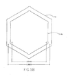
- FIG. 5B is a top view of the hollow shaped socket insert adapter of FIG. 1 , for use in conjunction with the socket driver, in accordance with another embodiment of the present invention.
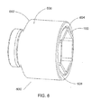
- FIG. 6 is a perspective view of the socket driver with the hollow shaped socket insert adapter of FIG. 1 conformed to the cavity of the socket driver, in accordance with an embodiment of the present invention.
- FIG. 7 is an illustrative view of the plurality of the hollow shaped socket insert adapters of FIG. 1 with variable inner diameter to use in conjunction with single socket driver, in accordance with an embodiment of the present invention.
- FIG. 9 is a perspective view of the hollow shaped socket insert adapter and socket driver with provision for spring ball detent, for use in conjunction with the socket driver, in accordance with another embodiment of the present invention.
- FIG. 10 is a perspective view of an additional embodiment of the invention showing the arrangement wherein the hollow shaped socket insert adapter is adapted to be employed along with the socket wrench to operate on nuts/bolts, in accordance with another embodiment of the present invention.
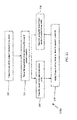
- FIG. 11 is a block diagram depicting the practice and use of the hollow shaped socket insert adapter, in accordance with an embodiment of the present invention.
- Embodiments of the present invention provide a socket insert for tightening, loosening, and removing various nuts/bolts of smaller dimensions used in conjunction with a single socket driver.
- the following detailed description is merely exemplary in nature and is not intended to limit the described embodiments or the application and uses of the described embodiments.
- the word "exemplary” or “illustrative” means “serving as an example, instance, or illustration.” Any implementation described herein as “exemplary” or “illustrative” is not necessarily to be construed as preferred or advantageous over other implementations.
- All of the implementations described below are exemplary implementations provided to enable persons skilled in the art to practice the disclosure and are not intended to limit the scope of the claims. Furthermore, there is no intention to be bound by any expressed or implied theory presented in the preceding technical field, background, brief summary or the following detailed description.
- Embodiments of the present invention provide a hollow shaped socket insert adapter rotatively driven by a single socket driver for tightening, loosing, and removing the various sizes of nuts/bolts.
- a plurality of hollow shaped socket insert adapters with variable inner diameter has been provided to operate on smaller dimensions of nuts/bolts.
- Hollow shaped socket insert adapters of different shapes to rotatively drive nuts/bolts of different shapes have also been provided.
- Each of the hollow shaped socket insert adapters is provided with rounded outside corners and rounded inside corners to maximize the torque on the flat wall of the insert adapter when rotatively driven by a socket driver.
- the hollow shaped socket insert adapter specific to the size of the subject nut/ bolt to be driven is chosen and placed inside the socket driver cavity. Force is applied to the socket driver body enabling the hollow shaped socket insert adapter to tighten, loosen, and remove the subject nut/bolt.
- FIG. 1 I present a perspective view of the hollow shaped socket insert adapter 100 for use in conjunction with the socket driver, in accordance with an embodiment of the present invention.
- Hollow shaped socket insert adapter 100 is a hollow insert that fits into the cavity of a socket driver.
- socket insert adapter 100 is composed of any metal to absorb heavy impact while being rotatively driven by a socket driver.
- metal include, but are not limited to steel, brass, iron, titanium, and copper.
- the hollow shaped socket insert adapter may be of any shape formed of edges. Examples of shapes include a square, hexagonal, octagonal, decagonal, and dodecagonal, any polygonal or any special shape.
- the socket insert adapter 100 is of varied sizes to accommodate the nuts/bolts of smaller dimensions with reference to the size of the socket driver.
- the sizes of the hollow shaped socket insert adapters are designed with different sizes, the sizes varying with a difference of at-least 1/16 inches (or about 1 mm). Most effective dimensions for the hollow shaped socket insert adapters vary from one inch (or 25mm) to 10 inch (or 255 mm).
- the socket insert adapter 100 has SAE (Society of Automotive Engineers) sizes.
- metric sizes corresponding to the SAE sizes are available.
- hollow shaped socket insert adapters have interchangeable SAE to metric sizes or vice versa.
- socket insert adapter 100 has an outer wall 102 and an inner wall 104 indicating that socket insert adapter 100 has a thickness 106.
- the thickness of the hollow shaped socket insert adapter is governed by the size of nuts/bolts to be driven.
- the outer wall of socket insert adapter 100 is structured to mechanically co-operate with the socket driver enabling it to conform to the cavity of the socket driver allowing it to tighten, loosen, and remove various smaller dimensions of nuts/bolts.
- the inner wall is configured to engage nuts/ bolts of smaller dimensions and fits on the head portion of nuts/bolts.
- socket insert adapter 100 has an outer configuration 108 and an inner configuration 110.
- the outer configuration is designed to conform to the cavity of a socket driver.
- the inner configuration interacts with the head portion of nuts/bolts to be driven.
- the construction of the outer configuration may or may not be similar to the construction of the inner configuration.
- the outer configuration of the hollow shaped socket insert adapter may be selected from, but not limited to, a circle, square, pentagonal, hexagonal, decagonal, dodecagonal, and any polygonal and the inner configuration of the hollow shape socket insert adapter may be selected from, but not limited to, a circle, square, pentagonal, hexagonal, decagonal, dodecagonal, and any polygonal, indicating that the hollow shape socket insert adapter that are 6pt. (hexagonal) on the outside can be 4pt, 5pt, 6pt, 8pt., 12pt., SAE or metric dimension on the "inside" of the hollow shaped socket insert adapter.
- FIG. 2 is a top view of hollow shaped socket insert adapter 100 of FIG. 1 for use in conjunction with the socket driver, in accordance with an embodiment of the present invention.
- socket insert adapter 100 has an outer diameter 112 to fit inside the socket driver cavity and a variable inner diameter 114 to operate on large range of smaller sizes of nuts/bolts.
- the variable inner diameter 114 of the hollow shaped socket insert adapter conforms to the head portion of nuts/bolts of different sizes.
- the hollow shaped socket insert adapter has rounded corners. Details corresponding to the rounded corners have been provided in conjunction with FIG. 3 .
- FIG. 3 is a magnified view of the corner of hollow shaped socket insert adapter 100 of FIG. 1 for use in conjunction with the socket driver, in accordance with an embodiment of the present invention.
- the socket insert adapter 100 is designed to have rounded "outside” corners 116 and rounded “inside” corners 118 which enables concentrating more torque upon the flat walls of the hollow shape insert rather than at corners. This helps to reduce the possibility of "rounded" corners upon the nut or bolt head portion being tightened or loosen.
- the rounded "outside” corners 116 and rounded “inside” corners 118 of the hollow shape socket insert adapter securely holds socket insert adapter 100 inside the socket driver cavity and prevents it from spinning and slippage.
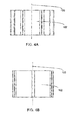
- FIG. 4A and FIG. 4B I present a cross sectional view of the hollow shape socket insert adapter 100 of FIG. 1 taken along the wall and along the corners respectively, for use in conjunction with the socket driver, in accordance with an embodiment of the present invention.
- the hollow shaped socket insert adapter has outer wall 102 concentric about longitudinal axis 120 configured to conform to the cavity of the socket driver.
- Socket insert adapter 100 is configured to slidably and non-rotatably engage a nut/bolt to be driven.
- FIG. 5A and FIG. B are top views of a hollow shaped socket insert adapter 100 of FIG. 1 , for use in conjunction with the socket driver, in accordance with an embodiment of the present invention.
- FIG. 5A and FIG. 5B present socket insert adapter 100 showing an outer diameter 112 to fit inside the socket driver cavity and a inner diameter 114a and 114b which is different for each case.
- the variable inner diameter is achieved by varying (increasing or decreasing) thickness 106 of the hollow shaped socket insert adapters.
- increasing the thickness of the hollow shaped socket insert adapter decreases the inner diameter of the hollow shape socket insert adapter.
- the varying inner diameter enables the hollow shaped socket insert adapter to tighten, remove, and loosen various nuts/bolts of smaller dimensions.
- FIG. 6 is a perspective view of socket driver 600 with hollow shaped socket insert adapter 100 of FIG. 1 conformed to the cavity 604 of the socket driver, in accordance with an embodiment of the present invention.
- FIG. 7 is an illustrative view of the plurality of hollow shaped socket insert adapters 700 of FIG. 1 with variable inner diameter to use in conjunction with single socket driver, in accordance with an embodiment of the present invention.
- the hollow shaped socket insert adapters 702a, 702b, 702c, 702d, 702e, 702f have a fixed outer diameter 112 and a different inner diameter 114.
- the sizes of the hollow shape socket insert adapters vary with a difference of at-least 1/16 inches (or about 1mm).
- the varying inner diameter 114 enables the hollow shape socket insert adapters to fit on different smaller dimensions of nuts/ bolts.
- one socket driver is enabled to be used to tighten, loosen, and remove nuts/bolts of different sizes and shapes.
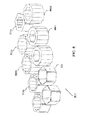
- FIG. 8 is an exemplary view of a plurality of hollow shaped socket insert adapters 800 of different shapes and different sizes for use in conjunction with the socket driver, in accordance with an embodiment of the present invention.
- the hollow shaped socket insert adapter has a fixed outer diameter 112 and a variable inner diameter 114.
- the variable inner diameter 114 of the hollow shape socket insert adapter conforms to the head portion of nuts/bolts of different sizes.
- Inserts 802a, 802b, 802c are examples of inserts having a fixed outer diameter and a variable inner diameter.
- the hollow shaped socket insert adapter has an outer configuration 108 and an inner configuration 110.
- the construction of the outer configuration may or may not be similar to the construction of the inner configuration.
- the outer configuration of the hollow shaped socket insert adapter may be selected from, but not limited to, a circle, square, pentagonal, hexagonal, decagonal, dodecagonal, and any polygonal
- the inner configuration of the hollow shape socket insert adapter may be selected from, but not limited to, a circle, square, pentagonal, hexagonal, decagonal, dodecagonal, and any polygonal.
- the combination of outer configurations 108 and inner configurations 110 vary in great variety.
- Inserts 804a, 804b, 804c are examples of inserts with different inner and outer configuration.
- the hollow shaped socket insert adapters are adapted to be used with spring ball detent. Details corresponding to inserts for spring ball detent have been provided in conjunction with FIG. 9 . Insert 806 is adapted to be used with spring ball detent.
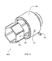
- FIG. 9 is a perspective view of the hollow shaped socket insert adapter with provision for spring ball detent 902, for use in conjunction with the socket diver, in accordance with another embodiment of the present invention.
- spring ball detent 902 can be added to socket driver 910 in manufacture, or afterwards as a modification.
- Spring ball detent 902 is a simple mechanical arrangement used to hold hollow shape socket insert 904 securely within socket driver 910 while operating upon nuts/bolts.
- the spring ball is a single, usually metal sphere, sliding within a bored cylinder, against the pressure of a spring, which pushes the ball against the hollow shaped socket insert adapter, which carries hole 906.
- Spring ball detent 902 passes through hole 910 (in the socket driver body) and hole 906 (in the hollow socket insert) to hold the hollow socket insert in place while rotatively driving the nuts/ bolts of different shapes and sizes.
- spring ball detent 902 is affixed permanently to the socket driver cavity wall.
- the hollow socket insert is held securely in place using a magnetic metal for production of hollow socket insert. In another embodiment of the present invention, the hollow socket insert is held in place using pins.
- FIG. 10 is a perspective view of an additional embodiment of the invention 1000 showing the arrangement wherein the hollow shape socket insert adapter is adapted to be employed along with the socket wrench to operate on nuts/bolts, in accordance with another embodiment of the present invention.
- Socket wrench 1002 is a type of tightening tool used to tighten, loosen, and remove nuts/bolts.
- socket wrench is an open end socket wrench 1004.
- socket wrench is a closed box end wrench 1006. The socket wrench is enabled to use socket insert adapter 100 for tightening, loosening, and removing nuts/bolts of different dimensions by receiving socket insert adapter 100 in the cavity at its end.
- I present a block diagram 1100 depicting the practice and use of the hollow shaped socket insert adapter, in accordance with an embodiment of the present invention.
- the dimension and shape of the nut/bolt to be driven is checked.
- an appropriate hollow shaped socket insert adapter specific to the size of subject nut or bolt head dimension is selected.
- the hollow shaped socket insert adapter is placed inside the socket driver cavity.
- hollow socket insert having a spring ball detent is placed within the socket driver/socket wrench cavity at step 208. Socket driver/socket wrench with hollow shaped socket insert adapter is now ready for application of torque to tighten, loosen, or remove the subject nut or bolt.
- torque force is applied on the socket driver/socket wrench. The torque force may be applied by manual, electric, hydraulic, or pneumatic means.
- the hollow shaped socket insert adapters described in the invention fulfill the objects set forth at the beginning of the description and provide means whereby a single socket driver/socket wrench may be employed to operate on a large range of nuts/bolts of different size and shapes at a substantial saving in weight, space, and cost.
Landscapes
- Engineering & Computer Science (AREA)
- Mechanical Engineering (AREA)
- Details Of Spanners, Wrenches, And Screw Drivers And Accessories (AREA)
Applications Claiming Priority (1)
| Application Number | Priority Date | Filing Date | Title |
|---|---|---|---|
| US12/434,609 US20100275738A1 (en) | 2009-05-01 | 2009-05-01 | Socket Insert Adapter |
Publications (2)
| Publication Number | Publication Date |
|---|---|
| EP2246155A2 true EP2246155A2 (fr) | 2010-11-03 |
| EP2246155A3 EP2246155A3 (fr) | 2012-12-12 |
Family
ID=42371942
Family Applications (1)
| Application Number | Title | Priority Date | Filing Date |
|---|---|---|---|
| EP10158578A Withdrawn EP2246155A3 (fr) | 2009-05-01 | 2010-03-31 | Adaptateur pour une clé à douille |
Country Status (3)
| Country | Link |
|---|---|
| US (1) | US20100275738A1 (fr) |
| EP (1) | EP2246155A3 (fr) |
| CA (1) | CA2699188C (fr) |
Families Citing this family (20)
| Publication number | Priority date | Publication date | Assignee | Title |
|---|---|---|---|---|
| USD639375S1 (en) * | 2010-02-11 | 2011-06-07 | OS Inc. | Octagonal firearm suppressor |
| USD642650S1 (en) * | 2010-05-28 | 2011-08-02 | OS Inc. | Decagonal firearm suppressor |
| USD643087S1 (en) * | 2010-05-28 | 2011-08-09 | OS Inc. | Nonagonal firearm suppressor |
| USD642649S1 (en) * | 2010-05-28 | 2011-08-02 | OS Inc. | Heptagonal firearm suppressor |
| USD642648S1 (en) * | 2010-05-28 | 2011-08-02 | OS Inc. | Hexagonal firearm suppressor |
| US9162350B2 (en) * | 2010-07-28 | 2015-10-20 | Eca Medical Instruments | Robust nose torque-limiting device |
| USD659495S1 (en) | 2011-10-20 | 2012-05-15 | Taylor James W Jr | Socket insert |
| US8863622B1 (en) * | 2012-01-16 | 2014-10-21 | Stanley Kingsberry | Magnetic wrench systems |
| US8667868B2 (en) | 2012-03-19 | 2014-03-11 | Hoa Mai | Water heater wrench adapter and method of use |
| DE102014212523B3 (de) * | 2014-06-27 | 2015-09-10 | Kipp Verpachtungen E.K. | Schonaufsatz für ein Ringschlüsselwerkzeug und zugehörige Ringschlüsselwerkzeug-Anordnung |
| USD796344S1 (en) * | 2015-06-10 | 2017-09-05 | Winehive, Inc. | Stackable storage unit or building unit |
| USD814567S1 (en) * | 2016-04-28 | 2018-04-03 | Travis Franklin | Ink cups |
| USD816163S1 (en) * | 2016-04-28 | 2018-04-24 | Travis Franklin | Ink cups |
| DE102018101593B4 (de) * | 2017-03-06 | 2020-03-19 | Armin Geiger-Rauch | Reduktionseinsatz und Satz aus Reduktionseinsätzen |
| KR102074249B1 (ko) * | 2018-04-04 | 2020-02-06 | 에이엠티 주식회사 | 가스통의 엔드 캡 이탈방지기능을 갖는 홀더 |
| TWI676527B (zh) * | 2019-03-07 | 2019-11-11 | 施能嘉 | 手工具用襯套結構 |
| USD1098794S1 (en) * | 2020-12-31 | 2025-10-21 | The Coca-Cola Company | Modular rack module |
| USD1102792S1 (en) * | 2020-12-31 | 2025-11-25 | The Coca-Cola Company | Modular rack |
| WO2024225191A1 (fr) * | 2023-04-28 | 2024-10-31 | 株式会社竹中製作所 | Douille interne |
| USD1124164S1 (en) * | 2025-02-13 | 2026-04-28 | Traxxas, L.P. | Model vehicle brake hex |
Citations (1)
| Publication number | Priority date | Publication date | Assignee | Title |
|---|---|---|---|---|
| EP1025959A2 (fr) * | 1999-02-08 | 2000-08-09 | Black & Decker Inc. | Clé |
Family Cites Families (14)
| Publication number | Priority date | Publication date | Assignee | Title |
|---|---|---|---|---|
| US608866A (en) * | 1898-08-09 | Wrench | ||
| US2337368A (en) * | 1941-09-19 | 1943-12-21 | Harlow V Greenwood | Wrench |
| US2376575A (en) * | 1942-10-24 | 1945-05-22 | James E Cronan | Ratchet wrench |
| US3027790A (en) * | 1959-04-06 | 1962-04-03 | Wagner William | Adapter for nuts, bolts, wrenches and the like |
| US3029673A (en) * | 1960-02-18 | 1962-04-17 | Godsey H Mitchell | Wrench size-reducing and nut sizeenlarging adapters |
| US3802303A (en) * | 1971-11-15 | 1974-04-09 | J Evans | Rachet-type speed wrench |
| US3875829A (en) * | 1973-02-20 | 1975-04-08 | James P Evans | Speed wrench adapter |
| US3916736A (en) * | 1973-11-12 | 1975-11-04 | James D Clemens | Identified wrench adaptor |
| US4836067A (en) * | 1984-01-16 | 1989-06-06 | Rogers Dale R | Protective socket insert |
| US4991468A (en) * | 1990-08-10 | 1991-02-12 | Lee Clark J | Barrel type sockets |
| DE10233866B4 (de) * | 2002-07-25 | 2018-01-25 | Wera Werk Hermann Werner Gmbh & Co. Kg | Schraubwerkzeug mit austauschbarem Schaft |
| US20050166725A1 (en) * | 2004-02-02 | 2005-08-04 | Shiu-E Chen | Fastening component assistive positioning device |
| US7334506B2 (en) * | 2004-12-06 | 2008-02-26 | David Hui | Anti-wearing socket and inner lining thereof |
| TW200808496A (en) * | 2006-08-04 | 2008-02-16 | Hou-Fei Hu | Skidproof socket with socket wall of uniform thickness |
-
2009
- 2009-05-01 US US12/434,609 patent/US20100275738A1/en not_active Abandoned
-
2010
- 2010-03-31 EP EP10158578A patent/EP2246155A3/fr not_active Withdrawn
- 2010-04-08 CA CA2699188A patent/CA2699188C/fr not_active Expired - Fee Related
Patent Citations (1)
| Publication number | Priority date | Publication date | Assignee | Title |
|---|---|---|---|---|
| EP1025959A2 (fr) * | 1999-02-08 | 2000-08-09 | Black & Decker Inc. | Clé |
Also Published As
| Publication number | Publication date |
|---|---|
| US20100275738A1 (en) | 2010-11-04 |
| CA2699188C (fr) | 2018-09-18 |
| CA2699188A1 (fr) | 2010-11-01 |
| EP2246155A3 (fr) | 2012-12-12 |
Similar Documents
| Publication | Publication Date | Title |
|---|---|---|
| CA2699188C (fr) | Insert adaptateur de douille | |
| US9511483B2 (en) | Socket insert adapter and method of use | |
| US10967488B2 (en) | Advanced holding apparatus | |
| US7434494B1 (en) | Socket driving tool | |
| EP3990221B1 (fr) | Appareil de support avancé | |
| US20170036324A1 (en) | Socket insert adapter and method of use | |
| JP6714262B2 (ja) | マルチグリップ・ソケットビット | |
| US6951156B2 (en) | Socket | |
| US20220040830A1 (en) | Advanced Holding Apparatus | |
| US20210220977A1 (en) | Advanced Holding Apparatus | |
| US10994391B2 (en) | Multi-functional socket tool | |
| US20130233133A1 (en) | Socket | |
| US20140196580A1 (en) | Multi-Bit Power Driver | |
| US7736100B2 (en) | Thread tap adapter | |
| US20100294087A1 (en) | Tool sleeve clamping structure | |
| CN205704047U (zh) | 组合工具 | |
| US7216568B1 (en) | Ratchet socket spanner | |
| CN212919147U (zh) | 一种多功能扳手 | |
| US12434360B2 (en) | Advanced holding apparatus | |
| US20250073865A1 (en) | Pass-through Socket Set With Impact Adaptor | |
| CN203062669U (zh) | 多用途组合扳手 | |
| US20230182274A1 (en) | Advanced Holding Apparatus | |
| AU2024219451B2 (en) | Advanced holding apparatus | |
| US20260008163A1 (en) | Device and method for changing wheel lug nut covers | |
| US20250073868A1 (en) | Advanced Holding Apparatus |
Legal Events
| Date | Code | Title | Description |
|---|---|---|---|
| PUAI | Public reference made under article 153(3) epc to a published international application that has entered the european phase |
Free format text: ORIGINAL CODE: 0009012 |
|
| AK | Designated contracting states |
Kind code of ref document: A2 Designated state(s): AT BE BG CH CY CZ DE DK EE ES FI FR GB GR HR HU IE IS IT LI LT LU LV MC MK MT NL NO PL PT RO SE SI SK SM TR |
|
| AX | Request for extension of the european patent |
Extension state: AL BA ME RS |
|
| PUAL | Search report despatched |
Free format text: ORIGINAL CODE: 0009013 |
|
| AK | Designated contracting states |
Kind code of ref document: A3 Designated state(s): AT BE BG CH CY CZ DE DK EE ES FI FR GB GR HR HU IE IS IT LI LT LU LV MC MK MT NL NO PL PT RO SE SI SK SM TR |
|
| AX | Request for extension of the european patent |
Extension state: AL BA ME RS |
|
| RIC1 | Information provided on ipc code assigned before grant |
Ipc: B25B 13/06 20060101ALI20121107BHEP Ipc: B25B 13/10 20060101AFI20121107BHEP Ipc: B25B 13/56 20060101ALI20121107BHEP |
|
| 17P | Request for examination filed |
Effective date: 20130524 |
|
| RBV | Designated contracting states (corrected) |
Designated state(s): AT BE BG CH CY CZ DE DK EE ES FI FR GB GR HR HU IE IS IT LI LT LU LV MC MK MT NL NO PL PT RO SE SI SK SM TR |
|
| 17Q | First examination report despatched |
Effective date: 20131219 |
|
| STAA | Information on the status of an ep patent application or granted ep patent |
Free format text: STATUS: THE APPLICATION HAS BEEN WITHDRAWN |
|
| 18W | Application withdrawn |
Effective date: 20151111 |