EP2246295A1 - Wasserstoffzuführvorrichtung - Google Patents
Wasserstoffzuführvorrichtung Download PDFInfo
- Publication number
- EP2246295A1 EP2246295A1 EP09712898A EP09712898A EP2246295A1 EP 2246295 A1 EP2246295 A1 EP 2246295A1 EP 09712898 A EP09712898 A EP 09712898A EP 09712898 A EP09712898 A EP 09712898A EP 2246295 A1 EP2246295 A1 EP 2246295A1
- Authority
- EP
- European Patent Office
- Prior art keywords
- hydrogen
- layer
- supply device
- metal layer
- permeation
- Prior art date
- Legal status (The legal status is an assumption and is not a legal conclusion. Google has not performed a legal analysis and makes no representation as to the accuracy of the status listed.)
- Granted
Links
Images


Classifications
-
- B—PERFORMING OPERATIONS; TRANSPORTING
- B01—PHYSICAL OR CHEMICAL PROCESSES OR APPARATUS IN GENERAL
- B01D—SEPARATION
- B01D53/00—Separation of gases or vapours; Recovering vapours of volatile solvents from gases; Chemical or biological purification of waste gases, e.g. engine exhaust gases, smoke, fumes, flue gases, aerosols
- B01D53/22—Separation of gases or vapours; Recovering vapours of volatile solvents from gases; Chemical or biological purification of waste gases, e.g. engine exhaust gases, smoke, fumes, flue gases, aerosols by diffusion
-
- B—PERFORMING OPERATIONS; TRANSPORTING
- B01—PHYSICAL OR CHEMICAL PROCESSES OR APPARATUS IN GENERAL
- B01D—SEPARATION
- B01D63/00—Apparatus in general for separation processes using semi-permeable membranes
-
- C—CHEMISTRY; METALLURGY
- C01—INORGANIC CHEMISTRY
- C01B—NON-METALLIC ELEMENTS; COMPOUNDS THEREOF; METALLOIDS OR COMPOUNDS THEREOF NOT COVERED BY SUBCLASS C01C
- C01B3/00—Hydrogen; Gaseous mixtures containing hydrogen; Separation of hydrogen from mixtures containing it; Purification of hydrogen; Reversible storage of hydrogen
- C01B3/50—Separation of hydrogen or hydrogen-containing gases from gaseous mixtures, e.g. purification
- C01B3/501—Separation of hydrogen or hydrogen-containing gases from gaseous mixtures, e.g. purification by diffusion
- C01B3/503—Separation of hydrogen or hydrogen-containing gases from gaseous mixtures, e.g. purification by diffusion characterised by membranes
-
- C—CHEMISTRY; METALLURGY
- C01—INORGANIC CHEMISTRY
- C01B—NON-METALLIC ELEMENTS; COMPOUNDS THEREOF; METALLOIDS OR COMPOUNDS THEREOF NOT COVERED BY SUBCLASS C01C
- C01B3/00—Hydrogen; Gaseous mixtures containing hydrogen; Separation of hydrogen from mixtures containing it; Purification of hydrogen; Reversible storage of hydrogen
- C01B3/50—Separation of hydrogen or hydrogen-containing gases from gaseous mixtures, e.g. purification
- C01B3/501—Separation of hydrogen or hydrogen-containing gases from gaseous mixtures, e.g. purification by diffusion
- C01B3/503—Separation of hydrogen or hydrogen-containing gases from gaseous mixtures, e.g. purification by diffusion characterised by membranes
- C01B3/505—Membranes containing palladium
-
- C—CHEMISTRY; METALLURGY
- C01—INORGANIC CHEMISTRY
- C01B—NON-METALLIC ELEMENTS; COMPOUNDS THEREOF; METALLOIDS OR COMPOUNDS THEREOF NOT COVERED BY SUBCLASS C01C
- C01B3/00—Hydrogen; Gaseous mixtures containing hydrogen; Separation of hydrogen from mixtures containing it; Purification of hydrogen; Reversible storage of hydrogen
- C01B3/50—Separation of hydrogen or hydrogen-containing gases from gaseous mixtures, e.g. purification
- C01B3/56—Separation of hydrogen or hydrogen-containing gases from gaseous mixtures, e.g. purification by contacting with solids; Regeneration of used solids
- C01B3/58—Separation of hydrogen or hydrogen-containing gases from gaseous mixtures, e.g. purification by contacting with solids; Regeneration of used solids including a catalytic reaction
-
- B—PERFORMING OPERATIONS; TRANSPORTING
- B01—PHYSICAL OR CHEMICAL PROCESSES OR APPARATUS IN GENERAL
- B01D—SEPARATION
- B01D2313/00—Details relating to membrane modules or apparatus
- B01D2313/08—Flow guidance means within the module or the apparatus
- B01D2313/086—Meandering flow path over the membrane
-
- C—CHEMISTRY; METALLURGY
- C01—INORGANIC CHEMISTRY
- C01B—NON-METALLIC ELEMENTS; COMPOUNDS THEREOF; METALLOIDS OR COMPOUNDS THEREOF NOT COVERED BY SUBCLASS C01C
- C01B2203/00—Integrated processes for the production of hydrogen or synthesis gas
- C01B2203/04—Integrated processes for the production of hydrogen or synthesis gas containing a purification step for the hydrogen or the synthesis gas
- C01B2203/0405—Purification by membrane separation
-
- C—CHEMISTRY; METALLURGY
- C01—INORGANIC CHEMISTRY
- C01B—NON-METALLIC ELEMENTS; COMPOUNDS THEREOF; METALLOIDS OR COMPOUNDS THEREOF NOT COVERED BY SUBCLASS C01C
- C01B2203/00—Integrated processes for the production of hydrogen or synthesis gas
- C01B2203/04—Integrated processes for the production of hydrogen or synthesis gas containing a purification step for the hydrogen or the synthesis gas
- C01B2203/0435—Catalytic purification
-
- C—CHEMISTRY; METALLURGY
- C01—INORGANIC CHEMISTRY
- C01B—NON-METALLIC ELEMENTS; COMPOUNDS THEREOF; METALLOIDS OR COMPOUNDS THEREOF NOT COVERED BY SUBCLASS C01C
- C01B2203/00—Integrated processes for the production of hydrogen or synthesis gas
- C01B2203/04—Integrated processes for the production of hydrogen or synthesis gas containing a purification step for the hydrogen or the synthesis gas
- C01B2203/0465—Composition of the impurity
-
- C—CHEMISTRY; METALLURGY
- C01—INORGANIC CHEMISTRY
- C01B—NON-METALLIC ELEMENTS; COMPOUNDS THEREOF; METALLOIDS OR COMPOUNDS THEREOF NOT COVERED BY SUBCLASS C01C
- C01B2203/00—Integrated processes for the production of hydrogen or synthesis gas
- C01B2203/04—Integrated processes for the production of hydrogen or synthesis gas containing a purification step for the hydrogen or the synthesis gas
- C01B2203/0465—Composition of the impurity
- C01B2203/0475—Composition of the impurity the impurity being carbon dioxide
-
- C—CHEMISTRY; METALLURGY
- C01—INORGANIC CHEMISTRY
- C01B—NON-METALLIC ELEMENTS; COMPOUNDS THEREOF; METALLOIDS OR COMPOUNDS THEREOF NOT COVERED BY SUBCLASS C01C
- C01B2203/00—Integrated processes for the production of hydrogen or synthesis gas
- C01B2203/06—Integration with other chemical processes
-
- H—ELECTRICITY
- H01—ELECTRIC ELEMENTS
- H01M—PROCESSES OR MEANS, e.g. BATTERIES, FOR THE DIRECT CONVERSION OF CHEMICAL ENERGY INTO ELECTRICAL ENERGY
- H01M8/00—Fuel cells; Manufacture thereof
- H01M8/06—Combination of fuel cells with means for production of reactants or for treatment of residues
- H01M8/0662—Treatment of gaseous reactants or gaseous residues, e.g. cleaning
- H01M8/0687—Reactant purification by the use of membranes or filters
-
- Y—GENERAL TAGGING OF NEW TECHNOLOGICAL DEVELOPMENTS; GENERAL TAGGING OF CROSS-SECTIONAL TECHNOLOGIES SPANNING OVER SEVERAL SECTIONS OF THE IPC; TECHNICAL SUBJECTS COVERED BY FORMER USPC CROSS-REFERENCE ART COLLECTIONS [XRACs] AND DIGESTS
- Y02—TECHNOLOGIES OR APPLICATIONS FOR MITIGATION OR ADAPTATION AGAINST CLIMATE CHANGE
- Y02E—REDUCTION OF GREENHOUSE GAS [GHG] EMISSIONS, RELATED TO ENERGY GENERATION, TRANSMISSION OR DISTRIBUTION
- Y02E60/00—Enabling technologies; Technologies with a potential or indirect contribution to GHG emissions mitigation
- Y02E60/30—Hydrogen technology
- Y02E60/50—Fuel cells
Definitions
- the present invention relates to a hydrogen supply device which supplies hydrogen by selectively permitting permeation of hydrogen contained in a hydrogen containing gas.
- Patent Document 1 discloses a hydrogen supply device which includes a dehydrogenation catalytic layer and a hydrogen dissociation membrane. According to the hydrogen supply device disclosed in Patent Document 1, hydrogen is supplied in such a manner that a mixed gas containing hydrogen is formed from a liquid hydrogen containing compound by the use of the dehydrogenation catalytic layer, and hydrogen contained in the mixed gas permeates the hydrogen dissociation membrane.
- the pressure of the mixed gas side needs to be relatively high, and the pressure of the hydrogen supply side needs to be relatively low. That is, in the conventional hydrogen supply device, a gradation of pressure is formed between the mixed gas side and the hydrogen supply side, and the permeation of the hydrogen is performed by the gradation of the pressure. For this reason, in order to allow the pressure of the mixed gas side to be relatively high and to allow the hydrogen supply side to be relatively low, it is necessary to install a large device such as a pump. For this reason, the energy consumption amount of an operating part increases. Further, as the device increases in size, and noise generated from the devise also increases during the operation thereof. In addition, when the permeation of the hydrogen is performed by the gradation of the pressure, it is difficult to dissociate the hydrogen in the case where the concentration of hydrogen contained in the hydrogen containing gas is low.
- a method which selectively absorbs hydrogen from a mixed gas by using absorbent.
- a pump is required, and a large volume of absorbents are required. For this reason, the device increases in size, and noise increases during the operation thereof as in the case of forming the gradation of the pressure.
- the absorbent needs to be exchanged periodically.
- the present invention is contrived in consideration of the above-described problems, and an object of the present invention is to provide a hydrogen supply device capable of dissociating hydrogen from a hydrogen containing gas even when the concentration of hydrogen is low and to suppress noise during the operation of the device.
- the present invention provides a hydrogen supply device which supplies hydrogen by selectively permitting permeation of hydrogen contained in a hydrogen containing gas, including: a first metal layer which dissociates hydrogen molecules into hydrogen ions by a catalytic reaction and has hydrogen permeability; a second metal layer which creates hydrogen molecules by bonding hydrogen ions to each other using electrons and has hydrogen permeability; a hydrogen permeation layer which is interposed between the first and second metal layers and permits permeation of the hydrogen ions from the first metal layer to the second metal layer by the application of a voltage; and a voltage application means for applying the voltage to the hydrogen permeation layer by setting the first metal layer as an anode and setting the second metal layer as a cathode.
- the voltage application portion applies a voltage to the hydrogen permeation layer so that the first metal layer is an anode and the second metal layer is a cathode
- hydrogen contained in a hydrogen containing gas is dissociated into hydrogen ions, and selectively permeates the hydrogen permeation layer. That is, according to the present invention, hydrogen molecules are selectively changed into hydrogen ions by the first metal layer, and a gradation of a voltage is formed between a hydrogen containing gas side and a hydrogen supply side, thereby selectively permitting the permeation of the hydrogen ions by the gradation of the voltage.
- the present invention may further include an electron supply amount control portion for controlling an amount of the electrons supplied to the second metal layer.
- the present invention may further include a gas diffusion portion for diffusing a hydrogen containing gas while being disposed on the opposite surface of the surface contacting with the hydrogen permeation layer of the first metal layer.
- the present invention may further include a gas diffusion portion for diffusion of hydrogen gas while being disposed on the opposite surface of the surface contacting with the hydrogen permeation layer of the second metal layer.
- the gas diffusion portion may have any one of a structure having a groove portion, a structure formed by sintered metal, and a structure formed by a grating-shaped metal plate or a lamination thereof.
- the present invention may further include a heating portion for heating a space where the hydrogen permeation layer is exposed.
- the present invention may further include a plurality of units including the first metal layer, the second metal layer, and the hydrogen permeation layer.
- the plurality of unitary units may be arranged in the lamination direction of the first metal layer, the second metal layer, and the hydrogen permeation layer.
- a gradation of a voltage is formed between the hydrogen containing gas side and the hydrogen supply side, and the permeation of hydrogen is performed by the gradation of the voltage. For this reason, a gradation of a pressure is not required between the hydrogen containing gas side and the hydrogen supply side, and a large device such as a pump does not need to be installed. Therefore, according to the hydrogen supply device of the present invention, it is possible to dissociate hydrogen from a hydrogen containing gas even when the concentration of hydrogen is low, and to suppress noise during the operation of the device.
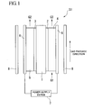
- FIG 1 is a schematic diagram showing a schematic configuration of a hydrogen supply device S1 of the embodiment.
- the hydrogen supply device S1 of the embodiment includes a cation exchange membrane 1 (a hydrogen permeation layer), a hydrogen dissociation layer 2 (a first metal layer and an anode), a hydrogen bonding layer 3 (a second metal layer and a cathode), a first conductive gas diffusion structure 4 (a gas diffusion portion), a second conductive gas diffusion structure 5 (a gas diffusion portion), an interconnection layer 6, a power supply device 7 (a voltage application portion and an electron supply amount control portion), and a heater 8 (a heating portion).
- a cation exchange membrane 1 a hydrogen permeation layer
- a hydrogen dissociation layer 2 a first metal layer and an anode
- a hydrogen bonding layer 3 a second metal layer and a cathode
- a first conductive gas diffusion structure 4 a gas diffusion portion
- a second conductive gas diffusion structure 5 a gas diffusion portion
- an interconnection layer 6
- the cation exchange membrane 1 (more specifically, a solid polymer type cation exchange membrane) is formed in a sheet shape.
- the hydrogen dissociation layer 2 is bonded to the anode-side surface of the cation exchange membrane 1
- the hydrogen bonding layer 3 is bonded to the other cathode-side surface of the cation exchange membrane 1, thereby sandwiching the cation exchange membrane by the hydrogen dissociation layer 2 and the hydrogen bonding layer 3.
- the hydrogen dissociation layer 2 side is relatively set to a high potential (anode), and the hydrogen bonding layer 3 side is relatively set to a low potential (cathode), thereby permeating hydrogen ions from the hydrogen dissociation layer 2 (anode side) to the hydrogen bonding layer 3 (cathode side). That is, the cation exchange membrane 1 permits permeation of hydrogen ions by the gradation of the voltage (potential).
- the cation exchange membrane 1 may be formed by any material if the material permits the permeation of hydrogen ions, for example, by the gradation of a voltage (potential), and may be formed by, for example, a material having a phosphoric group (PO 4 ) or a sulfonic group (SO 3 H) of a strong acid group.
- the hydrogen dissociation layer 2 is formed to have a metal structure function having a catalytic reaction of dissociating hydrogen molecules into hydrogen ions in the metal layer bonded to a surface of one side of the cation exchange membrane 1, and having hydrogen permeability.
- the hydrogen dissociation layer 2 is formed as a layer which dissociates hydrogen molecules into hydrogen ions by a catalytic reaction, and has hydrogen permeability.
- the hydrogen dissociation layer 2 may be formed by, for example, metal material of one or more of platinum (Pt), ruthenium (Ru), iron (Fe), cobalt (Co), titanium (Ti), palladium (Pd), nickel (Ni), potassium (K), magnesium (Mg), silicon (Si), and aluminum (Al), or may be formed by directly using oxide particles or the like of the metal materials.
- the hydrogen dissociation layer may be formed by using the mixture of carbon particles and the metal materials.
- the hydrogen dissociation layer may be formed by applying the metal materials onto the surfaces of the carbon particles. Further, as the metal materials, particularly, a metal material containing platinum (Pt) or ruthenium (Ru) may be very appropriately used.
- the hydrogen bonding layer 3 is formed by a metal structure function bonding hydrogen ions to each other using electrons in the metal layer bonded to the cathode-side surface of the cation exchange membrane 1, and having hydrogen permeability.
- the hydrogen bonding layer 3 is formed as a layer which bonds hydrogen ions to each other using electrons, and has hydrogen permeability.
- the hydrogen bonding layer 3 may be formed by, for example, metal material of one or more of platinum (Pt), ruthenium (Ru), iron (Fe), cobalt (Co), titanium (Ti), palladium (Pd), nickel (Ni), potassium (K), magnesium (Mg), silicon (Si), and aluminum (Al), or may be formed by directly using oxide particles or the like of the metal materials.
- the hydrogen bonding layer may be formed by using the mixture of carbon particles and the metal materials.
- the hydrogen bonding layer may be formed by applying the metal materials onto the surfaces of the carbon particles. Further, as the metal materials, particularly, a metal material containing platinum (Pt) or ruthenium (Ru) may be very appropriately used. That is, the hydrogen dissociation layer 2 and the hydrogen bonding layer 3 may be formed by the same metal material in some cases.
- the first conductive gas diffusion structure 4 is contacted and bonded to the entire surface opposite of the surface contacting with the cation exchange membrane 1 of the hydrogen dissociation layer 2.
- the contact with the entire surface means uniform contact with the entire surface in a dispersed state instead of contact with all positions of the entire surface.
- the first conductive gas diffusion structure 4 is formed by a material having higher conductivity than that of the hydrogen dissociation layer 2.
- the entire hydrogen dissociation layer 2 can be electrified via the first conductive gas diffusion structure 4.
- a gas is allowed to flow in the first conductive gas diffusion structure 4 in a direction (a direction (hereinafter, referred to as a gas passage direction) in which the first conductive gas diffusion structure 4 is disposed in FIG. 1 ) perpendicular to the direction of the hydrogen dissociation layer 2. Further, the first conductive gas diffusion structure 4 is formed so that the passing gas is dispersed and uniformly contacts with an entire surface of one side of the hydrogen dissociation layer 2. Specifically, as shown in FIG.
- the first conductive gas diffusion structure 4 is formed as a metal block 41, an opening end is formed in each of one opening end and the other opening end of the block 41 in the gas passage direction, and a meandering channel 42 is formed in an entire surface of one side of the hydrogen dissociation layer 2, thereby permitting the permeation of the gas in the gas passage direction of the first conductive gas diffusion structure 4, and the dispersed contact of the gas with the entire surface of one side of the hydrogen dissociation layer 2.
- the channel 42 is not limited to the one configuration shown in FIG. 2A , but may be branched into multiple parts in the course thereof.
- the channel 42 may be disposed in a grid shape as shown in FIG 2B .
- the first conductive gas diffusion structure 4 is formed as a powdered layer 43 formed by compressing powders of a conductive material as shown in FIG 3 , the gas is diffused in the powdered layer 43. For this reason, it is possible to form the first conductive gas diffusion structure 4 so that the permeation of the gas is permitted in the gas passage direction, and the uniform contact of the gas with the entire surface of one side of the hydrogen dissociation layer 2 in a dispersed state is permitted. Furthermore, when the first conductive gas diffusion structure 4 is formed as a grating-shaped structure 44 formed by a conductive material as shown in FIG 4 , the gas is diffused in the grating-shaped structure 44.
- the first conductive gas diffusion structure 4 may be formed by, for example, graphite.
- the second conductive gas diffusion structure 5 is contacted and bonded to the entire surface opposite of the surface contacting with the cation exchange membrane 1 of the hydrogen bonding layer 3.
- the contact with the entire surface means uniform contact with the entire surface in a dispersed state instead of contacting with all positions of the entire surface.
- the second conductive gas diffusion structure 5 is formed by a material having higher conductivity than that of the hydrogen bonding layer 3.
- the entire hydrogen bonding layer 3 can be electrified via the second conductive gas diffusion structure 5.
- the second conductive gas diffusion structure 5 is formed to discharge the hydrogen gas diffused in the gas passage direction as a direction perpendicular to the direction of the hydrogen bonding layer 3. Further, since it is necessary to efficiently collect the hydrogen gas penetrating the cation exchange membrane 1 in the one side of entire surface of the hydrogen bonding layer 3, it is desirable that the second conductive gas diffusion structure 5 adopts the configuration of assisting the gas diffusion as in the first conductive gas diffusion structure 4.
- the interconnection layer 6 is a metal layer which electrically connects the first conductive gas diffusion structure 4 and the second conductive gas diffusion structure 5 to the power supply device 7, and is installed in each of the first conductive gas diffusion structure 4 and the second conductive gas diffusion structure 5.
- the interconnection layer 6 installed in the first conductive gas diffusion structure 4 is bonded to the surface opposite of the surface contacting with the hydrogen dissociation layer 2 of the first conductive gas diffusion structure 4.
- the interconnection layer 6 installed in the second conductive gas diffusion structure 5 is bonded to the surface opposite of the surface contacting with the hydrogen bonding layer 3 of the second conductive gas diffusion structure 5.
- the power supply device 7 is a device which supplies power to the hydrogen dissociation layer 2 and the hydrogen bonding layer 3 while being electrically connected to the hydrogen dissociation layer 2 via the interconnection layer 6 and the first conductive gas diffusion structure 4 and electrically connected to the hydrogen bonding layer 3 via the interconnection layer 6 and the second conductive gas diffusion structure 5.
- the power supply device 7 supplies power so that the hydrogen dissociation layer 2 becomes an anode and the hydrogen bonding layer 3 becomes a cathode.
- the voltage and the current during the electrification of the power supply device 7 may be arbitrarily controlled.
- the power supply device 7 is able to arbitrarily control a difference in potential between the hydrogen dissociation layer 2 and the hydrogen bonding layer 3, and to further arbitrarily control an amount (current amount) of electrons supplied to the hydrogen bonding layer 3.
- the power supply device 7 has a voltage application portion and an electron supply amount control portion.
- the voltage application portion applies a voltage to the cation exchange membrane 1 by setting the hydrogen dissociation layer 2 as an anode and setting the hydrogen bonding layer 3 as a cathode.
- the electron supply amount control portion controls an amount (current amount) of electrons supplied to the hydrogen bonding layer 3.
- the heater 8 is used to heat a space where the cation exchange membrane 1 is exposed, and in the embodiment, heats the entire space where the cation exchange membrane 1, the hydrogen dissociation layer 2, the hydrogen bonding layer 3, the first conductive gas diffusion structure 4, the second conductive gas diffusion structure 5, and the interconnection layer 6 are exposed.
- the heater 8 is supported by a support body (not shown).
- a voltage is applied by the power supply device 7 so that the hydrogen dissociation layer 2 becomes anode, and the hydrogen bonding layer 3 becomes a cathode.
- a voltage is applied in this way, an electrical potential of one side of the cation exchange membrane 1 becomes higher than that of the other side, and an electrical potential of the other side thereof becomes lower than the one side, thereby forming a gradation of a voltage.
- the potential difference and/or the current amount between the hydrogen dissociation layer 2 and the hydrogen bonding layer 3 are uniformly maintained by the power supply device 7.
- a mixed gas G1 hydrogen containing gas
- the mixed gas G1 flows into the first conductive gas diffusion structure 4, and contacts a surface of one side the hydrogen dissociation layer 2.
- the mixed gas G1 includes nitrogen and carbon dioxide in addition to hydrogen.
- the first conductive gas diffusion structure 4 is formed so that the passing gas is dispersed and uniformly contacted with the entire surface of one side of the hydrogen dissociation layer 2.
- the hydrogen ions diffused in the inside of the hydrogen dissociation layer 2 arrives at the cation exchange membrane 1.
- a voltage is applied to the cation exchange membrane 1 so that the hydrogen dissociation layer 2 has a relatively high potential, and the hydrogen bonding layer 3 has a relatively low potential.
- the hydrogen ions arriving at the cation exchange membrane 1 permeate the cation exchange membrane from the hydrogen dissociation layer 2 to the hydrogen bonding layer 3 by the gradation of the voltage.
- the hydrogen ions penetrating the cation exchange membrane 1 from the hydrogen dissociation layer 2 to the hydrogen bonding layer 3 arrive at the hydrogen bonding layer 3, and are diffused inside of the hydrogen bonding layer 3.
- a voltage is applied by the power supply device 7 so that the hydrogen bonding layer 3 becomes a cathode. That is, electrons are supplied from the power supply device 7 to the hydrogen bonding layer 3 via the interconnection layer 6 and the second conductive gas diffusion structure 5. For this reason, the hydrogen ions diffused inside of the hydrogen bonding layer 3 are bonded to each other by the electrons, and are discharged from one surface (the surface on the second conductive gas diffusion structure 5 side) of the hydrogen bonding layer 3 in the form of hydrogen molecules.
- hydrogen gas G2 is discharged from the second conductive gas diffusion structure 5, thereby obtaining the hydrogen gas G2 which is refined by the hydrogen supply device of the embodiment.
- the mixed gas G1 supplied to the first conductive gas diffusion structure 4 from one side in the gas passage direction is discharged from the other side in the gas passage direction in the form of exhaust gas G3, of which the concentration of hydrogen is reduced, after the hydrogen is absorbed by the hydrogen dissociation layer 2.
- the hydrogen contained in the mixed gas G1 supplied to the anode side is dissociated into the hydrogen ions by the hydrogen dissociation layer 2, the hydrogen ions permeate the cation exchange membrane 1 by the gradation of the voltage, the hydrogen ions are bonded to each other using electrons in the hydrogen bonding layer 3 to be changed into hydrogen, and then the hydrogen gas G2 is discharged from the cathode side.
- the gradation of the voltage is formed between the mixed gas side and the hydrogen supply side, and the permeation of the hydrogen is performed by the gradation of the voltage. For this reason, the gradation of the pressure is not necessary between the mixed gas side and the hydrogen supply side, and a large device such as a pump does not need to be installed. Further, the hydrogen supply device S1 of the embodiment does not include a mechanical operating part. Therefore, according to the hydrogen supply device S1 of the embodiment, it is possible to dissociate hydrogen from the mixed gas G1, and to suppress noise during the operation of the device.
- the hydrogen bonding layer 3 two electrons are required to bond two hydrogen ions. That is, when two electrons are supplied to the hydrogen bonding layer 3, one hydrogen molecule can be obtained. For this reason, when the amount (i.e., the current amount) of electrons supplied to the hydrogen bonding layer 3 is controlled, it is possible to control the amount of hydrogen discharged from the hydrogen bonding layer 3.
- the power supply device 7 since the power supply device 7 is able to control the amount of electrons supplied to the hydrogen bonding layer 3 as described above, it is possible to arbitrarily control the supply amount of the hydrogen gas G2.
- the hydrogen supply device S1 of the embodiment since the value of the current amount can be highly precisely controlled by known technology, according to the hydrogen supply device S1 of the embodiment, it is possible to highly precisely control the supply amount of the hydrogen gas G2. In principle, it is possible to control the supply amount of the hydrogen gas G2 by the unit of one hydrogen molecule. Furthermore, when the amount of electrons supplied to the hydrogen bonding layer 3 is set to zero (i.e., a zero potential difference), it is possible to control the supply amount of the hydrogen gas G2 to be zero while supplying the mixed gas G1.
- the production amount (hydrogen permeation amount) of hydrogen molecules is dependent on the amount of electrons supplied to the hydrogen bonding layer 3. Accordingly, even when the concentration of hydrogen of the mixed gas G1 is low, it is possible to efficiently dissociate hydrogen from the mixed gas G1 having a low concentration of hydrogen by increasing the current amount or the electrical potential.
- the hydrogen supply device S1 of the embodiment it is possible to precisely and promptly control the supply amount of the hydrogen gas G1 to be an arbitrary value including zero by controlling the current amount. For this reason, in the case where the hydrogen gas is supplied instead of the mixed gas G1, the hydrogen supply device S1 of the embodiment can be used as a precise hydrogen supply device or a hydrogen valve capable of precisely and promptly controlling the supply amount of the hydrogen gas.
- the concentration of the hydrogen gas obtained by the above-described current amount or potential difference is not changed. For this reason, in the case where a variation in the supply amount of the hydrogen is permitted by the unit of time, a variation in the current amount or the potential difference is permitted. For this reason, for example, an electrical power generating device such as a wind power generating device having a variation in the current amount or the potential difference may be used as a power supply device. That is, according to the power supply device S1 of the embodiment, it is possible to obtain hydrogen gas from low-quality electrical power. In addition, it is possible to obtain high-quality electrical power from a fuel cell or the like by using the hydrogen gas obtained by the hydrogen supply device S1 of the embodiment as fuel. For this reason, the hydrogen supply device S1 of the embodiment may be used as a conversion device which converts low-quality electrical power into high-quality electrical power.
- the permeability of hydrogen ions changes in proportion to its exposed temperature within a predetermined range. For this reason, in the hydrogen supply device S1 of the embodiment, the cation exchange membrane 1 is heated by the heater 8 so that the cation exchange membrane 1 has desired permeability with respect to hydrogen ions.
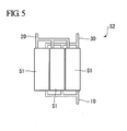
- FIG. 5 is a schematic diagram showing a schematic configuration of a hydrogen supply device S2 of the embodiment.
- the hydrogen supply device S2 of the embodiment includes a plurality of units S1, where one unit corresponds to one hydrogen supply device S1 of the first embodiment.
- the plurality of units S1 is arranged in the lamination direction (a direction perpendicular to the gas passage direction) of the cation exchange membrane 1, the hydrogen dissociation layer 2, and the hydrogen bonding layer 3.
- the hydrogen supply device S2 of the embodiment since the hydrogen supply device is formed by the plurality of units S1, it is possible to improve the hydrogen supply amount of the device without increasing the size of the unit of, for example, the cation exchange membrane 1, the hydrogen dissociation layer 2, and the hydrogen bonding layer 3.
- the plurality of units S1 since the plurality of units S1 is arranged in the lamination direction (the direction perpendicular to the gas passage direction) of the cation exchange membrane 1, the hydrogen dissociation layer 2, and the hydrogen bonding layer 3, it is possible to improve the hydrogen supply amount of the device without increasing the installation area of the device.
- the mixed gas G1 is supplied to the respective units S1 via a common pipe 10.
- the high-purity gas G2 discharged from the respective units S1 is collected via a common pipe 20 connected to the respective units S1, and then is discharged.
- the exhaust gas G3 is collected via a common pipe 30 connected to the units S1, and then is discharged.
- the power supply device 7 and the heater 8 are not shown in FIG. 5 , the power supply device 7 and the heater 8 may be installed for each of the unitary units, or one power supply device 7 and one heater 8 may be installed for all the unitary units S1.
- the configuration has been described in which the cation exchange membrane 1 is used as the hydrogen permeation layer of the present invention.
- the present invention is not limited thereto, but an ion exchange membrane obtained by alternately laminating a cation exchange membrane and an anion exchange membrane may be used.
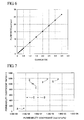
- FIG 6 is a graph showing a relationship between the current value and the flow rate of the hydrogen gas in the hydrogen supply device S1 of the first embodiment.
- the current value was changed within 3.5 A in the condition that the area of the cation exchange membrane 1 was set to 25 cm 2 , the potential difference was set to 0.1 V, and the heating temperature of the cation exchange membrane 1 was set to 60°C.
- a gas containing 54.44% of hydrogen, 22.94% of nitrogen, and 22.62% of carbon dioxide was used as the mixed gas G1, and the mixed gas G1 was supplied to the hydrogen supply device S1 at the flow rate of 48.73 ml/min.
- the supply amount of the mixed gas G1 was changed linearly with respect to a variation in the current value. Accordingly, according to the test, in the hydrogen supply device S1 of the first embodiment, it was found that the supply amount of the hydrogen gas could be controlled in proportion to the current value.
- FIG. 7 is a table comparing the hydrogen permeability coefficient of the existing hydrogen supply device with the hydrogen permeability coefficient of the hydrogen supply device S1 of the first embodiment, where the horizontal axis indicates the permeability coefficient, and the vertical axis indicates the permeability coefficient ratio.
- the permeability coefficient ratio is a value indicating a ratio between hydrogen and impure gas contained in the supplied mixed gas.
- the point A indicates the test value of the existing hydrogen supply device having an SiC-based hydrogen dissociation layer
- the point B indicates the test value of the existing hydrogen supply device having an Si-Ni-O membrane
- the point C indicates the test value of the existing hydrogen supply device having amorphous silica
- the points D and E indicate the test values of the existing hydrogen supply device having a palladium-based hydrogen permeation layer
- the point F indicates the test value of the hydrogen supply device S1 of the first embodiment in the case where the current value is 3.3 A in the test condition of FIG 6
- the point G indicates the test value of the hydrogen supply device S1 of the first embodiment in the case where the current value is 25 A in the test condition of FIG 6 .
- the test result shows that the permeability coefficient and the permeability coefficient ratio are better than those of the existing hydrogen supply device. Accordingly, according to the test, it is found that the hydrogen supply device S1 of the first embodiment is able to more efficiently supply the hydrogen than the existing hydrogen supply device.
- a hydrogen supply device capable of dissociating hydrogen from a hydrogen containing gas even when the concentration of hydrogen is low and suppressing noise during the operation of the device.
Landscapes
- Chemical & Material Sciences (AREA)
- Organic Chemistry (AREA)
- Engineering & Computer Science (AREA)
- Chemical Kinetics & Catalysis (AREA)
- Combustion & Propulsion (AREA)
- Inorganic Chemistry (AREA)
- Analytical Chemistry (AREA)
- General Chemical & Material Sciences (AREA)
- Oil, Petroleum & Natural Gas (AREA)
- Fuel Cell (AREA)
- Hydrogen, Water And Hydrids (AREA)
- Separation Using Semi-Permeable Membranes (AREA)
Applications Claiming Priority (2)
| Application Number | Priority Date | Filing Date | Title |
|---|---|---|---|
| JP2008037979A JP5071720B2 (ja) | 2008-02-19 | 2008-02-19 | 水素供給装置 |
| PCT/JP2009/052776 WO2009104638A1 (ja) | 2008-02-19 | 2009-02-18 | 水素供給装置 |
Publications (4)
| Publication Number | Publication Date |
|---|---|
| EP2246295A1 true EP2246295A1 (de) | 2010-11-03 |
| EP2246295A4 EP2246295A4 (de) | 2012-04-04 |
| EP2246295B1 EP2246295B1 (de) | 2018-08-15 |
| EP2246295B8 EP2246295B8 (de) | 2018-12-26 |
Family
ID=40985516
Family Applications (1)
| Application Number | Title | Priority Date | Filing Date |
|---|---|---|---|
| EP09712898.7A Not-in-force EP2246295B8 (de) | 2008-02-19 | 2009-02-18 | Wasserstoffzuführvorrichtung |
Country Status (4)
| Country | Link |
|---|---|
| US (1) | US8496736B2 (de) |
| EP (1) | EP2246295B8 (de) |
| JP (1) | JP5071720B2 (de) |
| WO (1) | WO2009104638A1 (de) |
Cited By (2)
| Publication number | Priority date | Publication date | Assignee | Title |
|---|---|---|---|---|
| WO2018069546A1 (en) * | 2016-10-14 | 2018-04-19 | Coorstek Membrane Sciences As | Process for producing compressed hydrogen in a membrane reactor and reactor therefor |
| US11677088B2 (en) | 2016-10-14 | 2023-06-13 | Coorstek Membrane Sciences As | Process for the manufacture of a solid oxide membrane electrode assembly |
Families Citing this family (2)
| Publication number | Priority date | Publication date | Assignee | Title |
|---|---|---|---|---|
| US20150202564A1 (en) * | 2013-01-22 | 2015-07-23 | Robert E. Kirby | Method For Permeation Extraction of Hydrogen From an Enclosed Volume |
| CA3175271A1 (en) * | 2020-03-09 | 2021-09-16 | Hyet Holding B.V. | Method and unit for extracting a component from a gas mixture and method for transporting a gas, in particular hydrogen or ammonium |
Family Cites Families (21)
| Publication number | Priority date | Publication date | Assignee | Title |
|---|---|---|---|---|
| US1495681A (en) * | 1922-04-11 | 1924-05-27 | Fauser Giacomo | Electrolyzer for producing hydrogen and oxygen |
| US1721407A (en) * | 1924-08-02 | 1929-07-16 | Pechkranz Rodolphe | Filter-press electrolyzer |
| US2070612A (en) * | 1932-03-19 | 1937-02-16 | Niederreither Hans | Method of producing, storing, and distributing electrical energy by operating gas batteries, particularly oxy-hydrogen gas batteries and electrolyzers |
| US4797185A (en) * | 1985-07-19 | 1989-01-10 | Allied-Signal Inc. | Hydrogen separation and electricity generation using novel electrolyte membrane |
| US5498278A (en) * | 1990-08-10 | 1996-03-12 | Bend Research, Inc. | Composite hydrogen separation element and module |
| US6036827A (en) * | 1997-06-27 | 2000-03-14 | Lynntech, Inc. | Electrolyzer |
| JP2001102076A (ja) | 1999-09-29 | 2001-04-13 | Daihatsu Motor Co Ltd | 燃料電池装置 |
| WO2001047053A1 (en) * | 1999-12-22 | 2001-06-28 | Proton Energy Systems, Inc. | Electrochemical cell system |
| US6620539B2 (en) * | 2000-03-13 | 2003-09-16 | Energy Conversion Devices, Inc. | Fuel cell cathodes and their fuel cells |
| US6833207B2 (en) * | 2001-11-09 | 2004-12-21 | Hydrogenics Corporation | Unitized regenerative fuel cell with bifunctional fuel cell humidifier and water electrolyzer |
| JP2004131306A (ja) | 2002-10-08 | 2004-04-30 | Honda Motor Co Ltd | 水素発生装置及び水素発生方法並びに水素回収装置及び水素回収方法 |
| EP1453131B1 (de) * | 2003-02-25 | 2009-11-11 | Aisin Seiki Kabushiki Kaisha | Brennstoffzelle mit interner Hilfselektrode und Verfahren zur Regelung |
| JP3815445B2 (ja) * | 2003-02-25 | 2006-08-30 | 栗田工業株式会社 | 水素ガスの精製装置及び精製方法 |
| JP4617648B2 (ja) * | 2003-02-27 | 2011-01-26 | トヨタ自動車株式会社 | 水素抽出装置 |
| JP4284095B2 (ja) * | 2003-04-04 | 2009-06-24 | 財団法人電力中央研究所 | 水素と二酸化炭素の製造装置 |
| JP3856769B2 (ja) * | 2003-06-20 | 2006-12-13 | 大同メタル工業株式会社 | 水の電気分解および発電機能を有する膜・電極接合体およびそれを用いた水の電気分解装置付き燃料電池 |
| WO2005077818A1 (en) * | 2004-02-06 | 2005-08-25 | David Tsay | Single stage membrane reactor for high purity hydrogen production |
| CN100541887C (zh) * | 2004-04-26 | 2009-09-16 | 东芝燃料电池动力系统公司 | 燃料电池及燃料电池的制造方法 |
| US20050252853A1 (en) * | 2004-05-13 | 2005-11-17 | Berland Brian S | Novel proton conducting materials and devices incorporating them |
| US7413687B2 (en) * | 2005-06-24 | 2008-08-19 | Ut - Battelle, Llc | Low temperature proton conducting oxide devices |
| US8920992B2 (en) * | 2009-06-08 | 2014-12-30 | Toyota Jidosha Kabushiki Kaisha | Hydrogen concentration measurement device and fuel cell system |
-
2008
- 2008-02-19 JP JP2008037979A patent/JP5071720B2/ja active Active
-
2009
- 2009-02-18 US US12/867,899 patent/US8496736B2/en active Active
- 2009-02-18 EP EP09712898.7A patent/EP2246295B8/de not_active Not-in-force
- 2009-02-18 WO PCT/JP2009/052776 patent/WO2009104638A1/ja not_active Ceased
Cited By (3)
| Publication number | Priority date | Publication date | Assignee | Title |
|---|---|---|---|---|
| WO2018069546A1 (en) * | 2016-10-14 | 2018-04-19 | Coorstek Membrane Sciences As | Process for producing compressed hydrogen in a membrane reactor and reactor therefor |
| US10981786B2 (en) | 2016-10-14 | 2021-04-20 | Coorstek Membrane Sciences As | Process for producing compressed hydrogen in a membrane reactor and reactor therefor |
| US11677088B2 (en) | 2016-10-14 | 2023-06-13 | Coorstek Membrane Sciences As | Process for the manufacture of a solid oxide membrane electrode assembly |
Also Published As
| Publication number | Publication date |
|---|---|
| EP2246295B8 (de) | 2018-12-26 |
| JP5071720B2 (ja) | 2012-11-14 |
| US20110076203A1 (en) | 2011-03-31 |
| US8496736B2 (en) | 2013-07-30 |
| JP2009196827A (ja) | 2009-09-03 |
| EP2246295A4 (de) | 2012-04-04 |
| WO2009104638A1 (ja) | 2009-08-27 |
| EP2246295B1 (de) | 2018-08-15 |
Similar Documents
| Publication | Publication Date | Title |
|---|---|---|
| JP7220368B2 (ja) | 水素供給システム | |
| JP7162258B2 (ja) | 水素供給システムおよび水素供給システムの運転方法 | |
| JP7149530B2 (ja) | 水素供給システムおよび水素供給システムの運転方法 | |
| US11577196B2 (en) | Electrochemical hydrogen pump | |
| US9518331B2 (en) | Hydrogen system and method of operation | |
| JP2022543214A (ja) | 電気化学セルおよび水素含有ガス気流を処理する方法 | |
| US8227133B2 (en) | Fuel cell system | |
| CN109563634B (zh) | 氢处理装置 | |
| JP2019119654A (ja) | 電気化学式水素ポンプ | |
| EP2246295B1 (de) | Wasserstoffzuführvorrichtung | |
| CN115867510A (zh) | 氢系统和氢系统的运行方法 | |
| JP2006260909A (ja) | 膜電極接合体およびこれを用いた固体高分子型燃料電池 | |
| CN116897449A (zh) | 用于制造用于燃料电池的催化剂层的方法 | |
| JP2008293964A (ja) | 発電装置及び発電方法 | |
| JP2019186160A (ja) | 燃料電池システム | |
| CN115558949A (zh) | 分离供电式氢气富集提纯加压电化学氢泵系统 | |
| Valdés López | Carbon Monoxide Poisoning Mechanisms and Mitigation Strategies for Polymer Electrolyte Membrane Fuel Cells | |
| JP6975922B1 (ja) | 水素システムおよび水素システムの運転方法 | |
| CN100558630C (zh) | 氢供给系统 | |
| JP2009120441A (ja) | 発電装置及び発電方法 | |
| WO2023112846A1 (ja) | 炭化水素系化合物の製造装置及び製造方法 | |
| JP2007052956A (ja) | 燃料電池 | |
| Rajala | Enhancement of polymer electrolyte fuel cell tolerance to CO | |
| JP2006108059A (ja) | 触媒電極 |
Legal Events
| Date | Code | Title | Description |
|---|---|---|---|
| PUAI | Public reference made under article 153(3) epc to a published international application that has entered the european phase |
Free format text: ORIGINAL CODE: 0009012 |
|
| 17P | Request for examination filed |
Effective date: 20100819 |
|
| AK | Designated contracting states |
Kind code of ref document: A1 Designated state(s): AT BE BG CH CY CZ DE DK EE ES FI FR GB GR HR HU IE IS IT LI LT LU LV MC MK MT NL NO PL PT RO SE SI SK TR |
|
| AX | Request for extension of the european patent |
Extension state: AL BA RS |
|
| DAX | Request for extension of the european patent (deleted) | ||
| A4 | Supplementary search report drawn up and despatched |
Effective date: 20120306 |
|
| RIC1 | Information provided on ipc code assigned before grant |
Ipc: C01B 3/58 20060101AFI20120229BHEP Ipc: B01D 53/22 20060101ALI20120229BHEP Ipc: B01D 71/02 20060101ALI20120229BHEP Ipc: H01M 8/06 20060101ALI20120229BHEP |
|
| 17Q | First examination report despatched |
Effective date: 20130412 |
|
| STAA | Information on the status of an ep patent application or granted ep patent |
Free format text: STATUS: EXAMINATION IS IN PROGRESS |
|
| REG | Reference to a national code |
Ref country code: DE Ref legal event code: R079 Ref document number: 602009053857 Country of ref document: DE Free format text: PREVIOUS MAIN CLASS: C01B0003580000 Ipc: C01B0003500000 |
|
| GRAP | Despatch of communication of intention to grant a patent |
Free format text: ORIGINAL CODE: EPIDOSNIGR1 |
|
| STAA | Information on the status of an ep patent application or granted ep patent |
Free format text: STATUS: GRANT OF PATENT IS INTENDED |
|
| RIC1 | Information provided on ipc code assigned before grant |
Ipc: H01M 8/0662 20160101ALI20180122BHEP Ipc: C01B 3/50 20060101AFI20180122BHEP Ipc: C01B 3/58 20060101ALI20180122BHEP Ipc: B01D 63/00 20060101ALI20180122BHEP |
|
| INTG | Intention to grant announced |
Effective date: 20180223 |
|
| GRAS | Grant fee paid |
Free format text: ORIGINAL CODE: EPIDOSNIGR3 |
|
| GRAA | (expected) grant |
Free format text: ORIGINAL CODE: 0009210 |
|
| STAA | Information on the status of an ep patent application or granted ep patent |
Free format text: STATUS: THE PATENT HAS BEEN GRANTED |
|
| AK | Designated contracting states |
Kind code of ref document: B1 Designated state(s): AT BE BG CH CY CZ DE DK EE ES FI FR GB GR HR HU IE IS IT LI LT LU LV MC MK MT NL NO PL PT RO SE SI SK TR |
|
| REG | Reference to a national code |
Ref country code: CH Ref legal event code: EP Ref country code: GB Ref legal event code: FG4D Ref country code: AT Ref legal event code: REF Ref document number: 1029515 Country of ref document: AT Kind code of ref document: T Effective date: 20180815 |
|
| RIN1 | Information on inventor provided before grant (corrected) |
Inventor name: TAKAHASHI, KATSUMI Inventor name: NISHINO, JUNYA Inventor name: OBARA, HIROYUKI |
|
| REG | Reference to a national code |
Ref country code: IE Ref legal event code: FG4D |
|
| REG | Reference to a national code |
Ref country code: DE Ref legal event code: R096 Ref document number: 602009053857 Country of ref document: DE |
|
| REG | Reference to a national code |
Ref country code: GB Ref legal event code: 732E Free format text: REGISTERED BETWEEN 20180830 AND 20180905 |
|
| REG | Reference to a national code |
Ref country code: CH Ref legal event code: PK Free format text: BERICHTIGUNGEN |
|
| REG | Reference to a national code |
Ref country code: CH Ref legal event code: PK Free format text: BERICHTIGUNG B8 |
|
| RIN2 | Information on inventor provided after grant (corrected) |
Inventor name: TAKAHASHI, KATSUMI Inventor name: NISHINO, JUNYA Inventor name: OBARA, HIROYUKI |
|
| REG | Reference to a national code |
Ref country code: NL Ref legal event code: MP Effective date: 20180815 |
|
| REG | Reference to a national code |
Ref country code: LT Ref legal event code: MG4D |
|
| REG | Reference to a national code |
Ref country code: DE Ref legal event code: R083 Ref document number: 602009053857 Country of ref document: DE |
|
| REG | Reference to a national code |
Ref country code: AT Ref legal event code: MK05 Ref document number: 1029515 Country of ref document: AT Kind code of ref document: T Effective date: 20180815 |
|
| PG25 | Lapsed in a contracting state [announced via postgrant information from national office to epo] |
Ref country code: LT Free format text: LAPSE BECAUSE OF FAILURE TO SUBMIT A TRANSLATION OF THE DESCRIPTION OR TO PAY THE FEE WITHIN THE PRESCRIBED TIME-LIMIT Effective date: 20180815 Ref country code: FI Free format text: LAPSE BECAUSE OF FAILURE TO SUBMIT A TRANSLATION OF THE DESCRIPTION OR TO PAY THE FEE WITHIN THE PRESCRIBED TIME-LIMIT Effective date: 20180815 Ref country code: IS Free format text: LAPSE BECAUSE OF FAILURE TO SUBMIT A TRANSLATION OF THE DESCRIPTION OR TO PAY THE FEE WITHIN THE PRESCRIBED TIME-LIMIT Effective date: 20181215 Ref country code: NL Free format text: LAPSE BECAUSE OF FAILURE TO SUBMIT A TRANSLATION OF THE DESCRIPTION OR TO PAY THE FEE WITHIN THE PRESCRIBED TIME-LIMIT Effective date: 20180815 Ref country code: BG Free format text: LAPSE BECAUSE OF FAILURE TO SUBMIT A TRANSLATION OF THE DESCRIPTION OR TO PAY THE FEE WITHIN THE PRESCRIBED TIME-LIMIT Effective date: 20181115 Ref country code: AT Free format text: LAPSE BECAUSE OF FAILURE TO SUBMIT A TRANSLATION OF THE DESCRIPTION OR TO PAY THE FEE WITHIN THE PRESCRIBED TIME-LIMIT Effective date: 20180815 Ref country code: NO Free format text: LAPSE BECAUSE OF FAILURE TO SUBMIT A TRANSLATION OF THE DESCRIPTION OR TO PAY THE FEE WITHIN THE PRESCRIBED TIME-LIMIT Effective date: 20181115 Ref country code: GR Free format text: LAPSE BECAUSE OF FAILURE TO SUBMIT A TRANSLATION OF THE DESCRIPTION OR TO PAY THE FEE WITHIN THE PRESCRIBED TIME-LIMIT Effective date: 20181116 Ref country code: SE Free format text: LAPSE BECAUSE OF FAILURE TO SUBMIT A TRANSLATION OF THE DESCRIPTION OR TO PAY THE FEE WITHIN THE PRESCRIBED TIME-LIMIT Effective date: 20180815 |
|
| REG | Reference to a national code |
Ref country code: CH Ref legal event code: PK Free format text: BERICHTIGUNGEN |
|
| RIC2 | Information provided on ipc code assigned after grant |
Ipc: H01M 8/0662 20160101ALI20180122BHEP Ipc: B01D 63/00 20060101ALI20180122BHEP Ipc: C01B 3/58 20060101ALI20180122BHEP Ipc: C01B 3/50 20060101AFI20180122BHEP |
|
| PG25 | Lapsed in a contracting state [announced via postgrant information from national office to epo] |
Ref country code: LV Free format text: LAPSE BECAUSE OF FAILURE TO SUBMIT A TRANSLATION OF THE DESCRIPTION OR TO PAY THE FEE WITHIN THE PRESCRIBED TIME-LIMIT Effective date: 20180815 Ref country code: HR Free format text: LAPSE BECAUSE OF FAILURE TO SUBMIT A TRANSLATION OF THE DESCRIPTION OR TO PAY THE FEE WITHIN THE PRESCRIBED TIME-LIMIT Effective date: 20180815 Ref country code: ES Free format text: LAPSE BECAUSE OF FAILURE TO SUBMIT A TRANSLATION OF THE DESCRIPTION OR TO PAY THE FEE WITHIN THE PRESCRIBED TIME-LIMIT Effective date: 20180815 |
|
| RAP2 | Party data changed (patent owner data changed or rights of a patent transferred) |
Owner name: OBARA, HIROYUKI |
|
| PG25 | Lapsed in a contracting state [announced via postgrant information from national office to epo] |
Ref country code: PL Free format text: LAPSE BECAUSE OF FAILURE TO SUBMIT A TRANSLATION OF THE DESCRIPTION OR TO PAY THE FEE WITHIN THE PRESCRIBED TIME-LIMIT Effective date: 20180815 Ref country code: EE Free format text: LAPSE BECAUSE OF FAILURE TO SUBMIT A TRANSLATION OF THE DESCRIPTION OR TO PAY THE FEE WITHIN THE PRESCRIBED TIME-LIMIT Effective date: 20180815 Ref country code: RO Free format text: LAPSE BECAUSE OF FAILURE TO SUBMIT A TRANSLATION OF THE DESCRIPTION OR TO PAY THE FEE WITHIN THE PRESCRIBED TIME-LIMIT Effective date: 20180815 Ref country code: IT Free format text: LAPSE BECAUSE OF FAILURE TO SUBMIT A TRANSLATION OF THE DESCRIPTION OR TO PAY THE FEE WITHIN THE PRESCRIBED TIME-LIMIT Effective date: 20180815 Ref country code: CZ Free format text: LAPSE BECAUSE OF FAILURE TO SUBMIT A TRANSLATION OF THE DESCRIPTION OR TO PAY THE FEE WITHIN THE PRESCRIBED TIME-LIMIT Effective date: 20180815 |
|
| REG | Reference to a national code |
Ref country code: DE Ref legal event code: R097 Ref document number: 602009053857 Country of ref document: DE |
|
| PG25 | Lapsed in a contracting state [announced via postgrant information from national office to epo] |
Ref country code: DK Free format text: LAPSE BECAUSE OF FAILURE TO SUBMIT A TRANSLATION OF THE DESCRIPTION OR TO PAY THE FEE WITHIN THE PRESCRIBED TIME-LIMIT Effective date: 20180815 Ref country code: SK Free format text: LAPSE BECAUSE OF FAILURE TO SUBMIT A TRANSLATION OF THE DESCRIPTION OR TO PAY THE FEE WITHIN THE PRESCRIBED TIME-LIMIT Effective date: 20180815 |
|
| PLBE | No opposition filed within time limit |
Free format text: ORIGINAL CODE: 0009261 |
|
| STAA | Information on the status of an ep patent application or granted ep patent |
Free format text: STATUS: NO OPPOSITION FILED WITHIN TIME LIMIT |
|
| 26N | No opposition filed |
Effective date: 20190516 |
|
| PG25 | Lapsed in a contracting state [announced via postgrant information from national office to epo] |
Ref country code: SI Free format text: LAPSE BECAUSE OF FAILURE TO SUBMIT A TRANSLATION OF THE DESCRIPTION OR TO PAY THE FEE WITHIN THE PRESCRIBED TIME-LIMIT Effective date: 20180815 |
|
| REG | Reference to a national code |
Ref country code: DE Ref legal event code: R119 Ref document number: 602009053857 Country of ref document: DE |
|
| REG | Reference to a national code |
Ref country code: CH Ref legal event code: PL |
|
| PG25 | Lapsed in a contracting state [announced via postgrant information from national office to epo] |
Ref country code: LU Free format text: LAPSE BECAUSE OF NON-PAYMENT OF DUE FEES Effective date: 20190218 Ref country code: MC Free format text: LAPSE BECAUSE OF FAILURE TO SUBMIT A TRANSLATION OF THE DESCRIPTION OR TO PAY THE FEE WITHIN THE PRESCRIBED TIME-LIMIT Effective date: 20180815 |
|
| REG | Reference to a national code |
Ref country code: BE Ref legal event code: MM Effective date: 20190228 |
|
| REG | Reference to a national code |
Ref country code: IE Ref legal event code: MM4A |
|
| PG25 | Lapsed in a contracting state [announced via postgrant information from national office to epo] |
Ref country code: CH Free format text: LAPSE BECAUSE OF NON-PAYMENT OF DUE FEES Effective date: 20190228 Ref country code: LI Free format text: LAPSE BECAUSE OF NON-PAYMENT OF DUE FEES Effective date: 20190228 |
|
| PG25 | Lapsed in a contracting state [announced via postgrant information from national office to epo] |
Ref country code: DE Free format text: LAPSE BECAUSE OF NON-PAYMENT OF DUE FEES Effective date: 20190903 Ref country code: IE Free format text: LAPSE BECAUSE OF NON-PAYMENT OF DUE FEES Effective date: 20190218 |
|
| PG25 | Lapsed in a contracting state [announced via postgrant information from national office to epo] |
Ref country code: FR Free format text: LAPSE BECAUSE OF NON-PAYMENT OF DUE FEES Effective date: 20190228 Ref country code: BE Free format text: LAPSE BECAUSE OF NON-PAYMENT OF DUE FEES Effective date: 20190228 |
|
| PG25 | Lapsed in a contracting state [announced via postgrant information from national office to epo] |
Ref country code: TR Free format text: LAPSE BECAUSE OF FAILURE TO SUBMIT A TRANSLATION OF THE DESCRIPTION OR TO PAY THE FEE WITHIN THE PRESCRIBED TIME-LIMIT Effective date: 20180815 |
|
| PG25 | Lapsed in a contracting state [announced via postgrant information from national office to epo] |
Ref country code: PT Free format text: LAPSE BECAUSE OF FAILURE TO SUBMIT A TRANSLATION OF THE DESCRIPTION OR TO PAY THE FEE WITHIN THE PRESCRIBED TIME-LIMIT Effective date: 20181215 Ref country code: MT Free format text: LAPSE BECAUSE OF NON-PAYMENT OF DUE FEES Effective date: 20190218 |
|
| PG25 | Lapsed in a contracting state [announced via postgrant information from national office to epo] |
Ref country code: CY Free format text: LAPSE BECAUSE OF FAILURE TO SUBMIT A TRANSLATION OF THE DESCRIPTION OR TO PAY THE FEE WITHIN THE PRESCRIBED TIME-LIMIT Effective date: 20180815 |
|
| PG25 | Lapsed in a contracting state [announced via postgrant information from national office to epo] |
Ref country code: HU Free format text: LAPSE BECAUSE OF FAILURE TO SUBMIT A TRANSLATION OF THE DESCRIPTION OR TO PAY THE FEE WITHIN THE PRESCRIBED TIME-LIMIT; INVALID AB INITIO Effective date: 20090218 |
|
| PG25 | Lapsed in a contracting state [announced via postgrant information from national office to epo] |
Ref country code: MK Free format text: LAPSE BECAUSE OF FAILURE TO SUBMIT A TRANSLATION OF THE DESCRIPTION OR TO PAY THE FEE WITHIN THE PRESCRIBED TIME-LIMIT Effective date: 20180815 |
|
| PGFP | Annual fee paid to national office [announced via postgrant information from national office to epo] |
Ref country code: GB Payment date: 20230217 Year of fee payment: 15 |
|
| GBPC | Gb: european patent ceased through non-payment of renewal fee |
Effective date: 20240218 |
|
| PG25 | Lapsed in a contracting state [announced via postgrant information from national office to epo] |
Ref country code: GB Free format text: LAPSE BECAUSE OF NON-PAYMENT OF DUE FEES Effective date: 20240218 |
|
| PG25 | Lapsed in a contracting state [announced via postgrant information from national office to epo] |
Ref country code: GB Free format text: LAPSE BECAUSE OF NON-PAYMENT OF DUE FEES Effective date: 20240218 |