EP2246483B1 - Schachtabdeckung - Google Patents
Schachtabdeckung Download PDFInfo
- Publication number
- EP2246483B1 EP2246483B1 EP20100250420 EP10250420A EP2246483B1 EP 2246483 B1 EP2246483 B1 EP 2246483B1 EP 20100250420 EP20100250420 EP 20100250420 EP 10250420 A EP10250420 A EP 10250420A EP 2246483 B1 EP2246483 B1 EP 2246483B1
- Authority
- EP
- European Patent Office
- Prior art keywords
- reinforcement
- reinforcement part
- cover
- frame
- ground surface
- Prior art date
- Legal status (The legal status is an assumption and is not a legal conclusion. Google has not performed a legal analysis and makes no representation as to the accuracy of the status listed.)
- Active
Links
Images



Classifications
-
- E—FIXED CONSTRUCTIONS
- E02—HYDRAULIC ENGINEERING; FOUNDATIONS; SOIL SHIFTING
- E02D—FOUNDATIONS; EXCAVATIONS; EMBANKMENTS; UNDERGROUND OR UNDERWATER STRUCTURES
- E02D29/00—Independent underground or underwater structures; Retaining walls
- E02D29/12—Manhole shafts; Other inspection or access chambers; Accessories therefor
- E02D29/14—Covers for manholes or the like; Frames for covers
- E02D29/1409—Covers for manholes or the like; Frames for covers adjustable in height or inclination
Definitions
- the present invention relates to ground surface access assemblies, and covers and frames therefor.
- Ground surface access assemblies such as gullies and manhole covers and frames are used in areas such as roadway services to provide access to underground services such as, for instance, drainage services and cable ducting.
- Such assemblies are commonly formed of cast iron and include a frame defining an access opening and a cover which is mounted to the frame in the opening.
- the assemblies have to be constructed to withstand a specified test regime which includes withstanding a test load, the amount of which is dependent on the particular location and trafficking for which the assembly is designed.
- testing regime applicable to ground surface access assemblies for use in locations such as roadways is currently set out in European Standard EN 124.
- an assembly In testing, an assembly must withstand a specified design load applied through a pad or plate to the cover or covers over the central part of the opening without an undue amount of deformation. Further constraints on the designers of such assemblies include ensuring that the product can be relatively easily manufactured; that product weight is minimised for cost and handling reasons; ensuring ease and safety of stacking of products for efficient transportation and storage; and ensuring ease of use for installers.
- the terms “upper” and “lower” are used relative to the orientation of a ground surface access assembly in an in use condition, in which the frame is supported on a support surface.
- a cover for a ground surface access assembly as defined in claim 1.
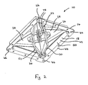
- Figs 1 to 3 show a ground surface access assembly 10, the assembly 10 including a frame 14 defining an access opening 50 and a pair of substantially identical covers 22 mountable to the frame 14 within the opening 50.
- the frame 14 and the covers 22 could be formed by casting, and could be formed of cast iron, and could be formed of ductile iron.
- Each of the covers 22 is substantially triangular in plan, having a pair of corners 54 which subtend an angle of substantially 45° and a 90° corner 56, each cover 22 including a relatively long hypotenuse side 58 which extends between the 45° corners 54 and a pair of relatively short sides 60, each of which extend between one of the 45° corners 54 and the 90° corner 56.
- Each cover 22 includes a mounting 34 projecting downwardly from the lower surface 20 at each of the corners 54, 56.
- Each cover 22 includes a substantially planar part 24 and a reinforcement arrangement 52, the reinforcement arrangement 52 including a first reinforcement part 16 which projects upwardly from an upper surface 26 of the planar part 24 and a second reinforcement part 30 which projects downwardly from a lower surface 28 of the planar part 24.
- the first reinforcement part 16 includes a main beam part 62 which extends substantially along a curved line extending between the two 45° corners 54, a pair of secondary reinforcement parts 64 which extend from the main beam part 62 towards the 90° corner 56, and a keyhole reinforcement part 66.
- the first reinforcement part 16 forms a raised, upwardly projecting surface pattern 70 on the upper surface 26.
- the surface pattern 70 could also include other projecting elements, which could be in the form of text and/or other shapes, and which could be of a different height to the first reinforcement part 16. The other projecting elements would not form part of the first reinforcement part 16.
- the first reinforcement part 16 projects upwardly from the upper surface 26 by a first reinforcement part projection height 68.
- the first reinforcement part projection height could be at least 2 mm, and could be less than 6 mm, and optimally could be approximately 4 mm.
- the second reinforcement part 30 includes a main beam part 72 which extends substantially along a curved line extending between the mountings 34 of the two 45° corners 54, a pair of secondary reinforcement parts 74, which extend from the main beam part 72 towards the mounting 34 of the 90° corner 56, and a keyhole reinforcement part 76.
- the reinforcement arrangement 52 also includes other reinforcement features 78 projecting downwardly from the lower surface 28, which could be in the form of auxiliary beams, webs, etc, which do not form part of the second reinforcement part 30.
- planar part 24, the first reinforcement part 16 and the second reinforcement part 30 are formed integrally.
- the shape and location of the first reinforcement part 16 when viewed in plan as shown in Figs 4 and 5 corresponds with the shape and location of the second reinforcement part 30, so that the second reinforcement part 30 is located substantially oppositely and below the first reinforcement part 16.
- the second reinforcement of main beam part 72 is substantially directly below the first reinforcement main beam part 62 as shown in figure 6
- the second reinforcement secondary parts 74 are substantially directly below the first reinforcement secondary parts 64.
- this provides the advantage that when subjected to test loading, in which a test load is applied through a pad or plate to the covers 22 above the central part of the opening 50, the first and second reinforcement parts 16, 30 act together as a simple beam.
- the first reinforcement part 16 extends the depth of the second reinforcement part 30 to increase the effective load-bearing capacity of the cover 22.
- a first reinforcement part 16 having a first reinforcement part projection height 68 of approximately 4 mm resulted in movement of the position of the neutral axis in a loading condition upwards by approximately 2 mm, when compared with the position of the neutral axis of a cover without a first reinforcement part 16, increasing the second moment of area for the portion in tension and resulting in an increase in load bearing capacity of 3.5 tonnes, an increase of 8.5%.
- the increase in load-bearing capacity permits the designer to reduce the weight of material in the cover 22, resulting in a cost saving.
- the width 80 of the first reinforcement part 16 is greater than the width 82 of the second reinforcement part 30 to allow for a degree of mismatch during the casting process of mould parts.
- the width 80 of the first reinforcement part 16 is approximately 2 mm greater than the width 82 of the second reinforcement part 30.
- the frame 14 includes a plurality of sidewalls 18, the sidewalls 18 including an upstanding part 42 and a flange part 44 which extends outwardly from a lower part in use of the upstanding part 42.
- the frame 14 includes a plurality of spacer projections 46 which extend downwardly from and in use lower surface 48 of the flange part 44.
- the frame 14 includes four spacer projections 46, each spacer projection 40 being located at a corner of the frame 14.
- Each spacer projection 46 extends inwardly from an outermost edge of the flange part 44 to a position which is located outboard of the upstanding part 42 in the vertical plane.
- Each spacer projection 46 projects by a spacer projection height 86.
- the spacer projection height 86 could be at least 5 mm, and could be no more than 15 mm. In one example, the spacer projection height 46 could be approximately 10 mm.
- Figure 3 shows the ground surface access assembly 10 in use.
- the frame 14 is located on a support surface 20.
- the spacer projections 46 space the sidewalls 18 from the support surface 20.
- a gap 84 is defined between the spacer projections 46, the lower surface 48 of the flange part 44 and the support surface 20.
- a bedding layer of a settable material such as mortar, resin concrete or an epoxy material is applied to the support surface 20, and the frame 14 located in the settable material so that the spacer projections 46 contact the support surface 20.
- the settable material fills the gap 84.
- the gap 84 is arranged so that, when filled, the settable material conforms to a specified minimum thickness.
- the spacer projections 46 permit a reduction in frame material weight, while permitting the overall height of the frame to be maintained, so that the depth of construction of the ground surface access assembly 10 of the invention is similar to that of a conventional ground surface access assembly.
- the overall height of a conventional frame is approximately 102 mm, while in the frame of the invention, the height of the sidewalls 18 could be approximately 92 mm and the spacer projection height 86 could be approximately 10 mm.
- a ground surface access assembly conforming to class D400 of European Standard EN 124 which included spacer projections 46 and first and second reinforcement parts 16, 30 had a weight of 65 kg, in comparison with a similar, conventional ground surface access assembly, which had a weight of 75 kg, a reduction in weight of over 13%.
- the assembly could include any suitable number of covers, and could include a single cover.
- the assembly, the frame and the cover or covers could be of any suitable size, shape and configuration. For example, when viewed in plan, the assembly could be substantially triangular, square, rectangular or circular in shape.
- the assembly, the frame and the cover or covers could be formed by any suitable method or combination of methods, and could be formed of any suitable material, such as aluminium or plastics.
- the reinforcement arrangement could include any suitable number of reinforcement parts, and the reinforcement parts could include any suitable number of elements, of any suitable size, shape or configuration.
- the assembly could include any suitable number of spacer projections, which could be of any suitable size, shape or configuration. To ensure non-rock mounting, the minimum number of spacer projections should be three.
- a ground surface access assembly including a cover and a frame which provides a number of advantages over conventional assemblies.
- the combination of the reinforcement arrangement of the invention with the spacer projections permits a significant reduction in weight to be achieved, reducing both manufacturing and transport costs and reducing handling risks on site, while providing an access assembly which can be manufactured using conventional materials and methods, and storage density is also increased, reducing storage costs.
Landscapes
- Engineering & Computer Science (AREA)
- Civil Engineering (AREA)
- Life Sciences & Earth Sciences (AREA)
- General Life Sciences & Earth Sciences (AREA)
- Mining & Mineral Resources (AREA)
- Paleontology (AREA)
- Environmental & Geological Engineering (AREA)
- General Engineering & Computer Science (AREA)
- Structural Engineering (AREA)
- Mechanical Engineering (AREA)
- Underground Structures, Protecting, Testing And Restoring Foundations (AREA)
- Sewage (AREA)
- Road Paving Structures (AREA)
Claims (5)
- Abdeckung (22) für eine Geländeoberflächen-Zugangsanordnung (10), wobei die Anordnung einen Rahmen (14) einschließt, der eine Zugangsöffnung (50) begrenzt, wobei die Abdeckung an dem Rahmen innerhalb der Öffnung anbringbar ist, die Abdeckung ein im Wesentlichen planes Teil (24) und eine Verstärkungsanordnung (52) einschließt, wobei die Verstärkungsanordnung ein zweites Verstärkungsteil (30) einschließt, das beim Gebrauch des planen Teils von einer Unterseite (28) nach unten vorsteht, dadurch gekennzeichnet, dass die Verstärkungsanordnung ein erstes Verstärkungsteil (16) einschließt, das von einer Oberseite (26) beim Gebrauch des planen Teils nach oben vorsteht, wobei die Form und Position des ersten Verstärkungsteils, in Draufsicht gesehen, der Form und Position des zweiten Verstärkungsteils entspricht, so dass das zweite Verstärkungsteil im Wesentlichen gegenüber und unter dem ersten Verstärkungsteil positioniert ist.
- Abdeckung nach Anspruch 1, wobei die Abdeckung ein erhöhtes, nach oben vorstehendes Oberflächenmuster (70) einschließt, das auf der Oberseite ausgebildet ist, und das erste Verstärkungsteil zumindest einen Teil des erhöhten Musters bildet.
- Abdeckung nach irgendeinem der vorhergehenden Ansprüche, wobei die maximale Breite des ersten Verstärkungsteils größer als die maximale Breite des zweiten Verstärkungsteils ist.
- Abdeckung nach irgendeinem der vorhergehenden Ansprüche, wobei das erste Verstärkungsteil über der Oberseite um eine Erstes-Verstärkungsteil-Projektionshöhe von mindestens 2 mm vorsteht.
- Abdeckung nach irgendeinem der vorhergehenden Ansprüche, wobei die Erstes-Verstärkungsteil-Projektionshöhe weniger als 6 mm beträgt.
Applications Claiming Priority (1)
| Application Number | Priority Date | Filing Date | Title |
|---|---|---|---|
| GB0903821A GB2468480B (en) | 2009-03-06 | 2009-03-06 | Ground surface access assemblies |
Publications (2)
| Publication Number | Publication Date |
|---|---|
| EP2246483A1 EP2246483A1 (de) | 2010-11-03 |
| EP2246483B1 true EP2246483B1 (de) | 2013-07-10 |
Family
ID=40600567
Family Applications (1)
| Application Number | Title | Priority Date | Filing Date |
|---|---|---|---|
| EP20100250420 Active EP2246483B1 (de) | 2009-03-06 | 2010-03-08 | Schachtabdeckung |
Country Status (2)
| Country | Link |
|---|---|
| EP (1) | EP2246483B1 (de) |
| GB (1) | GB2468480B (de) |
Families Citing this family (1)
| Publication number | Priority date | Publication date | Assignee | Title |
|---|---|---|---|---|
| GB201415380D0 (en) * | 2014-08-29 | 2014-10-15 | Wrekin Holdings Ltd | Ground surface access assemblies |
Family Cites Families (6)
| Publication number | Priority date | Publication date | Assignee | Title |
|---|---|---|---|---|
| GB247853A (en) * | 1925-09-04 | 1926-02-25 | Francis Shanley | Improvements in manholes |
| FR2749030B1 (fr) * | 1996-05-24 | 1998-07-24 | Norinco | Regard de chaussee a tampon articule sur un cadre |
| GB2374373B (en) * | 2001-04-12 | 2005-02-09 | Wrekin Welding & Fabrication E | Ground surface access assemblies |
| GB2429228B (en) * | 2005-08-02 | 2011-03-30 | Atlanta Impex Ltd | Access cover |
| GB0612154D0 (en) * | 2006-06-20 | 2006-08-02 | Wrekin Welding & Fabrication E | Surface access assemblies |
| GB2444769A (en) * | 2006-12-12 | 2008-06-18 | Wrekin Welding & Fabrication E | Ground surface access assembly |
-
2009
- 2009-03-06 GB GB0903821A patent/GB2468480B/en not_active Expired - Fee Related
-
2010
- 2010-03-08 EP EP20100250420 patent/EP2246483B1/de active Active
Also Published As
| Publication number | Publication date |
|---|---|
| GB0903821D0 (en) | 2009-04-22 |
| GB2468480B (en) | 2014-01-08 |
| EP2246483A1 (de) | 2010-11-03 |
| GB2468480A (en) | 2010-09-15 |
Similar Documents
| Publication | Publication Date | Title |
|---|---|---|
| AU2014401974B2 (en) | Percolation block element, percolation block, and transport unit | |
| KR101916744B1 (ko) | 강성이 향상된 교량 상부 구조물 및 이를 이용한 교량의 시공방법 | |
| CA2840139C (en) | Manhole cover | |
| US9586720B2 (en) | Pallet structure | |
| US12612756B2 (en) | Utility cover | |
| EP2246483B1 (de) | Schachtabdeckung | |
| EP1000201B1 (de) | Rahmen für eine schachtabdeckung | |
| KR102292294B1 (ko) | 공용중 교량 거더의 휨저항 성능 향상을 위한 강박스 거더 내부 보강방법 | |
| KR102061515B1 (ko) | 휨강성과 단면계수를 증가시킨 합성거더 및 그 합성거더를 이용한 가설구조물과 교량 | |
| CA2552052C (en) | A covering for an access aperture, and related assemblies | |
| EP2792794B1 (de) | Zugangsanordnungen für geschliffene Flächen | |
| WO2008007981A1 (en) | Access cover | |
| KR101205368B1 (ko) | 배수구 커버 | |
| KR101486140B1 (ko) | 보도 블록틀 | |
| JP2010133111A (ja) | 貯水槽用蓋部材および貯水槽 | |
| KR101426766B1 (ko) | 상치 콘크리트 구조물 및 이를 시공하는 방법 | |
| CN208792766U (zh) | 一种楼梯踏步模板 | |
| EP3775395B1 (de) | Verstärkte abdeckung für bodenoberflächenzugangsanordnung | |
| US20250109601A1 (en) | Reinforced pool structure | |
| GB2376495A (en) | Frame arrangement for ground surface access assembly | |
| KR20220025763A (ko) | 춤이 깊은 데크플레이트 및 이에 사용되는 보강편재 | |
| KR100803783B1 (ko) | 조립식 측벽블록 | |
| KR20100006911U (ko) | 차량의 하중형태를 고려한 맨홀 커버 | |
| JP2013053452A (ja) | 側溝蓋 | |
| HK1101642B (en) | A covering for an access aperture, and related assemblies |
Legal Events
| Date | Code | Title | Description |
|---|---|---|---|
| PUAI | Public reference made under article 153(3) epc to a published international application that has entered the european phase |
Free format text: ORIGINAL CODE: 0009012 |
|
| AK | Designated contracting states |
Kind code of ref document: A1 Designated state(s): AT BE BG CH CY CZ DE DK EE ES FI FR GB GR HR HU IE IS IT LI LT LU LV MC MK MT NL NO PL PT RO SE SI SK SM TR |
|
| AX | Request for extension of the european patent |
Extension state: AL BA ME RS |
|
| 17P | Request for examination filed |
Effective date: 20110503 |
|
| GRAP | Despatch of communication of intention to grant a patent |
Free format text: ORIGINAL CODE: EPIDOSNIGR1 |
|
| GRAS | Grant fee paid |
Free format text: ORIGINAL CODE: EPIDOSNIGR3 |
|
| GRAA | (expected) grant |
Free format text: ORIGINAL CODE: 0009210 |
|
| AK | Designated contracting states |
Kind code of ref document: B1 Designated state(s): AT BE BG CH CY CZ DE DK EE ES FI FR GB GR HR HU IE IS IT LI LT LU LV MC MK MT NL NO PL PT RO SE SI SK SM TR |
|
| REG | Reference to a national code |
Ref country code: GB Ref legal event code: FG4D |
|
| REG | Reference to a national code |
Ref country code: AT Ref legal event code: REF Ref document number: 621064 Country of ref document: AT Kind code of ref document: T Effective date: 20130715 Ref country code: CH Ref legal event code: EP |
|
| REG | Reference to a national code |
Ref country code: IE Ref legal event code: FG4D |
|
| REG | Reference to a national code |
Ref country code: DE Ref legal event code: R096 Ref document number: 602010008388 Country of ref document: DE Effective date: 20130905 |
|
| PG25 | Lapsed in a contracting state [announced via postgrant information from national office to epo] |
Ref country code: SI Free format text: LAPSE BECAUSE OF FAILURE TO SUBMIT A TRANSLATION OF THE DESCRIPTION OR TO PAY THE FEE WITHIN THE PRESCRIBED TIME-LIMIT Effective date: 20130710 |
|
| REG | Reference to a national code |
Ref country code: AT Ref legal event code: MK05 Ref document number: 621064 Country of ref document: AT Kind code of ref document: T Effective date: 20130710 |
|
| REG | Reference to a national code |
Ref country code: NL Ref legal event code: VDEP Effective date: 20130710 |
|
| REG | Reference to a national code |
Ref country code: LT Ref legal event code: MG4D |
|
| PG25 | Lapsed in a contracting state [announced via postgrant information from national office to epo] |
Ref country code: AT Free format text: LAPSE BECAUSE OF FAILURE TO SUBMIT A TRANSLATION OF THE DESCRIPTION OR TO PAY THE FEE WITHIN THE PRESCRIBED TIME-LIMIT Effective date: 20130710 Ref country code: SE Free format text: LAPSE BECAUSE OF FAILURE TO SUBMIT A TRANSLATION OF THE DESCRIPTION OR TO PAY THE FEE WITHIN THE PRESCRIBED TIME-LIMIT Effective date: 20130710 Ref country code: CY Free format text: LAPSE BECAUSE OF FAILURE TO SUBMIT A TRANSLATION OF THE DESCRIPTION OR TO PAY THE FEE WITHIN THE PRESCRIBED TIME-LIMIT Effective date: 20130710 Ref country code: LT Free format text: LAPSE BECAUSE OF FAILURE TO SUBMIT A TRANSLATION OF THE DESCRIPTION OR TO PAY THE FEE WITHIN THE PRESCRIBED TIME-LIMIT Effective date: 20130710 Ref country code: NO Free format text: LAPSE BECAUSE OF FAILURE TO SUBMIT A TRANSLATION OF THE DESCRIPTION OR TO PAY THE FEE WITHIN THE PRESCRIBED TIME-LIMIT Effective date: 20131010 Ref country code: IS Free format text: LAPSE BECAUSE OF FAILURE TO SUBMIT A TRANSLATION OF THE DESCRIPTION OR TO PAY THE FEE WITHIN THE PRESCRIBED TIME-LIMIT Effective date: 20131110 Ref country code: HR Free format text: LAPSE BECAUSE OF FAILURE TO SUBMIT A TRANSLATION OF THE DESCRIPTION OR TO PAY THE FEE WITHIN THE PRESCRIBED TIME-LIMIT Effective date: 20130710 Ref country code: BE Free format text: LAPSE BECAUSE OF FAILURE TO SUBMIT A TRANSLATION OF THE DESCRIPTION OR TO PAY THE FEE WITHIN THE PRESCRIBED TIME-LIMIT Effective date: 20130710 Ref country code: PT Free format text: LAPSE BECAUSE OF FAILURE TO SUBMIT A TRANSLATION OF THE DESCRIPTION OR TO PAY THE FEE WITHIN THE PRESCRIBED TIME-LIMIT Effective date: 20131111 |
|
| PG25 | Lapsed in a contracting state [announced via postgrant information from national office to epo] |
Ref country code: FI Free format text: LAPSE BECAUSE OF FAILURE TO SUBMIT A TRANSLATION OF THE DESCRIPTION OR TO PAY THE FEE WITHIN THE PRESCRIBED TIME-LIMIT Effective date: 20130710 Ref country code: GR Free format text: LAPSE BECAUSE OF FAILURE TO SUBMIT A TRANSLATION OF THE DESCRIPTION OR TO PAY THE FEE WITHIN THE PRESCRIBED TIME-LIMIT Effective date: 20131011 Ref country code: PL Free format text: LAPSE BECAUSE OF FAILURE TO SUBMIT A TRANSLATION OF THE DESCRIPTION OR TO PAY THE FEE WITHIN THE PRESCRIBED TIME-LIMIT Effective date: 20130710 Ref country code: LV Free format text: LAPSE BECAUSE OF FAILURE TO SUBMIT A TRANSLATION OF THE DESCRIPTION OR TO PAY THE FEE WITHIN THE PRESCRIBED TIME-LIMIT Effective date: 20130710 Ref country code: NL Free format text: LAPSE BECAUSE OF FAILURE TO SUBMIT A TRANSLATION OF THE DESCRIPTION OR TO PAY THE FEE WITHIN THE PRESCRIBED TIME-LIMIT Effective date: 20130710 Ref country code: ES Free format text: LAPSE BECAUSE OF FAILURE TO SUBMIT A TRANSLATION OF THE DESCRIPTION OR TO PAY THE FEE WITHIN THE PRESCRIBED TIME-LIMIT Effective date: 20131021 |
|
| PG25 | Lapsed in a contracting state [announced via postgrant information from national office to epo] |
Ref country code: SK Free format text: LAPSE BECAUSE OF FAILURE TO SUBMIT A TRANSLATION OF THE DESCRIPTION OR TO PAY THE FEE WITHIN THE PRESCRIBED TIME-LIMIT Effective date: 20130710 Ref country code: CZ Free format text: LAPSE BECAUSE OF FAILURE TO SUBMIT A TRANSLATION OF THE DESCRIPTION OR TO PAY THE FEE WITHIN THE PRESCRIBED TIME-LIMIT Effective date: 20130710 Ref country code: DK Free format text: LAPSE BECAUSE OF FAILURE TO SUBMIT A TRANSLATION OF THE DESCRIPTION OR TO PAY THE FEE WITHIN THE PRESCRIBED TIME-LIMIT Effective date: 20130710 Ref country code: EE Free format text: LAPSE BECAUSE OF FAILURE TO SUBMIT A TRANSLATION OF THE DESCRIPTION OR TO PAY THE FEE WITHIN THE PRESCRIBED TIME-LIMIT Effective date: 20130710 Ref country code: RO Free format text: LAPSE BECAUSE OF FAILURE TO SUBMIT A TRANSLATION OF THE DESCRIPTION OR TO PAY THE FEE WITHIN THE PRESCRIBED TIME-LIMIT Effective date: 20130710 |
|
| PLBE | No opposition filed within time limit |
Free format text: ORIGINAL CODE: 0009261 |
|
| STAA | Information on the status of an ep patent application or granted ep patent |
Free format text: STATUS: NO OPPOSITION FILED WITHIN TIME LIMIT |
|
| PG25 | Lapsed in a contracting state [announced via postgrant information from national office to epo] |
Ref country code: IT Free format text: LAPSE BECAUSE OF FAILURE TO SUBMIT A TRANSLATION OF THE DESCRIPTION OR TO PAY THE FEE WITHIN THE PRESCRIBED TIME-LIMIT Effective date: 20130710 |
|
| 26N | No opposition filed |
Effective date: 20140411 |
|
| REG | Reference to a national code |
Ref country code: DE Ref legal event code: R097 Ref document number: 602010008388 Country of ref document: DE Effective date: 20140411 |
|
| PG25 | Lapsed in a contracting state [announced via postgrant information from national office to epo] |
Ref country code: LU Free format text: LAPSE BECAUSE OF FAILURE TO SUBMIT A TRANSLATION OF THE DESCRIPTION OR TO PAY THE FEE WITHIN THE PRESCRIBED TIME-LIMIT Effective date: 20140308 |
|
| REG | Reference to a national code |
Ref country code: CH Ref legal event code: PL |
|
| REG | Reference to a national code |
Ref country code: IE Ref legal event code: MM4A |
|
| PG25 | Lapsed in a contracting state [announced via postgrant information from national office to epo] |
Ref country code: IE Free format text: LAPSE BECAUSE OF NON-PAYMENT OF DUE FEES Effective date: 20140308 Ref country code: CH Free format text: LAPSE BECAUSE OF NON-PAYMENT OF DUE FEES Effective date: 20140331 Ref country code: LI Free format text: LAPSE BECAUSE OF NON-PAYMENT OF DUE FEES Effective date: 20140331 |
|
| PG25 | Lapsed in a contracting state [announced via postgrant information from national office to epo] |
Ref country code: MT Free format text: LAPSE BECAUSE OF FAILURE TO SUBMIT A TRANSLATION OF THE DESCRIPTION OR TO PAY THE FEE WITHIN THE PRESCRIBED TIME-LIMIT Effective date: 20130710 |
|
| REG | Reference to a national code |
Ref country code: FR Ref legal event code: PLFP Year of fee payment: 7 |
|
| PG25 | Lapsed in a contracting state [announced via postgrant information from national office to epo] |
Ref country code: SM Free format text: LAPSE BECAUSE OF FAILURE TO SUBMIT A TRANSLATION OF THE DESCRIPTION OR TO PAY THE FEE WITHIN THE PRESCRIBED TIME-LIMIT Effective date: 20130710 |
|
| PG25 | Lapsed in a contracting state [announced via postgrant information from national office to epo] |
Ref country code: MC Free format text: LAPSE BECAUSE OF FAILURE TO SUBMIT A TRANSLATION OF THE DESCRIPTION OR TO PAY THE FEE WITHIN THE PRESCRIBED TIME-LIMIT Effective date: 20130710 |
|
| PG25 | Lapsed in a contracting state [announced via postgrant information from national office to epo] |
Ref country code: BG Free format text: LAPSE BECAUSE OF FAILURE TO SUBMIT A TRANSLATION OF THE DESCRIPTION OR TO PAY THE FEE WITHIN THE PRESCRIBED TIME-LIMIT Effective date: 20130710 |
|
| PG25 | Lapsed in a contracting state [announced via postgrant information from national office to epo] |
Ref country code: TR Free format text: LAPSE BECAUSE OF FAILURE TO SUBMIT A TRANSLATION OF THE DESCRIPTION OR TO PAY THE FEE WITHIN THE PRESCRIBED TIME-LIMIT Effective date: 20130710 Ref country code: HU Free format text: LAPSE BECAUSE OF FAILURE TO SUBMIT A TRANSLATION OF THE DESCRIPTION OR TO PAY THE FEE WITHIN THE PRESCRIBED TIME-LIMIT; INVALID AB INITIO Effective date: 20100308 |
|
| REG | Reference to a national code |
Ref country code: FR Ref legal event code: PLFP Year of fee payment: 8 |
|
| REG | Reference to a national code |
Ref country code: FR Ref legal event code: PLFP Year of fee payment: 9 |
|
| PG25 | Lapsed in a contracting state [announced via postgrant information from national office to epo] |
Ref country code: MK Free format text: LAPSE BECAUSE OF FAILURE TO SUBMIT A TRANSLATION OF THE DESCRIPTION OR TO PAY THE FEE WITHIN THE PRESCRIBED TIME-LIMIT Effective date: 20130710 |
|
| PGFP | Annual fee paid to national office [announced via postgrant information from national office to epo] |
Ref country code: DE Payment date: 20180403 Year of fee payment: 9 |
|
| REG | Reference to a national code |
Ref country code: DE Ref legal event code: R119 Ref document number: 602010008388 Country of ref document: DE |
|
| PG25 | Lapsed in a contracting state [announced via postgrant information from national office to epo] |
Ref country code: DE Free format text: LAPSE BECAUSE OF NON-PAYMENT OF DUE FEES Effective date: 20191001 |
|
| PGFP | Annual fee paid to national office [announced via postgrant information from national office to epo] |
Ref country code: GB Payment date: 20260325 Year of fee payment: 17 |
|
| PGFP | Annual fee paid to national office [announced via postgrant information from national office to epo] |
Ref country code: FR Payment date: 20260327 Year of fee payment: 17 |