EP2246495A1 - Trennwandsystem - Google Patents
Trennwandsystem Download PDFInfo
- Publication number
- EP2246495A1 EP2246495A1 EP09005670A EP09005670A EP2246495A1 EP 2246495 A1 EP2246495 A1 EP 2246495A1 EP 09005670 A EP09005670 A EP 09005670A EP 09005670 A EP09005670 A EP 09005670A EP 2246495 A1 EP2246495 A1 EP 2246495A1
- Authority
- EP
- European Patent Office
- Prior art keywords
- profile
- partitioning system
- coupling
- panel
- support
- Prior art date
- Legal status (The legal status is an assumption and is not a legal conclusion. Google has not performed a legal analysis and makes no representation as to the accuracy of the status listed.)
- Withdrawn
Links
- 238000000638 solvent extraction Methods 0.000 title claims abstract description 46
- 230000008878 coupling Effects 0.000 claims abstract description 55
- 238000010168 coupling process Methods 0.000 claims abstract description 55
- 238000005859 coupling reaction Methods 0.000 claims abstract description 55
- 239000011521 glass Substances 0.000 claims abstract description 19
- 238000001125 extrusion Methods 0.000 claims description 8
- 238000000034 method Methods 0.000 claims description 6
- 239000002861 polymer material Substances 0.000 claims description 6
- 239000002390 adhesive tape Substances 0.000 claims description 5
- 239000004411 aluminium Substances 0.000 claims description 4
- 229910052782 aluminium Inorganic materials 0.000 claims description 4
- XAGFODPZIPBFFR-UHFFFAOYSA-N aluminium Chemical compound [Al] XAGFODPZIPBFFR-UHFFFAOYSA-N 0.000 claims description 4
- 239000000463 material Substances 0.000 description 4
- 239000000835 fiber Substances 0.000 description 2
- 239000011810 insulating material Substances 0.000 description 2
- 229910052751 metal Inorganic materials 0.000 description 2
- 239000002184 metal Substances 0.000 description 2
- 238000007789 sealing Methods 0.000 description 2
- 239000000853 adhesive Substances 0.000 description 1
- 230000001070 adhesive effect Effects 0.000 description 1
- 238000010420 art technique Methods 0.000 description 1
- 230000000903 blocking effect Effects 0.000 description 1
- 239000011490 mineral wool Substances 0.000 description 1
- 238000005192 partition Methods 0.000 description 1
- 230000002787 reinforcement Effects 0.000 description 1
- 230000000284 resting effect Effects 0.000 description 1
Images


Classifications
-
- E—FIXED CONSTRUCTIONS
- E04—BUILDING
- E04B—GENERAL BUILDING CONSTRUCTIONS; WALLS, e.g. PARTITIONS; ROOFS; FLOORS; CEILINGS; INSULATION OR OTHER PROTECTION OF BUILDINGS
- E04B2/00—Walls, e.g. partitions, for buildings; Wall construction with regard to insulation; Connections specially adapted to walls
- E04B2/74—Removable non-load-bearing partitions; Partitions with a free upper edge
- E04B2/76—Removable non-load-bearing partitions; Partitions with a free upper edge with framework or posts of metal
- E04B2/766—T-connections
-
- E—FIXED CONSTRUCTIONS
- E04—BUILDING
- E04B—GENERAL BUILDING CONSTRUCTIONS; WALLS, e.g. PARTITIONS; ROOFS; FLOORS; CEILINGS; INSULATION OR OTHER PROTECTION OF BUILDINGS
- E04B2/00—Walls, e.g. partitions, for buildings; Wall construction with regard to insulation; Connections specially adapted to walls
- E04B2/74—Removable non-load-bearing partitions; Partitions with a free upper edge
- E04B2002/7461—Details of connection of sheet panels to frame or posts
- E04B2002/7462—Details of connection of sheet panels to frame or posts using resilient connectors, e.g. clips
Definitions
- the present invention relates to a partitioning system, also referred to as system wall.
- EP-921245 discloses a wall panel for a partitioning system, wherein the wall panel is provided on at least one of its side edges with at least one coupling element by means of which the wall panel can be coupled to a vertical profile of the partitioning system.
- the wall panels are subsequently coupled to the vertical support profile and locked in place using a profile strip which is inserted between the lips of two subsequent wall panels.
- wall panels provided with coupling components for partitioning systems are also known in a variety of designs.
- a wall panel is clamped between a floor section and a ceiling section by its edges which may be horizontal or vertical in the assembled state.
- a wall panel of this type is also fixed to respective vertical or horizontal supporting sections by its edges which are vertical/horizontal in the assembled state.
- coupling components provided on the wall panel
- partitioning system use is made of separate coupling components which can be fixed/coupled in some way or other to the vertical or horizontal supporting sections.
- DE-U1-20 2004 007 841 discloses a partitioning system comprising a system of profiles for clampingly holding glass panels, and in an embodiment it uses fixing elements which are adhered to the surface of the glass panels.
- the fixing elements are connected to support profiles using screws which need to be operated and are accessible from a position past an edge of a glass panel.
- DE-10 2005 002 076 discloses a partitioning system comprising a building element and glass panels for an inner wall.
- the glass panels comprise a metal frame which is glued to the edge or border of the glass panel using an adhesive.
- the metal frame needs to be fixed to the building element using additional elements which needs to be inserted past an edge of a glass panel, through an interspace between two subsequent but not adjoining glass panels.
- the invention aims to improve a partitioning system which is easy to construct.
- the invention further or alternatively aims to provide a partitioning system which can be constructed with only a limited set of different parts.
- Another or further object of the invention is to provide a partitioning system which can provide an at least almost flush panelling, also known as structural glazing.
- a partitioning system comprising a wall panel, in particular a rigid wall panel like a glass panel, having an outer panel face providing a wall surface of said partitioning system and an inner panel face, and a support profile for positioning said wall panel, wherein said wall panel is provided with at least one coupling profile for fixing said wall panel to said support profile, said coupling profile comprises a panel flange which is adhered to said inner panel face and a flexible snapflange, and said support profile comprises a receiving groove for receiving said snapflange in a snapping manner.
- the partitioning system allows flush glazing. It requires only a limited number different parts.
- the snapping parts do not require further parts for securing the panels.
- this and other embodiments allow a partitioning system which can use large panels attached closely together using slender profiles.
- a partitioning system which can use large panels attached closely together using slender profiles.
- transparent or translucent panels in particular glass panels, this allows a delicate design with new possibilities and a transparent overall view.
- the invention furthermore provides a positioning device and method for constructing or setting up a partitioning system.
- said coupling profile is adhered to said wall panel using a double-sided or two-sided adhesive tape.
- said coupling profile is adhered to the border of said wall panel for allowing said wall panels to provide a flush glazing.
- said receiving groove of said support profile comprises two spaced apart walls defining said receiving groove, said two walls providing abutment for said snapflange in opposite directions.
- said receiving groove comprises at least one abutment cam extending in said receiving groove in transverse direction.
- said abutment cam extends in longitudinal direction, providing an abutment ledge or ridge.
- said snap flange is curved in transverse cross section, in an embodiment its width in transverse direction is larger than the width of the receiving groove, in an embodiment the receiving groove has opposite walls providing abutment for said snap flange, in a further embodiment at least one of said walls is provided with an abutment cam or ledge behind the position where the snap flange abuts the wall.
- said coupling profile is an extrusion profile with a flexible bendable snap flange, in an embodiment extruded from a polymer material. Flexibility but also a resilience of the material of the coupling profile is of importance. It should be flexible enough to be inserted into the receiving groove, end resilient enough not to slip out easily. Part of the flexibility can also be obtained from the walls of the support profile receiving groove walls.
- said support profile is an extrusion profile, in an embodiment an aluminium extrusion profile.
- Aluminium has proven to be a suitable material which is well accepted in this field. Polymer material, if needed provided with fibre reinforcement, may also be used.
- the transverse cross section of the support profile is point symmetric and has four receiving grooves. This allows a flexible building system.
- the partitioning system according to one or more of the preceding claims, furthermore comprising a horizontal profile which will usually be used as a floor profile or ceiling profile, said profile comprising two opposite receiving grooves.
- the coupling profile further comprises a locking lip which when the snapflange snaps into the receiving groove, is snapped into a locking groove of the support profile for providing a arresting in a direction transverse to the snapflange.
- the locking lip is provided at or near the end of the panel flange of a coupling profile. In an embodiment it extends away from the surface which is coupled or fixed to the panel. In this way, it is not visible after the panel is placed.
- the invention further pertains to a positioning device for positioning support profiles according to the description above at an angle with respect to each other, said positioning device comprising two coupling profile ends positioned with respect to each other at said angle and spaced apart with a continuation of their longitudinal axes crossing.
- the invention further pertains to a method for positioning support profiles as described above using the positioning device described above, wherein a support profile is positioned at the angle and kept in place by snapping one of the coupling profile ends in one of the receiving grooves of the support profile and the other coupling profile end in a receiving groove of a further support profile or vertical profile.
- This positioning device and method allow easy placement with a minimal number of people.
- the invention further relates to an apparatus comprising one or more of the characterising features described in the description and/or shown in the attached drawings.
- the invention further pertains to a method comprising one or more of the characterising features described in the description and/or shown in the attached drawings.
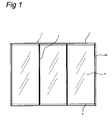
- Figure 1 shows a diagrammatic and front view of a partitioning system 1 with wall panels 5.
- the partitioning system 1 comprises in this embodiment a ceiling profile 3, a floor profile 4, a vertical support profile 2 and wall panels 5, and a profile 6a for connecting the partitioning system to another wall or partitioning system.
- the wall panels 5 are fixed, using a snap coupling, to the ceiling profile 3, which in turn is fixed to the ceiling. Furthermore, the wall panels 5 are fixed, using a snap coupling, to the floor profile 4, which in turn is fixed to the floor. The wall panels 5 are fixed, using a snap coupling, onto the vertical support profiles 2. Thus, in this embodiment, the wall panels 5 are snapped along every side.
- the partitioning system 1 will be mirror-symmetrical with respect to a mirror surface parallel to and situated in said partitioning system.
- the partitioning system 1 forms a partitioning wall between two rooms, the partition between the rooms having its own wall panels 5 on each side.
- the wall panels 5 of the adjoining rooms are installed with a gap or interspacing between them and, as a result of this gap, the resulting cavity can be filled with insulating material, such as mineral wool. In case of transparent or translucent panels, like glass panels, are used, the insulating material can be left out.
- the vertical support profiles 2 are connected to and between the ceiling profile 3 and the floor profile 4. With this arrangement, said vertical support profiles 2 are in particular positioned at the vertical side edges of the wall panels 3.
- the wall panels 5 are usually secured/fixed to the vertical support profiles 2 as well as to the floor profile 4 and the ceiling profile 3. This is, for example, as such also disclosed in NL 92.02034 , and in EP 921 245 .
- FIG 2 Depicted in figure 2 is a cross sectional view of a wall panels 5 having the coupling profiles 6 adhered to wall panel 5.
- the coupling profile 6 has a panel flange 8, and using an adhesive tape 10 it is adhered to wall panel 5.
- Using the adhesive tape makes it easy to connect the coupling profile 6 onto a wall panel, in particular to a glass panel or pane. Difficulty with a glass pane is that due to its transparent nature, the zone where the coupling profile is attached to the glass panel is and remains visible once the coupling profile is attached to the glass panel. To that end, an adhesive tape in edge region 9 is used. Furthermore, it is possible to attach the coupling profile to the panel on site. Thus, the panels are more compact when transporting them, and damage to the coupling profiles can be prevented.
- Coupling profile 6 further has a snap flange 7.
- the snap flange 7 is flexible and bendable. In this embodiment, it has a curved shape so to provide two abutments.
- the coupling profile 6 further comprises a locking lip 18. It is provided at the end of panel flange 8. It provides further stiffness to coupling profile 6.
- Figure 3 shows the coupling profile 6 with its snap flange 7 snapped into a receiving groove 11 of support profile 2.
- the width of the receiving groove 11 is indicated as S 1.
- receiving groove 11 comprises an abutment or shoulder 12 which provides an abutment surface or ledge 13 which abuts against surface 14 of snap flange 7.
- Groove 11 extends along the length of support profile 2.
- the abutment or shoulder 12 also extends in groove in longitudinal direction, thus blocking snap flange 7 in its snapped position.
- the snap flange 7 presses against the side walls of groove 11.
- the relaxed width S2 ( fig. 4 ) of the snap flange is larger than S1.
- Abutment or shoulder 12 helps keeping the snap flange 7 in groove 11.
- the locking lip 18 snaps or aligns into locking groove 19.
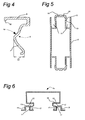
- FIG 4 shows a transverse cross section through coupling profile 6.
- the coupling profile can be made in an extrusion process. It can be made of a polymer material.
- the polymer material can be reinforced, for instance fibre reinforced.
- the material should be flexible bendable in order to allow the snap flange 7 to be snapped in groove 11 of the support profile.
- the width S2 as explained above is a little large than width S1of the groove 11 of the support profile 2 in order to allow it to be snapped in place.
- the coupling profile 6 has a snap flange 7 which in cross section view has a curve. Furthermore, it has an abutment surface 14.
- panel flange 8 and snap flange 7 are here connected via a rectangular, straight part which forms a straight surface with part of the support profile 2 when the coupling profile 6 is snapped in place.
- This enlarged cross section furthermore clearly shows locking lip 18.
- Figure 5 shows a transverse cross section through support profile 2. It is point-symmetric in the cross section. It has four grooves 11 for holding coupling profiles. Thus, a partitioning system will have two planes of wall panels with a space between then.
- Support profile 2 in this embodiment has a locking grooves 19 which allows fast installing of wall panels through a snapping action with locking lip 18 of the coupling profiles 6.
- the support profile 2 can be an extrusion profile made from polymer material, often reinforced. A sufficiently stiff profile is also produced using extruded aluminium.
- Figure 6 shows a floor profile 15 or ceiling profile 15 for the partitioning system.
- This profile 15 has two opposite grooves 11 for receiving snap flanges 6. It further comprises locking grooves 19 for the locking lip 18 of coupling profile 6.
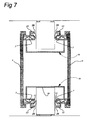
- Figure 7 shows how the profiles 15 described in figure 6 can be used to build a partitioning system.
- the floor profile 15 rests on a support structure. In this embodiment, it rests on support surfaces 16.
- Flanges 17 are provided with sealing strips 28.
- the same profile 15 is used as ceiling profile 15 in the same way as the floor profile 15. It, however, rests on support profiles 2.
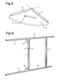
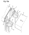
- a positioning device 20 for assisting in correct positioning of support profiles 2 with respect to floor profiles and ceiling profiles 15. It comprises two end of coupling profile 6 positioned at an angle with respect to one another. The continuation of their longitudinal axes crosses. Furthermore, it has a hand grip 21. In figure 9 , its use is shown. Two positioning devices 20 are used to keep a support profile, a floor profile 15 and a ceiling profile 15 positioned with respect to one another. Next, a wall panel 5 can be placed in free grooves 11 at the opposite side of profiles 15 and 2. Next, the positioning device 20 is removed and panels can be placed in the grooves 11 which are now available.
- Figures 10a-10c show several embodiments of coupling parts 32, 31, 30 which can be used in order to couple support profiles together at an angle. These coupling parts have ends which hook into receiving groove 11. Furthermore, they have an end which abuts inside support profiles 2.
- Figures 11a and 11b show the attachment of a further endcap profile 34.
- This endcap profile 34 comprises locking lips 35 which cooperate with the locking grooves 19 which are also used for aligning locking lips 18 of coupling profile 6.
- the endcap profile 34 comprises distance notches (or continuous rims) 36 for holding the endcap profile 34 positioned in combination with locking grooves 19/locking lips 35 without the need for further provisions on support profile 2.
- Endcap profile 34 further comprises extension 37 which allows coupling with another wall, or provides a rim 37 which can be provided with a sealing lip for resting against a door.
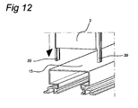
- Figure 12 shows another option for coupling a support profile 2 with a floor or ceiling profile 15. From an end part of support profile 2, a rectangular part was taken away, in such a way that part of the structure of the support profile 2 shown in figure 3 remains. Thu, two ends 39 lengthwise extending from support profile 2 remain. These ends 39 partly reach around profile 15, preventing movement of support profile 2 in a direction transverse to profile 15.
Landscapes
- Engineering & Computer Science (AREA)
- Architecture (AREA)
- Physics & Mathematics (AREA)
- Electromagnetism (AREA)
- Civil Engineering (AREA)
- Structural Engineering (AREA)
- Finishing Walls (AREA)
Priority Applications (1)
| Application Number | Priority Date | Filing Date | Title |
|---|---|---|---|
| EP09005670A EP2246495A1 (de) | 2009-04-22 | 2009-04-22 | Trennwandsystem |
Applications Claiming Priority (1)
| Application Number | Priority Date | Filing Date | Title |
|---|---|---|---|
| EP09005670A EP2246495A1 (de) | 2009-04-22 | 2009-04-22 | Trennwandsystem |
Publications (1)
| Publication Number | Publication Date |
|---|---|
| EP2246495A1 true EP2246495A1 (de) | 2010-11-03 |
Family
ID=40834497
Family Applications (1)
| Application Number | Title | Priority Date | Filing Date |
|---|---|---|---|
| EP09005670A Withdrawn EP2246495A1 (de) | 2009-04-22 | 2009-04-22 | Trennwandsystem |
Country Status (1)
| Country | Link |
|---|---|
| EP (1) | EP2246495A1 (de) |
Cited By (4)
| Publication number | Priority date | Publication date | Assignee | Title |
|---|---|---|---|---|
| ITMI20131961A1 (it) * | 2013-11-25 | 2015-05-26 | Tecno Spa | Struttura di telaio modulare |
| ITMI20131962A1 (it) * | 2013-11-25 | 2015-05-26 | Tecno Spa | Struttura di telaio modulare |
| WO2017041155A1 (pt) * | 2015-09-11 | 2017-03-16 | Bonoli José Luis | Disposição introduzida em sistema de fixação de painéis divisórios |
| WO2017065612A1 (en) | 2015-10-15 | 2017-04-20 | J.A.S.F. Beheer B.V. | Building space divider system |
Citations (8)
| Publication number | Priority date | Publication date | Assignee | Title |
|---|---|---|---|---|
| DE3825566A1 (de) * | 1988-07-28 | 1990-02-01 | Plan Object Gmbh | Profilkombination fuer staender und kaempfer der unterkonstruktion einer trennwand |
| NL9202034A (nl) | 1992-08-14 | 1994-03-01 | Flex Dev Bv | Plaatwandsysteem. |
| WO1998016699A1 (en) * | 1996-10-11 | 1998-04-23 | Dickory Rudduck | Building elements |
| US5855100A (en) * | 1998-06-12 | 1999-01-05 | Hsueh; Yi-Cheng | Partition wall |
| EP0921245A1 (de) | 1997-12-04 | 1999-06-09 | Interfinish Project B.V. | Wandpaneel für Innenwandvorrichtung und Verbindungselement dazu |
| EP1302601A1 (de) * | 2001-10-12 | 2003-04-16 | Technal | Vorrichtung für inneres Trennwandsystem mit Hohlprofildichtung |
| DE202004007841U1 (de) | 2004-05-14 | 2005-01-13 | Lindner Ag | Aufbau für eine Glastrennwand |
| DE102005002076A1 (de) | 2005-01-14 | 2006-07-20 | Bautec Mobile Trennwandsysteme Gmbh & Co. Kg | Verfahren zur Herstellung eines Glasscheibe-Metallrahmen-Bauelements, nach diesem Verfahren hergestelltes Bauelement und Vorrichtung zur Durchführung des Verfahrens |
-
2009
- 2009-04-22 EP EP09005670A patent/EP2246495A1/de not_active Withdrawn
Patent Citations (8)
| Publication number | Priority date | Publication date | Assignee | Title |
|---|---|---|---|---|
| DE3825566A1 (de) * | 1988-07-28 | 1990-02-01 | Plan Object Gmbh | Profilkombination fuer staender und kaempfer der unterkonstruktion einer trennwand |
| NL9202034A (nl) | 1992-08-14 | 1994-03-01 | Flex Dev Bv | Plaatwandsysteem. |
| WO1998016699A1 (en) * | 1996-10-11 | 1998-04-23 | Dickory Rudduck | Building elements |
| EP0921245A1 (de) | 1997-12-04 | 1999-06-09 | Interfinish Project B.V. | Wandpaneel für Innenwandvorrichtung und Verbindungselement dazu |
| US5855100A (en) * | 1998-06-12 | 1999-01-05 | Hsueh; Yi-Cheng | Partition wall |
| EP1302601A1 (de) * | 2001-10-12 | 2003-04-16 | Technal | Vorrichtung für inneres Trennwandsystem mit Hohlprofildichtung |
| DE202004007841U1 (de) | 2004-05-14 | 2005-01-13 | Lindner Ag | Aufbau für eine Glastrennwand |
| DE102005002076A1 (de) | 2005-01-14 | 2006-07-20 | Bautec Mobile Trennwandsysteme Gmbh & Co. Kg | Verfahren zur Herstellung eines Glasscheibe-Metallrahmen-Bauelements, nach diesem Verfahren hergestelltes Bauelement und Vorrichtung zur Durchführung des Verfahrens |
Cited By (6)
| Publication number | Priority date | Publication date | Assignee | Title |
|---|---|---|---|---|
| ITMI20131961A1 (it) * | 2013-11-25 | 2015-05-26 | Tecno Spa | Struttura di telaio modulare |
| ITMI20131962A1 (it) * | 2013-11-25 | 2015-05-26 | Tecno Spa | Struttura di telaio modulare |
| WO2015075586A1 (en) | 2013-11-25 | 2015-05-28 | Tecno S.P.A. | Modular frame structure |
| US9982431B2 (en) | 2013-11-25 | 2018-05-29 | Tecno S.P.A. | Modular frame structure |
| WO2017041155A1 (pt) * | 2015-09-11 | 2017-03-16 | Bonoli José Luis | Disposição introduzida em sistema de fixação de painéis divisórios |
| WO2017065612A1 (en) | 2015-10-15 | 2017-04-20 | J.A.S.F. Beheer B.V. | Building space divider system |
Similar Documents
| Publication | Publication Date | Title |
|---|---|---|
| CA1286158C (en) | Structural interface and weatherseal for structurally bonded glazing | |
| US7162842B2 (en) | Structural element system and structural elements of such system for curtain facades, facade linings, sun rooms, soundproofing walls, fair buildings and the like | |
| KR101560353B1 (ko) | 커튼 월의 차양장치 | |
| US20070251180A1 (en) | Movable walls for on-site construction | |
| US9879420B2 (en) | Partition wall system with clamping profile | |
| US20110138727A1 (en) | System and method for refurbishing an existing curtain wall | |
| EP2568094B1 (de) | Dachfenster, insbesondere ein Dachfenster, das innerhalb eines Satzes von Solarkollektoren angebracht werden kann | |
| EP2961906A1 (de) | Trennwandsystem mit plattenklemmung | |
| US10815671B2 (en) | Form panel system | |
| EP2246495A1 (de) | Trennwandsystem | |
| EP1600596B1 (de) | An einzelnen Punkten abgestützten Vorhangglasfassaden | |
| US4823533A (en) | Structural cladding apparatus | |
| RU2213832C2 (ru) | Способ построения офисных перегородок | |
| DE59901123D1 (de) | Fassadensystem für die verkleidung eines bauwerks | |
| JP2004250964A (ja) | 方立 | |
| US12371903B2 (en) | Curtain wall system accommodating wiring | |
| AU2010242547B2 (en) | Facade system | |
| KR102249516B1 (ko) | 초고층 건물용 케이블 커튼월 구조체 및 이에 적용되는 휨 보강 브라켓 | |
| CN222667042U (zh) | 一种可开启的封闭阳台结构、系统及建筑 | |
| EP3031993A1 (de) | Vorhangfassadenprofil und System | |
| JP3048836B2 (ja) | カーテンウォール用パネルユニット | |
| CN212001807U (zh) | 一种单元式幕墙系统 | |
| KR200323398Y1 (ko) | 보조창틀 | |
| AU770776B2 (en) | Method for fastening cladding panels to building frames | |
| AU2023201377A1 (en) | A wall assembly |
Legal Events
| Date | Code | Title | Description |
|---|---|---|---|
| PUAI | Public reference made under article 153(3) epc to a published international application that has entered the european phase |
Free format text: ORIGINAL CODE: 0009012 |
|
| AK | Designated contracting states |
Kind code of ref document: A1 Designated state(s): AT BE BG CH CY CZ DE DK EE ES FI FR GB GR HR HU IE IS IT LI LT LU LV MC MK MT NL NO PL PT RO SE SI SK TR |
|
| AX | Request for extension of the european patent |
Extension state: AL BA RS |
|
| STAA | Information on the status of an ep patent application or granted ep patent |
Free format text: STATUS: THE APPLICATION IS DEEMED TO BE WITHDRAWN |
|
| 18D | Application deemed to be withdrawn |
Effective date: 20110504 |