EP2246501A2 - Revêtement de sol et panneau de sol pour un sous-sol chauffé - Google Patents
Revêtement de sol et panneau de sol pour un sous-sol chauffé Download PDFInfo
- Publication number
- EP2246501A2 EP2246501A2 EP10159581A EP10159581A EP2246501A2 EP 2246501 A2 EP2246501 A2 EP 2246501A2 EP 10159581 A EP10159581 A EP 10159581A EP 10159581 A EP10159581 A EP 10159581A EP 2246501 A2 EP2246501 A2 EP 2246501A2
- Authority
- EP
- European Patent Office
- Prior art keywords
- floor
- heat
- floor covering
- layer
- conducting layer
- Prior art date
- Legal status (The legal status is an assumption and is not a legal conclusion. Google has not performed a legal analysis and makes no representation as to the accuracy of the status listed.)
- Granted
Links
Images


Classifications
-
- E—FIXED CONSTRUCTIONS
- E04—BUILDING
- E04F—FINISHING WORK ON BUILDINGS, e.g. STAIRS, FLOORS
- E04F15/00—Flooring
- E04F15/02—Flooring or floor layers composed of a number of similar elements
- E04F15/10—Flooring or floor layers composed of a number of similar elements of other materials, e.g. fibrous or chipped materials, organic plastics, magnesite tiles, hardboard, or with a top layer of other materials
- E04F15/102—Flooring or floor layers composed of a number of similar elements of other materials, e.g. fibrous or chipped materials, organic plastics, magnesite tiles, hardboard, or with a top layer of other materials of fibrous or chipped materials, e.g. bonded with synthetic resins
-
- B—PERFORMING OPERATIONS; TRANSPORTING
- B32—LAYERED PRODUCTS
- B32B—LAYERED PRODUCTS, i.e. PRODUCTS BUILT-UP OF STRATA OF FLAT OR NON-FLAT, e.g. CELLULAR OR HONEYCOMB, FORM
- B32B15/00—Layered products comprising a layer of metal
- B32B15/04—Layered products comprising a layer of metal comprising metal as the main or only constituent of a layer, which is next to another layer of the same or of a different material
- B32B15/10—Layered products comprising a layer of metal comprising metal as the main or only constituent of a layer, which is next to another layer of the same or of a different material of wood
-
- B—PERFORMING OPERATIONS; TRANSPORTING
- B32—LAYERED PRODUCTS
- B32B—LAYERED PRODUCTS, i.e. PRODUCTS BUILT-UP OF STRATA OF FLAT OR NON-FLAT, e.g. CELLULAR OR HONEYCOMB, FORM
- B32B21/00—Layered products comprising a layer of wood, e.g. wood board, veneer, wood particle board
-
- E—FIXED CONSTRUCTIONS
- E04—BUILDING
- E04F—FINISHING WORK ON BUILDINGS, e.g. STAIRS, FLOORS
- E04F15/00—Flooring
- E04F15/02—Flooring or floor layers composed of a number of similar elements
- E04F15/02194—Flooring consisting of a number of elements carried by a non-rollable common support plate or grid
-
- E—FIXED CONSTRUCTIONS
- E04—BUILDING
- E04F—FINISHING WORK ON BUILDINGS, e.g. STAIRS, FLOORS
- E04F15/00—Flooring
- E04F15/02—Flooring or floor layers composed of a number of similar elements
- E04F15/04—Flooring or floor layers composed of a number of similar elements only of wood or with a top layer of wood, e.g. with wooden or metal connecting members
- E04F15/041—Flooring or floor layers composed of a number of similar elements only of wood or with a top layer of wood, e.g. with wooden or metal connecting members with a top layer of wood in combination with a lower layer of other material
-
- E—FIXED CONSTRUCTIONS
- E04—BUILDING
- E04F—FINISHING WORK ON BUILDINGS, e.g. STAIRS, FLOORS
- E04F15/00—Flooring
- E04F15/02—Flooring or floor layers composed of a number of similar elements
- E04F15/10—Flooring or floor layers composed of a number of similar elements of other materials, e.g. fibrous or chipped materials, organic plastics, magnesite tiles, hardboard, or with a top layer of other materials
- E04F15/105—Flooring or floor layers composed of a number of similar elements of other materials, e.g. fibrous or chipped materials, organic plastics, magnesite tiles, hardboard, or with a top layer of other materials of organic plastics with or without reinforcements or filling materials
-
- E—FIXED CONSTRUCTIONS
- E04—BUILDING
- E04F—FINISHING WORK ON BUILDINGS, e.g. STAIRS, FLOORS
- E04F15/00—Flooring
- E04F15/18—Separately-laid insulating layers; Other additional insulating measures; Floating floors
- E04F15/181—Insulating layers integrally formed with the flooring or the flooring elements
-
- F—MECHANICAL ENGINEERING; LIGHTING; HEATING; WEAPONS; BLASTING
- F24—HEATING; RANGES; VENTILATING
- F24D—DOMESTIC- OR SPACE-HEATING SYSTEMS, e.g. CENTRAL HEATING SYSTEMS; DOMESTIC HOT-WATER SUPPLY SYSTEMS; ELEMENTS OR COMPONENTS THEREFOR
- F24D3/00—Hot-water central heating systems
- F24D3/12—Tube and panel arrangements for ceiling, wall, or underfloor heating
- F24D3/14—Tube and panel arrangements for ceiling, wall, or underfloor heating incorporated in a ceiling, wall or floor
-
- E—FIXED CONSTRUCTIONS
- E04—BUILDING
- E04F—FINISHING WORK ON BUILDINGS, e.g. STAIRS, FLOORS
- E04F2290/00—Specially adapted covering, lining or flooring elements not otherwise provided for
- E04F2290/04—Specially adapted covering, lining or flooring elements not otherwise provided for for insulation or surface protection, e.g. against noise, impact or fire
- E04F2290/041—Specially adapted covering, lining or flooring elements not otherwise provided for for insulation or surface protection, e.g. against noise, impact or fire against noise
- E04F2290/043—Specially adapted covering, lining or flooring elements not otherwise provided for for insulation or surface protection, e.g. against noise, impact or fire against noise with a bottom layer for sound insulation
-
- Y—GENERAL TAGGING OF NEW TECHNOLOGICAL DEVELOPMENTS; GENERAL TAGGING OF CROSS-SECTIONAL TECHNOLOGIES SPANNING OVER SEVERAL SECTIONS OF THE IPC; TECHNICAL SUBJECTS COVERED BY FORMER USPC CROSS-REFERENCE ART COLLECTIONS [XRACs] AND DIGESTS
- Y02—TECHNOLOGIES OR APPLICATIONS FOR MITIGATION OR ADAPTATION AGAINST CLIMATE CHANGE
- Y02B—CLIMATE CHANGE MITIGATION TECHNOLOGIES RELATED TO BUILDINGS, e.g. HOUSING, HOUSE APPLIANCES OR RELATED END-USER APPLICATIONS
- Y02B30/00—Energy efficient heating, ventilation or air conditioning [HVAC]
Definitions
- the invention relates to a floor covering, in particular for a heated substrate, having a multilayer structure, comprising a plurality of interconnected floor panels, wherein the floor panels a substantially made of a wood material, a plastic and / or a wood-plastic mixture carrier plate and a have disposed thereon coating and wherein an upper layer formed by the coating of the floor panels is provided. Furthermore, the invention relates to a floor panel, preferably for a floor covering of the type mentioned, with a substantially made of a wood material, a plastic and / or a wood-plastic mixture carrier plate and a coating disposed thereon.
- Laminate panels usually have a carrier plate, which is provided with a decor.
- the decor can consist of a resin-impregnated decorative paper.
- hard particles such as corundum or other mineral materials may be included to protect the surface against wear, especially abrasion and scratching.
- a so-called overlay may be provided on the decor.
- Such an overlay also has at least one resin-soaked paper which is transparent, however.
- the resin in particular melamine or melamine / urea resins are used.
- the overlay may also have hard particles of the type mentioned.
- the decor and the overlay are permanently connected by heat and pressure.
- the panels can also be printed directly with a decor, wherein on the decor a transparent sealing lacquer or an overlay of the type described above is provided. If necessary, a primer layer can be provided between the printed decor and the carrier plate, which, however, can be regarded as part of the decoration.
- Corresponding floor coverings are versatile and have a high durability.
- the use of floor panels in rooms with a heated floor in the form of underfloor heating is also possible. However, this limits the energy efficiency of underfloor heating so that a slightly higher energy consumption can be expected.
- the support plates of the floor panels are regularly made of wood materials, plastic or a mixture of wood and plastic.
- fiberboards are used as carrier plates, which are mostly medium density fibreboard (MDF) or high density fiberboard (HDF).
- MDF medium density fibreboard
- HDF high density fiberboard
- the Support plates have due to the materials used a limited thermal conductivity, so that the heat transfer is limited by the floor heating in the room to be heated.
- the heat transport in the room to be heated is also limited by the fact that the floor panels must not be exposed to high temperatures.
- the panels with carrier plates made of a wood material in the case of excessively high temperatures, the panels over-dry, which can lead to undesired joint formation and / or to breaks in the surface layers.
- the present invention is therefore based on the technical problem of proposing a floor covering and a floor panel respectively of the type mentioned above and described in more detail above, which allows a reduction in energy consumption when applied to a heated surface.
- Mineral and / or metallic materials have in comparison to wood materials and / or plastics higher thermal conductivity ⁇ on.
- the mineral components are in particular sand ( ⁇ 1,4 W / mK), crystalline metamorphic rocks ( ⁇ 3,5 W / mK), such as granite or basalt, sedimentary rocks ( ⁇ 2,3 W / mK), like sandstone or shell limestone, as well as ceramic materials in question.
- As metallic components pure metals, such as copper ( ⁇ 380 W / mK) or aluminum ( ⁇ 200 W / mK), or alloys such as steel ( ⁇ 60 W / mK) are suitable.
- the overall thermal conductivity of the floor covering improves.
- a corresponding component is provided in a layer below the coating of the floor panels and thus below the upper layer of the floor covering.
- the upper layer of the floor covering as well as the floor panels is understood to mean the coating provided on the carrier plate, which may consist of one layer or a plurality of separate but relatively thin layers, such as decor, overlay and / or sealing lacquer.
- the coating may, as described above, have a mineral component in the form of hard particles, which essentially serves to reduce the abrasion of the floor covering. Since the mineral component coating is very thin and is provided at or near the top of the floor covering, the coating does not appreciably improve the heat transfer properties of the floor panels.
- the heat-conducting layer is inventively provided below the coating and thus arranged at a shorter distance to the ground.
- the temperature profile of the substrate can be made uniform and, as a result, the resistance that the floor covering opposes to heat transport can be reduced.
- heating elements in the form of water-flowed pipes are provided, which can be arranged in a screed.
- heating elements in the form of electrical conductors into consideration which are laid on the substrate or the screed. Regardless of the type of heating elements, these are routinely laid serpentine. Therefore, the higher the temperature above the heating element and the greater the slower the heat is dissipated to the room to be heated. If this is not done fast enough, it is called a heat accumulation. In contrast, lower temperatures prevail between the individual sections of the heating element. Due to this temperature profile, the heat is not emitted evenly from the floor covering to the room, but reinforced by the areas of the floor covering arranged immediately above the heating elements.
- the invention has recognized that the heat-conducting layer of the floor covering not only improves the heat conduction perpendicular to the floor covering, but also parallel to the floor covering. Thereby, a more uniform temperature profile of the substrate is achieved, because the heat is transported from an area above a portion of the heating element into an area between two sections of the heating element. This results in an overall increase in the heat transport through the floor covering in the heated Space that is further increased by the better heat transfer perpendicular to the floor covering. Ultimately, an improvement of the heat transport in a plane parallel to the floor covering and in a direction perpendicular thereto is achieved.
- the heat-conducting layer is formed by the support plates of the floor panels. This is useful because the support plate is relatively thick and so the heat transfer can be significantly improved.
- the support plate is provided relatively close to the ground, which is advantageous for the equalization of the temperature profile parallel to the floor covering.
- the mineral and / or metallic component can be distributed more or less uniformly throughout the carrier plate. But it can also be provided that the mineral and / or metallic component is preferably provided in the lower region of the support plate, so that the temperature profile can be made even closer to the ground of the floor covering in a plane parallel to the ground or to the floor covering.
- the carrier plate is formed substantially from pressed wood particles and / or wood fibers, they are first spread to a so-called cake with the desired layer thickness prior to pressing, whereby the mineral and / or metallic component can also be introduced into the cake. If the mineral and / or metallic component consists of smaller particles, these can be scattered into the cake.
- the heat-conducting layer on the upper layer of the floor covering or the coating of the floor panels opposite side of the support plate is arranged.
- the heat-conducting layer is therefore arranged below the support plate and thus provided in the installed state very close to the ground, which is conducive to a homogenization of the temperature profile.
- the thermally conductive layer may be formed, for example, as provided below the support plate layer of the floor panels. Then the heat-conducting layer is integrated into the floor panels, which simplifies laying. There are no additional components or additional process steps for laying the floor covering required. Preferably, the heat-conducting layer is directly connected to the underside of the support plate, whereby the structure of the floor panels is simplified.
- the heat-conducting layer is formed by the impact sound insulation, the backslash and / or the Gegenzug harsh the floor panels. This is achieved, for example, by introducing the mineral and / or metallic component into a layer serving to provide impact sound insulation, a backing layer or a backsheet.
- a counteracting layer is understood as meaning a laminate coating provided on the underside of the floor panel and / or the carrier plate with at least one resin-impregnated paper.
- the counteracting layer serves to balance the tension to the resin-impregnated decor paper provided on the upper side of the floor panels and possibly to the so-called overlay arranged thereon.
- a backslash will also equalize the tension provided with direct-coated panels on the underside of the panel and / or underside of the support plate. The backslash is usually obtained by a paint job.
- an adhesive layer may be provided for substantially full-surface sticking of the floor panels of the floor covering to the substrate.
- the heat-conducting layer is formed by the adhesive layer. This is done in a simple manner in that the mineral and / or metallic component is introduced into the adhesive in finely divided form prior to the application of the adhesive. But it can also be provided that the mineral and / or metallic component is applied before or after the distribution of the adhesive.
- the adhesive surrounds the mineral and / or metallic component, so that as a result of the curing, an adhesive layer comprising the adhesive and the mineral and / or metallic component is formed.
- the mineral and / or metallic component may be provided in the form of a disperse phase in the heat-conducting layer.
- the mineral and / or metallic component is thus provided finely distributed in a so-called continuous phase, wherein the distribution can be homogeneous or inhomogeneous.
- the continuous Phase can be formed for example by the glued wood fibers of a carrier plate, the adhesive of an adhesive layer or the impact sound material of a footfall sound insulation.
- the mineral and / or metallic component may be formed as a large-area element.
- the mineral and / or metallic component can be provided as a woven fabric, fleece, grid or film in the heat-conducting layer.
- a grid structure may be preferred when the heat-conducting layer is formed by the floor panels, i. the mineral and / or metallic component is part of the floor panels.
- Tissues or nonwovens are also suitable, for example, for incorporation into an adhesive layer.
- the heat-conducting layer is formed as a vapor barrier. Both functions are then combined in one shift.
- the vapor barrier can be designed for this purpose as a metal foil. But it can also be used with plastic coated metal foil or a plastic film, in which the mineral and / or metallic component is introduced.
- the vapor barrier is in any case an integral part of the floor panels, so that the heat-conducting layer of the floor covering is formed when laying the floor panels, without the need for further work steps should be performed.
- the support plate has a density of at least 950 kg / m 3 and / or is formed from a high-density fiberboard (HDF).
- HDF high-density fiberboard
- the heat transfer of the floor covering is improved by the use of flat floor panels.
- the floor panels therefore have a thickness of at most 6 mm, preferably at most 5 mm, in particular at most 4 mm.
- the floor covering 1 consists of a plurality of floor panels 2, which are connected to each other via known from the prior art connection and / or locking profiles.
- the connection or locking profiles are shown only schematically, since the nature of the connection or locking profiles is of minor importance in the present case.
- the floor panels 2 are rectangular and connected both at their long and at their short narrow edges with other floor panels 2, the floor covering 1.
- the floor panels 2 are so-called laminate panels with a corresponding, not shown in detail layer structure.
- a pad 3 is provided below the floor panels 1, a pad 3 is provided below the floor panels 1.
- the floor covering 1 is provided on a heatable substrate U, wherein this has an upper screed layer E, in which a tube R is laid serpentine, which can be flowed through by a heat transfer medium, which in the present case is hot water.
- the tube R has parallel to each other extending portions which are spaced from each other by a distance a.
- the substrate U above the mutually parallel pipe sections heats up more than between these pipe sections.
- a conventional floor covering is provided on the ground, the result is a temperature profile, as shown schematically in the Fig. 2 shown graphical plot is shown as a dashed line.
- the temperature of the substrate is applied against the distance from one of the parallel pipe sections of the floor heating in a direction perpendicular to this pipe section and parallel to the floor covering.
- the temperature is maximum at a minimum and a minimum therebetween, and the difference between the maximum and the minimum temperature is significant.
- the temperature above the parallel pipe pieces is maximum while the temperature therebetween is minimum.
- the difference between the maximum and the minimum temperature is this Temperature profile significantly lower.
- the temperature of the subsurface is more evenly distributed because the mineral and / or metallic component of the thermally conductive layer conducts heat from areas above the parallel pipe sections to areas therebetween thus contributing to temperature balance of the substrate.
- This also preferably results in a higher average temperature of the substrate and / or the floor covering, so that the temperature difference between the substrate and / or floor covering on the one hand and the room air on the other hand is greater overall and thus the output to the room air heat flow is increased.
- FIG. 3 is a detail of the floor covering 1 from the Fig. 1 shown.
- the floor panels 2 have a support plate 4 made of a high-density fiberboard (HDF).
- the support plate 4 simultaneously forms the heat-conducting layer 5 of the floor covering 1.
- mineral particles 6 are uniformly distributed in the support plate 4. The proportion of mineral particles 6 is large enough to significantly improve the overall thermal conduction of the support plate 4.
- a coating 7 is provided which forms the upper layer 8 of the floor covering 1 and has two different layers.
- a decorative layer 9 made of a melamine resin, in which a decor paper is provided.
- an overlay 10 is arranged, which also consists of a paper impregnated with melamine resin, but additionally has finely divided, not shown in detail corundum particles.
- a Gegenzug Mrs 11 made of a resin and at least one embedded therein special paper.
- an insulating layer 12 of the floor covering 1 is provided, which is not connected in the illustrated embodiment with the floor panel 2 and placed directly on the substrate U.
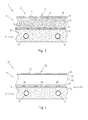
- the Indian Fig. 4 Floor covering 21 shown comprises directly painted floor panels 22. These also have a support plate 24 made of a high-density fiberboard (HDF). At the top of the support plate 24, a coating 27 is provided which forms the upper layer 28 of the floor covering 21 and consists of a decorative layer 29 and a protective layer 30 containing hard particles. On the underside of the support plate 14, a backslash 33 is provided in the form of a paint job.
- HDF high-density fiberboard
- the floor panels 22 in the Fig. 4 shown floor coverings 21 are bonded by means of an adhesive layer 34 on the substrate U.
- the substrate U in turn has a screed layer E with a water-flowed pipe R laid therein.
- the adhesive layer 34 serves in addition to the bonding of the floor panels 22 on the substrate U as a heat-conducting layer 25 of the floor covering 21, since the adhesive layer 34 has an adhesive with a finely dispersed mineral component 26, wherein it is sand.
- the Indian Fig. 5 shown floor covering 41 comprises floor panels 42 with a support plate on which a Coating 47 is provided, which is a laminate coating.
- the laminate coating forms the top layer of the floor covering 48 and has a decorative layer 49 with a resin-soaked decorative paper and an overlay 50 thereon, which comprises a resin-impregnated transparent paper.
- a Gegenzug für 51 is provided, which is not formed as a laminate coating, but as a metal foil, which is the metallic component 46 of the heat-conducting layer 45.
- the counteracting layer 51 or the heat-conducting layer 45 lies directly on the substrate U.
- the Indian Fig. 6 Floor covering 61 shown comprises floor panels 62, which has a coating 67 as the upper layer 68 of the floor covering 61 from a decorative layer 69 connected to the carrier plate 64 and an overlay 70 arranged thereon.
- the floor panel 62 has a backslash 73 and a footfall sound insulation 75 integrated into the floor panel 62.
- the impact sound insulation 75 contains a metallic component 66 in the form of finely distributed metallic chips, so that the impact sound insulation 75 forms the heat-conducting layer 65 of the floor covering 61.
Landscapes
- Engineering & Computer Science (AREA)
- Architecture (AREA)
- Civil Engineering (AREA)
- Structural Engineering (AREA)
- Life Sciences & Earth Sciences (AREA)
- Wood Science & Technology (AREA)
- Physics & Mathematics (AREA)
- Thermal Sciences (AREA)
- Chemical & Material Sciences (AREA)
- Combustion & Propulsion (AREA)
- Mechanical Engineering (AREA)
- General Engineering & Computer Science (AREA)
- Floor Finish (AREA)
- Laminated Bodies (AREA)
Priority Applications (1)
| Application Number | Priority Date | Filing Date | Title |
|---|---|---|---|
| PL10159581T PL2246501T3 (pl) | 2009-04-22 | 2010-04-12 | Wykładzina podłogowa i panel podłogowy dla ogrzewanego podłoża |
Applications Claiming Priority (2)
| Application Number | Priority Date | Filing Date | Title |
|---|---|---|---|
| DE200910018181 DE102009018181A1 (de) | 2009-04-22 | 2009-04-22 | Fußbodenbelag und Fußbodenpaneel für einen beheizten Untergrund |
| DE102009032806A DE102009032806A1 (de) | 2009-07-10 | 2009-07-10 | Fußbodenbelag und Fußbodenpaneel für einen beheizten Untergrund |
Publications (3)
| Publication Number | Publication Date |
|---|---|
| EP2246501A2 true EP2246501A2 (fr) | 2010-11-03 |
| EP2246501A3 EP2246501A3 (fr) | 2013-05-29 |
| EP2246501B1 EP2246501B1 (fr) | 2017-01-25 |
Family
ID=42549434
Family Applications (1)
| Application Number | Title | Priority Date | Filing Date |
|---|---|---|---|
| EP10159581.7A Active EP2246501B1 (fr) | 2009-04-22 | 2010-04-12 | Revêtement de sol et panneau de sol pour un sous-sol chauffé |
Country Status (4)
| Country | Link |
|---|---|
| EP (1) | EP2246501B1 (fr) |
| ES (1) | ES2621779T3 (fr) |
| HU (1) | HUE032731T2 (fr) |
| PL (1) | PL2246501T3 (fr) |
Cited By (2)
| Publication number | Priority date | Publication date | Assignee | Title |
|---|---|---|---|---|
| CN103790339A (zh) * | 2014-01-29 | 2014-05-14 | 贾留欣 | 一种木塑地板及其制备方法 |
| EP2848748A1 (fr) * | 2013-09-13 | 2015-03-18 | Erich Krause | Lame multicouches et utilisation de la lame multicouches |
Family Cites Families (6)
| Publication number | Priority date | Publication date | Assignee | Title |
|---|---|---|---|---|
| FR2341021A1 (fr) * | 1976-02-13 | 1977-09-09 | Bat Applic Revetements Plastiq | Perfectionnement aux revetements de sol en matiere plastique |
| DE10151614C1 (de) * | 2001-10-23 | 2003-04-24 | Kaindl Wals M | Paneel mit schallverbessernder Schicht nebst Herstellungsverfahren |
| EP1362968A1 (fr) * | 2002-05-17 | 2003-11-19 | Fritz Egger GmbH & Co | Plancher avec isolation acoustique et fonction adhésive intégrales |
| DE10354789B4 (de) * | 2003-11-21 | 2011-12-15 | hülsta-werke Hüls GmbH & Co. KG. | Paneel und Belag |
| DE102006048471B4 (de) * | 2006-10-11 | 2008-09-04 | Kronotec Ag | Bodenpaneel |
| EP1958765A1 (fr) * | 2007-02-15 | 2008-08-20 | Julien Waumans | Sol pour installations sportives |
-
2010
- 2010-04-12 ES ES10159581.7T patent/ES2621779T3/es active Active
- 2010-04-12 EP EP10159581.7A patent/EP2246501B1/fr active Active
- 2010-04-12 PL PL10159581T patent/PL2246501T3/pl unknown
- 2010-04-12 HU HUE10159581A patent/HUE032731T2/en unknown
Non-Patent Citations (1)
| Title |
|---|
| None |
Cited By (2)
| Publication number | Priority date | Publication date | Assignee | Title |
|---|---|---|---|---|
| EP2848748A1 (fr) * | 2013-09-13 | 2015-03-18 | Erich Krause | Lame multicouches et utilisation de la lame multicouches |
| CN103790339A (zh) * | 2014-01-29 | 2014-05-14 | 贾留欣 | 一种木塑地板及其制备方法 |
Also Published As
| Publication number | Publication date |
|---|---|
| EP2246501B1 (fr) | 2017-01-25 |
| HUE032731T2 (en) | 2017-10-30 |
| ES2621779T3 (es) | 2017-07-05 |
| EP2246501A3 (fr) | 2013-05-29 |
| PL2246501T3 (pl) | 2017-07-31 |
Similar Documents
| Publication | Publication Date | Title |
|---|---|---|
| EP2272667B1 (fr) | Plaque en matière dérivée du bois et son procédé de fabrication | |
| EP1938963B1 (fr) | Panneau de sol | |
| DE102009031954A1 (de) | Verfahren zur Anbringung von Kantenbändern auf Schmalflächen von insbesondere plattenförmigen Werkstücken und auf diese Weise erhältliche Werkstücke | |
| EP3144449B1 (fr) | Élement de construction en forme de plaque | |
| DE19944399A1 (de) | Fussbodenelement mit klangarmer Trägerschicht | |
| EP1864552A2 (fr) | Dispositif de chauffage de surface | |
| EP2519783A1 (fr) | Dispositif de thermorégulation d'une pièce | |
| DE102012001557A1 (de) | Plattenförmiges Element für Fußbodenheizungen | |
| WO2017009011A1 (fr) | Procédé de fabrication d'un stratifié composé d'une plaque de support et d'un papier décoratif | |
| DE102005029051A1 (de) | Wärmeleitvorrichtung für eine Fußboden-, Wand- oder Deckenheizung | |
| WO2020259736A1 (fr) | Élément de construction en forme de plaque et son procédé de fabrication | |
| DE102009032153A1 (de) | Verfahren zur Herstellung einer Schichtstoffverbundplatte | |
| EP2246501B1 (fr) | Revêtement de sol et panneau de sol pour un sous-sol chauffé | |
| DE102009054699B4 (de) | Verfahren zum Herstellen einer Heiztafel | |
| EP3587108B1 (fr) | Panneau sandwich contrecollé | |
| DE102009032806A1 (de) | Fußbodenbelag und Fußbodenpaneel für einen beheizten Untergrund | |
| DE102009018181A1 (de) | Fußbodenbelag und Fußbodenpaneel für einen beheizten Untergrund | |
| EP2703741A1 (fr) | Agrégat de plaques et procédé de fabrication dýun agrégat de plaques | |
| EP3892062A1 (fr) | Chauffage infrarouge par les murs protégé pourvu de tissu chauffant souple | |
| EP3568298B1 (fr) | Procédé de fabrication d'un stratifié pour un revêtement de sol | |
| DE102017007995B4 (de) | Modulares Plattenelement zum Erstellen einer Wandheizung und System zum modularen Erstellen einer Wand aus Wandheizungselementen | |
| EP4005341B1 (fr) | Chauffage plan à induction | |
| WO2008141634A1 (fr) | Panneau composite | |
| EP1005980A1 (fr) | Ligne de production d'éléments muraux et procédé pour le collage de ces éléments sur leurs deux faces | |
| EP3216941B1 (fr) | Plaque de revêtement de sol et revêtement de sol |
Legal Events
| Date | Code | Title | Description |
|---|---|---|---|
| PUAI | Public reference made under article 153(3) epc to a published international application that has entered the european phase |
Free format text: ORIGINAL CODE: 0009012 |
|
| AK | Designated contracting states |
Kind code of ref document: A2 Designated state(s): AT BE BG CH CY CZ DE DK EE ES FI FR GB GR HR HU IE IS IT LI LT LU LV MC MK MT NL NO PL PT RO SE SI SK SM TR |
|
| PUAL | Search report despatched |
Free format text: ORIGINAL CODE: 0009013 |
|
| AK | Designated contracting states |
Kind code of ref document: A3 Designated state(s): AT BE BG CH CY CZ DE DK EE ES FI FR GB GR HR HU IE IS IT LI LT LU LV MC MK MT NL NO PL PT RO SE SI SK SM TR |
|
| RIC1 | Information provided on ipc code assigned before grant |
Ipc: B32B 21/00 20060101ALI20130419BHEP Ipc: E04F 15/18 20060101ALI20130419BHEP Ipc: F24D 3/14 20060101ALI20130419BHEP Ipc: E04F 15/02 20060101AFI20130419BHEP Ipc: E04F 15/10 20060101ALI20130419BHEP Ipc: B32B 15/10 20060101ALI20130419BHEP |
|
| 17P | Request for examination filed |
Effective date: 20131129 |
|
| RBV | Designated contracting states (corrected) |
Designated state(s): AT BE BG CH CY CZ DE DK EE ES FI FR GB GR HR HU IE IS IT LI LT LU LV MC MK MT NL NO PL PT RO SE SI SK SM TR |
|
| RAP1 | Party data changed (applicant data changed or rights of an application transferred) |
Owner name: FRITZ EGGER GMBH & CO. OG |
|
| 17Q | First examination report despatched |
Effective date: 20151117 |
|
| GRAP | Despatch of communication of intention to grant a patent |
Free format text: ORIGINAL CODE: EPIDOSNIGR1 |
|
| INTG | Intention to grant announced |
Effective date: 20160822 |
|
| GRAS | Grant fee paid |
Free format text: ORIGINAL CODE: EPIDOSNIGR3 |
|
| GRAA | (expected) grant |
Free format text: ORIGINAL CODE: 0009210 |
|
| AK | Designated contracting states |
Kind code of ref document: B1 Designated state(s): AT BE BG CH CY CZ DE DK EE ES FI FR GB GR HR HU IE IS IT LI LT LU LV MC MK MT NL NO PL PT RO SE SI SK SM TR |
|
| REG | Reference to a national code |
Ref country code: GB Ref legal event code: FG4D Free format text: NOT ENGLISH |
|
| REG | Reference to a national code |
Ref country code: CH Ref legal event code: EP |
|
| REG | Reference to a national code |
Ref country code: AT Ref legal event code: REF Ref document number: 864235 Country of ref document: AT Kind code of ref document: T Effective date: 20170215 |
|
| REG | Reference to a national code |
Ref country code: IE Ref legal event code: FG4D Free format text: LANGUAGE OF EP DOCUMENT: GERMAN |
|
| REG | Reference to a national code |
Ref country code: DE Ref legal event code: R096 Ref document number: 502010013104 Country of ref document: DE |
|
| REG | Reference to a national code |
Ref country code: CH Ref legal event code: NV Representative=s name: SCHMAUDER AND PARTNER AG PATENT- UND MARKENANW, CH |
|
| REG | Reference to a national code |
Ref country code: NL Ref legal event code: FP |
|
| REG | Reference to a national code |
Ref country code: SE Ref legal event code: TRGR Ref country code: FR Ref legal event code: PLFP Year of fee payment: 8 |
|
| REG | Reference to a national code |
Ref country code: EE Ref legal event code: FG4A Ref document number: E013557 Country of ref document: EE Effective date: 20170407 |
|
| REG | Reference to a national code |
Ref country code: LT Ref legal event code: MG4D |
|
| REG | Reference to a national code |
Ref country code: ES Ref legal event code: FG2A Ref document number: 2621779 Country of ref document: ES Kind code of ref document: T3 Effective date: 20170705 |
|
| PG25 | Lapsed in a contracting state [announced via postgrant information from national office to epo] |
Ref country code: LT Free format text: LAPSE BECAUSE OF FAILURE TO SUBMIT A TRANSLATION OF THE DESCRIPTION OR TO PAY THE FEE WITHIN THE PRESCRIBED TIME-LIMIT Effective date: 20170125 Ref country code: NO Free format text: LAPSE BECAUSE OF FAILURE TO SUBMIT A TRANSLATION OF THE DESCRIPTION OR TO PAY THE FEE WITHIN THE PRESCRIBED TIME-LIMIT Effective date: 20170425 Ref country code: IS Free format text: LAPSE BECAUSE OF FAILURE TO SUBMIT A TRANSLATION OF THE DESCRIPTION OR TO PAY THE FEE WITHIN THE PRESCRIBED TIME-LIMIT Effective date: 20170525 Ref country code: GR Free format text: LAPSE BECAUSE OF FAILURE TO SUBMIT A TRANSLATION OF THE DESCRIPTION OR TO PAY THE FEE WITHIN THE PRESCRIBED TIME-LIMIT Effective date: 20170426 Ref country code: HR Free format text: LAPSE BECAUSE OF FAILURE TO SUBMIT A TRANSLATION OF THE DESCRIPTION OR TO PAY THE FEE WITHIN THE PRESCRIBED TIME-LIMIT Effective date: 20170125 Ref country code: FI Free format text: LAPSE BECAUSE OF FAILURE TO SUBMIT A TRANSLATION OF THE DESCRIPTION OR TO PAY THE FEE WITHIN THE PRESCRIBED TIME-LIMIT Effective date: 20170125 |
|
| PG25 | Lapsed in a contracting state [announced via postgrant information from national office to epo] |
Ref country code: LV Free format text: LAPSE BECAUSE OF FAILURE TO SUBMIT A TRANSLATION OF THE DESCRIPTION OR TO PAY THE FEE WITHIN THE PRESCRIBED TIME-LIMIT Effective date: 20170125 Ref country code: PT Free format text: LAPSE BECAUSE OF FAILURE TO SUBMIT A TRANSLATION OF THE DESCRIPTION OR TO PAY THE FEE WITHIN THE PRESCRIBED TIME-LIMIT Effective date: 20170525 Ref country code: BG Free format text: LAPSE BECAUSE OF FAILURE TO SUBMIT A TRANSLATION OF THE DESCRIPTION OR TO PAY THE FEE WITHIN THE PRESCRIBED TIME-LIMIT Effective date: 20170425 |
|
| REG | Reference to a national code |
Ref country code: SK Ref legal event code: T3 Ref document number: E 23932 Country of ref document: SK |
|
| REG | Reference to a national code |
Ref country code: DE Ref legal event code: R097 Ref document number: 502010013104 Country of ref document: DE |
|
| REG | Reference to a national code |
Ref country code: HU Ref legal event code: AG4A Ref document number: E032731 Country of ref document: HU |
|
| PG25 | Lapsed in a contracting state [announced via postgrant information from national office to epo] |
Ref country code: RO Free format text: LAPSE BECAUSE OF FAILURE TO SUBMIT A TRANSLATION OF THE DESCRIPTION OR TO PAY THE FEE WITHIN THE PRESCRIBED TIME-LIMIT Effective date: 20170125 |
|
| PG25 | Lapsed in a contracting state [announced via postgrant information from national office to epo] |
Ref country code: SM Free format text: LAPSE BECAUSE OF FAILURE TO SUBMIT A TRANSLATION OF THE DESCRIPTION OR TO PAY THE FEE WITHIN THE PRESCRIBED TIME-LIMIT Effective date: 20170125 Ref country code: DK Free format text: LAPSE BECAUSE OF FAILURE TO SUBMIT A TRANSLATION OF THE DESCRIPTION OR TO PAY THE FEE WITHIN THE PRESCRIBED TIME-LIMIT Effective date: 20170125 |
|
| PLBE | No opposition filed within time limit |
Free format text: ORIGINAL CODE: 0009261 |
|
| STAA | Information on the status of an ep patent application or granted ep patent |
Free format text: STATUS: NO OPPOSITION FILED WITHIN TIME LIMIT |
|
| 26N | No opposition filed |
Effective date: 20171026 |
|
| REG | Reference to a national code |
Ref country code: IE Ref legal event code: MM4A |
|
| PG25 | Lapsed in a contracting state [announced via postgrant information from national office to epo] |
Ref country code: MC Free format text: LAPSE BECAUSE OF FAILURE TO SUBMIT A TRANSLATION OF THE DESCRIPTION OR TO PAY THE FEE WITHIN THE PRESCRIBED TIME-LIMIT Effective date: 20170125 |
|
| PG25 | Lapsed in a contracting state [announced via postgrant information from national office to epo] |
Ref country code: SI Free format text: LAPSE BECAUSE OF FAILURE TO SUBMIT A TRANSLATION OF THE DESCRIPTION OR TO PAY THE FEE WITHIN THE PRESCRIBED TIME-LIMIT Effective date: 20170125 Ref country code: LU Free format text: LAPSE BECAUSE OF NON-PAYMENT OF DUE FEES Effective date: 20170412 |
|
| REG | Reference to a national code |
Ref country code: FR Ref legal event code: PLFP Year of fee payment: 9 |
|
| PG25 | Lapsed in a contracting state [announced via postgrant information from national office to epo] |
Ref country code: IE Free format text: LAPSE BECAUSE OF NON-PAYMENT OF DUE FEES Effective date: 20170412 |
|
| PG25 | Lapsed in a contracting state [announced via postgrant information from national office to epo] |
Ref country code: MT Free format text: LAPSE BECAUSE OF FAILURE TO SUBMIT A TRANSLATION OF THE DESCRIPTION OR TO PAY THE FEE WITHIN THE PRESCRIBED TIME-LIMIT Effective date: 20170125 |
|
| PG25 | Lapsed in a contracting state [announced via postgrant information from national office to epo] |
Ref country code: CY Free format text: LAPSE BECAUSE OF NON-PAYMENT OF DUE FEES Effective date: 20170125 |
|
| PG25 | Lapsed in a contracting state [announced via postgrant information from national office to epo] |
Ref country code: MK Free format text: LAPSE BECAUSE OF FAILURE TO SUBMIT A TRANSLATION OF THE DESCRIPTION OR TO PAY THE FEE WITHIN THE PRESCRIBED TIME-LIMIT Effective date: 20170125 |
|
| PG25 | Lapsed in a contracting state [announced via postgrant information from national office to epo] |
Ref country code: TR Free format text: LAPSE BECAUSE OF FAILURE TO SUBMIT A TRANSLATION OF THE DESCRIPTION OR TO PAY THE FEE WITHIN THE PRESCRIBED TIME-LIMIT Effective date: 20170125 |
|
| PGFP | Annual fee paid to national office [announced via postgrant information from national office to epo] |
Ref country code: EE Payment date: 20250320 Year of fee payment: 16 |
|
| PGFP | Annual fee paid to national office [announced via postgrant information from national office to epo] |
Ref country code: CZ Payment date: 20250228 Year of fee payment: 16 |
|
| PGFP | Annual fee paid to national office [announced via postgrant information from national office to epo] |
Ref country code: SK Payment date: 20250228 Year of fee payment: 16 |
|
| PGFP | Annual fee paid to national office [announced via postgrant information from national office to epo] |
Ref country code: NL Payment date: 20250425 Year of fee payment: 16 |
|
| PGFP | Annual fee paid to national office [announced via postgrant information from national office to epo] |
Ref country code: DE Payment date: 20250424 Year of fee payment: 16 Ref country code: PL Payment date: 20250403 Year of fee payment: 16 |
|
| PGFP | Annual fee paid to national office [announced via postgrant information from national office to epo] |
Ref country code: GB Payment date: 20250424 Year of fee payment: 16 Ref country code: ES Payment date: 20250528 Year of fee payment: 16 |
|
| PGFP | Annual fee paid to national office [announced via postgrant information from national office to epo] |
Ref country code: HU Payment date: 20250307 Year of fee payment: 16 |
|
| PGFP | Annual fee paid to national office [announced via postgrant information from national office to epo] |
Ref country code: BE Payment date: 20250425 Year of fee payment: 16 Ref country code: IT Payment date: 20250429 Year of fee payment: 16 |
|
| PGFP | Annual fee paid to national office [announced via postgrant information from national office to epo] |
Ref country code: FR Payment date: 20250424 Year of fee payment: 16 |
|
| PGFP | Annual fee paid to national office [announced via postgrant information from national office to epo] |
Ref country code: CH Payment date: 20250501 Year of fee payment: 16 |
|
| PGFP | Annual fee paid to national office [announced via postgrant information from national office to epo] |
Ref country code: AT Payment date: 20250425 Year of fee payment: 16 |
|
| PGFP | Annual fee paid to national office [announced via postgrant information from national office to epo] |
Ref country code: SE Payment date: 20250425 Year of fee payment: 16 |