EP2246502A2 - Elévateur doté d'une douille de réception adaptable - Google Patents
Elévateur doté d'une douille de réception adaptable Download PDFInfo
- Publication number
- EP2246502A2 EP2246502A2 EP10159711A EP10159711A EP2246502A2 EP 2246502 A2 EP2246502 A2 EP 2246502A2 EP 10159711 A EP10159711 A EP 10159711A EP 10159711 A EP10159711 A EP 10159711A EP 2246502 A2 EP2246502 A2 EP 2246502A2
- Authority
- EP
- European Patent Office
- Prior art keywords
- sleeve
- sleeve body
- further device
- lifting
- receiving
- Prior art date
- Legal status (The legal status is an assumption and is not a legal conclusion. Google has not performed a legal analysis and makes no representation as to the accuracy of the status listed.)
- Granted
Links
- 230000008878 coupling Effects 0.000 claims abstract description 17
- 238000010168 coupling process Methods 0.000 claims abstract description 17
- 238000005859 coupling reaction Methods 0.000 claims abstract description 17
- 239000000463 material Substances 0.000 description 14
- 239000004033 plastic Substances 0.000 description 11
- 229920003023 plastic Polymers 0.000 description 11
- 239000002131 composite material Substances 0.000 description 8
- 238000009434 installation Methods 0.000 description 7
- XEEYBQQBJWHFJM-UHFFFAOYSA-N Iron Chemical compound [Fe] XEEYBQQBJWHFJM-UHFFFAOYSA-N 0.000 description 6
- 229910000831 Steel Inorganic materials 0.000 description 6
- 239000004567 concrete Substances 0.000 description 6
- 239000010959 steel Substances 0.000 description 6
- 238000010276 construction Methods 0.000 description 4
- 238000006073 displacement reaction Methods 0.000 description 4
- 229910052751 metal Inorganic materials 0.000 description 4
- 239000002184 metal Substances 0.000 description 4
- 230000003068 static effect Effects 0.000 description 4
- 229910052742 iron Inorganic materials 0.000 description 3
- 238000004519 manufacturing process Methods 0.000 description 3
- RYGMFSIKBFXOCR-UHFFFAOYSA-N Copper Chemical compound [Cu] RYGMFSIKBFXOCR-UHFFFAOYSA-N 0.000 description 2
- 230000006978 adaptation Effects 0.000 description 2
- 229910052782 aluminium Inorganic materials 0.000 description 2
- XAGFODPZIPBFFR-UHFFFAOYSA-N aluminium Chemical compound [Al] XAGFODPZIPBFFR-UHFFFAOYSA-N 0.000 description 2
- 230000008901 benefit Effects 0.000 description 2
- 230000008859 change Effects 0.000 description 2
- 229910052802 copper Inorganic materials 0.000 description 2
- 239000010949 copper Substances 0.000 description 2
- 239000006260 foam Substances 0.000 description 2
- 239000004088 foaming agent Substances 0.000 description 2
- 239000003673 groundwater Substances 0.000 description 2
- 150000002739 metals Chemical class 0.000 description 2
- 239000004576 sand Substances 0.000 description 2
- 239000002689 soil Substances 0.000 description 2
- 230000000087 stabilizing effect Effects 0.000 description 2
- 239000003351 stiffener Substances 0.000 description 2
- 239000004575 stone Substances 0.000 description 2
- 239000002023 wood Substances 0.000 description 2
- 241000209035 Ilex Species 0.000 description 1
- 240000001439 Opuntia Species 0.000 description 1
- 235000004727 Opuntia ficus indica Nutrition 0.000 description 1
- 238000004026 adhesive bonding Methods 0.000 description 1
- 229910045601 alloy Inorganic materials 0.000 description 1
- 239000000956 alloy Substances 0.000 description 1
- 230000000712 assembly Effects 0.000 description 1
- 238000000429 assembly Methods 0.000 description 1
- 238000009412 basement excavation Methods 0.000 description 1
- 238000005452 bending Methods 0.000 description 1
- 230000015572 biosynthetic process Effects 0.000 description 1
- 238000000576 coating method Methods 0.000 description 1
- 230000000295 complement effect Effects 0.000 description 1
- 238000009833 condensation Methods 0.000 description 1
- 230000005494 condensation Effects 0.000 description 1
- 230000001419 dependent effect Effects 0.000 description 1
- 238000011161 development Methods 0.000 description 1
- 230000018109 developmental process Effects 0.000 description 1
- 230000007613 environmental effect Effects 0.000 description 1
- 238000005242 forging Methods 0.000 description 1
- 231100001261 hazardous Toxicity 0.000 description 1
- 239000010720 hydraulic oil Substances 0.000 description 1
- 238000003780 insertion Methods 0.000 description 1
- 230000037431 insertion Effects 0.000 description 1
- 238000002955 isolation Methods 0.000 description 1
- 238000005304 joining Methods 0.000 description 1
- 238000012423 maintenance Methods 0.000 description 1
- 230000013011 mating Effects 0.000 description 1
- 230000007246 mechanism Effects 0.000 description 1
- 239000004570 mortar (masonry) Substances 0.000 description 1
- 230000000149 penetrating effect Effects 0.000 description 1
- 230000035515 penetration Effects 0.000 description 1
- 238000003825 pressing Methods 0.000 description 1
- 230000002265 prevention Effects 0.000 description 1
- 230000008439 repair process Effects 0.000 description 1
- 238000005476 soldering Methods 0.000 description 1
- 239000007787 solid Substances 0.000 description 1
- 239000011343 solid material Substances 0.000 description 1
- 125000006850 spacer group Chemical group 0.000 description 1
- 239000010935 stainless steel Substances 0.000 description 1
- 229910001220 stainless steel Inorganic materials 0.000 description 1
- 239000000758 substrate Substances 0.000 description 1
- 238000003466 welding Methods 0.000 description 1
Images


Classifications
-
- B—PERFORMING OPERATIONS; TRANSPORTING
- B66—HOISTING; LIFTING; HAULING
- B66F—HOISTING, LIFTING, HAULING OR PUSHING, NOT OTHERWISE PROVIDED FOR, e.g. DEVICES WHICH APPLY A LIFTING OR PUSHING FORCE DIRECTLY TO THE SURFACE OF A LOAD
- B66F7/00—Lifting frames, e.g. for lifting vehicles; Platform lifts
- B66F7/28—Constructional details, e.g. end stops, pivoting supporting members, sliding runners adjustable to load dimensions
-
- E—FIXED CONSTRUCTIONS
- E04—BUILDING
- E04G—SCAFFOLDING; FORMS; SHUTTERING; BUILDING IMPLEMENTS OR AIDS, OR THEIR USE; HANDLING BUILDING MATERIALS ON THE SITE; REPAIRING, BREAKING-UP OR OTHER WORK ON EXISTING BUILDINGS
- E04G15/00—Forms or shutterings for making openings, cavities, slits, or channels
- E04G15/06—Forms or shutterings for making openings, cavities, slits, or channels for cavities or channels in walls of floors, e.g. for making chimneys
- E04G15/061—Non-reusable forms
Definitions
- the invention relates to lifting platforms, in particular to the attachment or installation of lifting platforms in or on a substrate.
- Such lifts serve to accommodate heavy loads such as vehicles, containers, furnishings and other heavy objects.
- the objects arranged thereon can be displaced or lifted in the vertical direction. This is necessary in order to be able to carry out, for example, maintenance and repair work or assemblies.
- Due to the high weight of the objects to be lifted and the vertical deflection, a solid fixation of the device in a foundation is required, i.
- Such lifts must be anchored positively in the ground to accommodate the required multi-dimensional forces during operation of the device can safely. Due to inaccuracies in the excavation of appropriate holes correctly aligned attachment or correctly aligned installation of the lift is very expensive or not feasible.
- cassettes Such containers are embedded in the ground and fixed with soil, bulk or concrete.
- the upper part of these containers consists of a frame which is cast in a form-fitting concrete in a second step.
- the lifting device is screwed into the frame and represents a detachable connection.
- the cassettes are usually self-supporting from tightly welded sheet steel or a dense plastic tub stiffened with elaborate inner steel construction, on the one hand to be impermeable to penetrating groundwater and to protect environmentally hazardous internal leakages (eg hydraulic oil), on the other hand to have the necessary rigidity to withstand earth, concrete and groundwater pressures.
- environmentally hazardous internal leakages eg hydraulic oil
- Underfloor cassettes have thermodynamically caused the problem that forms by the operation of the lifting device and heat and humidity influences, permanent condensation, which is deposited in the cassette and life and environmental problems result.
- This disadvantage relates in particular to the more heat-competent of the ground supercooled steel cassettes.
- Disadvantages that result from this are, for example, unstable lifting platform devices, a reduced load capacity of such lifting platforms, a shortened service life and / or a risk to the environment (persons or equipment).
- the present invention is therefore based on the object to enable a simplified and correctly oriented installation of a lift.
- the lifting platform has a receiving surface for receiving an object.
- the lift comprises at least one lifting element for lifting the receiving surface, said lifting element is vertically deflected and at least between two different positions in sections or continuously adjustable.
- the lift on a drive unit, by means of which the lifting element is displaceable from a first to a second position.
- This drive unit is preferably a hydraulic unit, a pneumatic unit or an electronic unit.
- the lift further comprises a sleeve for at least partially receiving the lifting element having a sleeve body. According to the invention, at least one mechanical property of the sleeve body is changeable.
- the sleeve is also introduced into a hole in a foundation or surrounded by a foundation.
- a foundation can consist of earth, concrete, sand, stones and other materials.
- Other materials here are, for example, metals, such as iron, steel, aluminum, copper, plastics or wood.
- the sleeve body has at least one further device, by which at least one mechanical property is adjustable and by which this further device is in contact with the sleeve body by means of a coupling device.
- the further coupling device is in this case a positive or frictional fastening.
- the further device is therefore movably mounted as needed or fixedly secured to the sleeve body. Due to the further device, the limited by the sleeve cavity is adjustable, d. H. the sleeve is changeable in at least one dimension.
- the further device is at least partially produced by a primitive and / or joining manufacturing process. In particular, by welding, deep drawing, forging, soldering, pressing, bending and / or gluing.
- the further device is preferably at least partially made of metal and / or plastic and / or composite.
- the present invention further relates to a sleeve for receiving lift components, in particular lifting elements of lifting platforms.
- a sleeve comprises at least one wall element which encloses a space and forms a sleeve body.
- a sleeve has an opening which is provided in the height direction at an upper region of the wall element.
- the plane of the opening is in this case preferably aligned orthogonal to the plane of a side wall.
- at least one mechanical property of the sleeve body can be changed.
- the further device comprises the sleeve body at least in sections, this means that the further device encloses, surrounds or overlaps the sleeve body at least in sections.
- the sleeve body encloses, surrounds or overlaps the further device at least in sections.
- the further device encloses, overlays or surrounds the sleeve body at least in sections, and the sleeve body at least partially encloses, superimposes or surrounds the further device. At least in sections, it should be understood that a complete enclosure is possible.
- the sleeve body and the further device in the coupling region on a substantially uniform cross-section here means a comparable shape with the same or different dimensions. The dimensions are adapted to each other so that a coupling or mating of the two parts (overlapping or pending) can take place.
- a coupling between the sleeve body and the second device can take place here via slots or grooves and connecting elements such as pins, lockers, screws or pins. As a result, a compensation of height differences is advantageously achievable.
- a stiffening of the sleeve is advantageously achievable.
- the frame or a plane which is spanned by the frame is multiaxially preferably biaxially pivotable relative to the sleeve body or the sleeve. It is also conceivable that the frame is tiltable only about an axis. The height adjustment and adjustment of the inclination of the further device is preferred at any time, i. before, during and after the installation of the further device or sleeve possible.
- Components that may be provided between the sleeve body and the other device are included within the scope of this invention to the sleeve body.
- the further device is displaceable in the height direction relative to the sleeve body by 5 mm to 50 mm, preferably by 5 mm to 30 mm and particularly preferably by 10 mm to 20 mm.
- a displacement of the further device relative to the sleeve body can be effected electrically, pneumatically or hydraulically.
- a displacement and adjustment of the further device can be carried out manually.
- the setting here is understood to mean the fixation of the further device in a desired position relative to the sleeve body.
- the second device is interchangeable with the sleeve body or inextricably coupled.
- the further device extends at least beyond the width of a lower region of the sleeve body.
- the further device acts stabilizing on the sleeve body and is in contact with this.
- the further device is in this case surrounded by the sleeve body and at least partially spaced from the shell of the sleeve body.
- the spacing can be effected by receiving areas which are connected to the sleeve body or which are a part of the sleeve body. It is also conceivable that the further device is guided on or in the shell of the sleeve body. In this case, the mechanical property is a stability of the sleeve body.
- the further device is hereby preferably designed as a tube having a curved or angular basic shape and is formed of solid material or hollow. Furthermore, such a tube or the further device in such an embodiment is preferably made of metal. Metals which come into question are, among others, for example, iron, aluminum, stainless steel, copper and / or alloys.
- a plurality of further devices is provided.
- the other facilities here are aligned parallel or inclined to each other.
- At least one further device is adjustable in at least one direction.
- the further device consists of at least two elements that are variable in length.
- the elements can in this case have the same or different lengths. Two elements are hereby provided to be aligned in the depth direction of the sleeve body and two elements are provided to be aligned in the width direction of the sleeve body.
- the further device is in a final installation state within the pit with another material in contact.
- This further material is for example concrete, plastic, earth, wood, stone, sand, mortar, iron and / or other materials.
- the elements of the further device can be connected to each other or to each other firmly or movably. A change in length of one of these elements results in a total depth or total width change of the sleeve or of the sleeve body.
- the further device ie by the elements of the further device, a plane is spanned, in which the sleeve body is at least partially enclosed in the circumferential direction.
- the stability of the sleeve body can be changed.
- the sleeve body comprises at least two material components which are arranged at least in sections one above the other, in particular in layers, and of which at least one component is a plastic. It is conceivable that the sleeve body also alone, i. is used without further lift components. The invention is therefore also directed to such sleeve body.
- the sleeve body is designed such that on the sleeve body, a further device can be attached, whereby at least one mechanical property of the sleeve body is changeable. As mechanical properties here are the dimensions of the sleeve body and the sleeve to understand.
- the material component which forms the outer skin consists of plastic.
- the second material component which forms an inner skin consists of plastic and added foaming agents, such as thermal foam. This means that based on the material properties of the plastic components, prevention of excessive condensate formation by isolation of the soil temperature is achieved.
- the sleeve body has a plurality of stiffening elements.
- the thickness of the sleeve body in the region of the stiffening elements it is possible for the thickness of the sleeve body in the region of the stiffening elements to be equal or lower compared to the thickness of the area of the sleeve body in which no stiffening elements are provided.
- the stiffening elements preferably form material layers that are in the Compared to the sections not formed with stiffening elements are thicker.
- the stiffening elements are stiffening ribs, which are formed in the height direction and / or in the circumferential direction. In the respective direction, the stiffening ribs are aligned in particular parallel to each other. However, it is also conceivable that the different stiffening elements are inclined or angularly aligned with each other. The stiffening ribs in this case form bulges in the shell of the sleeve body or elevations.
- the sleeve body can be produced in an original shape. At least two plastic layers can be produced or applied in one or more manufacturing steps. However, it is also conceivable that at least one layer is produced and the other layer is applied by means of a coating method.
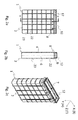
- Fig. 1a shows a sleeve 1 with a sleeve body 2.
- the sleeve height H extends and in the X direction extends the sleeve width B.
- connecting means 13 are provided in the form of slots.
- the sleeve body 2 also has in the horizontal direction extending stiffening elements 23 which are aligned parallel to each other. Furthermore, the sleeve body 2 stiffening elements 22 which extend in the vertical direction.
- the orientation of the stiffening elements 22 and 23 can be selected arbitrarily such that the angle which results between a stiffening element 23 oriented in the horizontal direction and a vertically oriented stiffening element 22 can be set or specified as desired.
- the stiffening elements extend perpendicular to one another and particularly preferably in the vertical or horizontal direction.
- the elements designated by the reference numeral 26 are receiving areas, by means of which a further device 14 (not shown) can be coupled to the sleeve body 2.
- the further device 14 is in this case at least partially enclosed by the receiving area 26.
- the further device 14 is, for example, cohesively, frictionally or positively locked in the receiving area 26 can be fixed.
- a plurality of receiving areas 26 are provided for receiving one or more further devices 14.
- Fig. 1b shows a sectional view of the in Fig. 1a A marked (ie running along the line A - A) interface.
- the Indian Fig. 1b shown sleeve body 2 extends on the one hand also in the height direction H and on the other hand in the direction of the sleeve depth T, which extends in the Z direction.
- an opening 7 is provided in the upper region 8 of the sleeve body 2.
- the wall element 4 can have long holes 13 in the upper region 8, also in the sections oriented in the sleeve depth direction. This also means that all in Fig.
- the stiffening elements 23 enclose the sleeve body 2 and thus the cavity 6 at least in sections in the circumferential direction.
- Fig. 1c shows a segment or a cross section of the wall element 4.
- This section or cross section of the wall element 4 for example, at the in Fig. 1b Be provided with b point marked.
- the wall element 4 consists at this point at least of the two layers 9 and 11, which form an inner skin 21 and an outer skin 20.
- the ratio of the thickness of the outer skin 20 to the thickness of the inner skin 21 is between 1: 2 and 1: 8, preferably between 1: 3 and 1: 5 and is particularly preferably 1: 4.
- the outer skin 20 is about 2 - 8 mm thick and the inner skin 8 - 32 mm thick.
- the outer skin 20 in this case consists of a first material component 11, which is preferred Plastic is, and the inner skin 21 consists of a second material component 9, which is preferably a plastic with added foaming agent, such as thermal foam, is. From the multilayer arrangement (sandwich construction) results in an increased static strength of the sleeve.
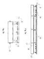
- a sleeve 1 with a sleeve body 2 is shown in the upper region 8 of the sleeve body 2.
- a further device 12 is arranged in this embodiment.
- the further device 12 has holes 17, by means of which screws and the slots 13 (not shown), a frictional connection can be generated.
- the stiffening elements 22 and the stiffening elements 23 are each formed uniformly and have no further receiving areas 26. This means that, in addition to an embodiment with two further devices 12 and 14, the sleeve 2 can also be designed only with a further device 12 or 14.
- Fig. 2b shows a sectional view of the in Fig. 2a A marked by A interface.
- Stiffening elements 22 and 23 As in the FIG. 2a are in the FIG. 2b Stiffening elements 22 and 23, a further device and the sleeve body 2 shown.
- FIG. 2c is a three-dimensional representation of the in Fig. 2a and 2b shown sleeve body 2 in conjunction with the further device 12 shown. From this, the opening 7 of the sleeve 1 can be seen, through which the lifting platform components to be arranged in the space 6 can be introduced into the sleeve 1 or into the sleeve body 2.
- FIG. 2d another device 12 is shown in plan view.
- the opening 7 of the further device 12 in this case has a substantially rectangular cross-section.
- the shape of the cross section of the further device 12 is substantially adaptable to the shape of the sleeve body 2 in the upper region 8. Such an adaptation can take place, for example, in the production phase.
- the sleeve body 2 is adapted in its upper region 8 to the shape of the further device 12 or is.
- the Fig. 2e shows a coupling device 16, as shown for example in Fig. 2b may be provided at the point indicated by b.
- a coupling device 16 couples the sleeve body 2 with the further device 12.
- the sleeve body 2 in this case has at least one slot 13 and the further device 12 has at least one hole 17.
- a bolt or screw member extending through the holes 13 and 17 therethrough, the sleeve body 2 and the further device 12 are positively or frictionally connected to each other. Due to the provided in the sleeve body 2 elongated hole 13 is a height adjustment or height adjustment of the entire sleeve 1 is possible.
- the further device 12 is in this case displaceable relative to the sleeve body 2 in the height direction H and by means of the connecting elements 15, preferably screw elements 15, fixable.
- an adjustment range of +/- 100 mm, preferably +/- 50 mm and more preferably of +/- 15 mm is provided.
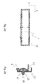
- Fig. 3a shows a side view of the further device 12.
- the further device 12 in its coupling region 27 to remove a plurality of holes 17 through which screws 15 extend.
- a plurality of further fastening elements 19 is provided, which may be provided for a coupling of the further device 12 with further components (not shown). It is also conceivable that components of the further device 12 are connected to one another by means of the fastening elements 19.
- FIG. 3b is a front view of the in Fig. 3a shown further device 12 shown.
- connection elements 15 are shown by way of example from this illustration.
- the Fig. 3c shows a plan view of the further device 12.
- the receiving or connecting devices 29 and 30 are used for attaching further components not shown and / or for stabilizing the further device 12.
- the receiving or connecting means 29 and 30 preferably have holes whose hole axis substantially in X or Z Direction is oriented.
- the further device 12 is further adjustable such that the plane formed by the upper surface of the further device 12, not only in height but also in their inclination can be adjusted continuously or in stages in any direction to the installation conditions. For this purpose, for example, the entire further device can be moved about the axis marked "A" or about an axis guided at the point "b".
- This means that the frame is designed to compensate for height and angle deviations generally multiaxial, the arrangement the pivot axes can be made at any point. However, it is also conceivable that the frame is pivotable about only one axis.
- Fig. 3d shows a sectional view through which in Fig. 3c with A marked interfaces.
- the receiving or connecting device 30 is in this case arranged substantially in the middle of the further device 12.
- Fig. 3e shows a sectional view through which in the Fig. 3c shown further device 12, at the interface marked b. From this representation, the receiving or connecting means 29 and 30 can be seen in a side view.
- the receiving or connecting device 30 is oriented towards the center 32 of the further device 12 and is therefore located within the space bounded by the main body 34.
- the receiving or connecting devices 29 are located on the outside of the main body 34 of the further device 12.
- the receiving or connecting devices 29 are at least partially surrounded by three sections of the main body 34.
- the receiving or connecting devices 30 are arranged substantially in the width direction B in the middle of the second device 12. However, it is also conceivable that several of these receiving or connecting means 30 are provided, which are arranged outside the center position.
- Fig. 3f shows a sectional view through which in the Fig. 3c shown further device 12, at the marked by C interface.
- the receiving and connecting devices 29 are surrounded by at least three sections of the main body 34.
- the receiving or connecting devices 29 are preferably provided repeatedly in the width direction B of the further device 12 or in the X direction.
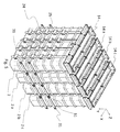
- a three-dimensional representation of a sleeve 1 is shown, on which a further device 14 is arranged.
- This further device 14 consists of a first element 24 and a second element 25. At least one of these elements 24, 25 is guided or fixed in at least one receiving region 26. Furthermore, one or each of the two elements 24, 25 can be made variable in its length.
- Fig. 4 further shows that the stiffening elements 23 may be made partially interrupted. An interruption of the stiffening elements 23 can be effected for example by further stiffening elements 22 or by recesses 36.
- the further device 14 enables, via the two elements 24 and 25, support or alignment of the entire device 1, 2 relative to the environment and causes an additional stiffening of the sleeve 1 and the sleeve body 2.
- the elements 24, 25 can be coupled to each other without a penetration of the sleeve body must be done. In the coupled state, the elements 24, 25 form the device 14 and thus a closed force frame.
- the elements 24, 24 are preferably made of steel and are designed so that they find anchorage in the ground and record by absorbing tensile forces the static load on the cassette wall (tie rod).
- Reference numeral 18 refers to the lower portion of the sleeve body 2 extending below the upper portion 8. The number and position or orientation of the wide device 14 or other devices 14 is arbitrarily executable.
- the sleeve body (2) has due to the multi-layered construction (sandwich construction) and variable complementary static by externally insertable power frame elements made of steel increased static strength.
- Fig. 5 a composite arrangement of any number of sleeves 1 is shown, which are connected by means of the other devices 14, which are arranged in the form of individual closed power frame around the individual sleeves 1 around.
- a force frame here is a mechanical device which is formed by elements 24, 25 and is designed to absorb external forces.
- the connection of two devices 14 takes place, for example, frictionally engaged, positive or field-locking.
- the devices 14 to 14c are screwed together, in addition to other connection variants also provide plug-in connections for a fixation or connection of the individual sleeves 1 in a composite arrangement.
- the holes identified by the reference numeral 31 in the second elements 25, the other devices 14 are connected to each other, preferably, each element 25 has two holes 31.
- the holes 31 can also be designed as slots or straight flank, where by means of a screw of another device 14 of a further sleeve 1 by clamping a connection is generated.
- the sleeves 1a to 1d are connectable not only in the Z direction to composite arrangements, but also in the X direction, ie composite arrangements can be created in the Z direction and / or X direction.
- An advantage of these composite arrangements is, for example, that the sleeves 1 form a stable unit for transport and / or during transport.
Landscapes
- Engineering & Computer Science (AREA)
- Architecture (AREA)
- Mechanical Engineering (AREA)
- Structural Engineering (AREA)
- Civil Engineering (AREA)
- Life Sciences & Earth Sciences (AREA)
- Geology (AREA)
- Forms Removed On Construction Sites Or Auxiliary Members Thereof (AREA)
- Bridges Or Land Bridges (AREA)
- Auxiliary Methods And Devices For Loading And Unloading (AREA)
- Refuge Islands, Traffic Blockers, Or Guard Fence (AREA)
Applications Claiming Priority (1)
| Application Number | Priority Date | Filing Date | Title |
|---|---|---|---|
| DE200910019143 DE102009019143A1 (de) | 2009-04-29 | 2009-04-29 | Hebebühne mit anpassbarer Aufnahmehülse |
Publications (3)
| Publication Number | Publication Date |
|---|---|
| EP2246502A2 true EP2246502A2 (fr) | 2010-11-03 |
| EP2246502A3 EP2246502A3 (fr) | 2011-01-19 |
| EP2246502B1 EP2246502B1 (fr) | 2012-12-05 |
Family
ID=42357766
Family Applications (1)
| Application Number | Title | Priority Date | Filing Date |
|---|---|---|---|
| EP20100159711 Not-in-force EP2246502B1 (fr) | 2009-04-29 | 2010-04-13 | Elévateur doté d'une douille de réception adaptable |
Country Status (3)
| Country | Link |
|---|---|
| EP (1) | EP2246502B1 (fr) |
| DE (1) | DE102009019143A1 (fr) |
| DK (1) | DK2246502T3 (fr) |
Cited By (2)
| Publication number | Priority date | Publication date | Assignee | Title |
|---|---|---|---|---|
| FR3007399A1 (fr) * | 2013-06-21 | 2014-12-26 | Renpat | Installation d'un dispositif elevateur de personnes adosse a un escalier droit dans un caisson aux dimensions determinees |
| EP4635897A1 (fr) * | 2024-04-15 | 2025-10-22 | AUTOPSTENHOJ GmbH | Plate-forme de levage de sous-sol pour lever des véhicules et procédé de production d'une plate-forme de levage de sous-sol pour lever des véhicules |
Families Citing this family (2)
| Publication number | Priority date | Publication date | Assignee | Title |
|---|---|---|---|---|
| DE102011016926A1 (de) * | 2011-04-13 | 2012-10-18 | Hans Balzer | Verfahren zur Herstellung einer im Boden versenkt angeordneten Hebeeinrichtung, und Verwendung einer solchen |
| DE102011101159B4 (de) * | 2011-05-11 | 2013-09-05 | Roland Hörnstein GmbH & Co. KG | Einbaukassette für Unterflurhebebühnen |
Family Cites Families (8)
| Publication number | Priority date | Publication date | Assignee | Title |
|---|---|---|---|---|
| DE4324339C2 (de) * | 1993-05-26 | 1996-03-28 | Balzer Heide | Montage- und Reparaturgrube sowie Verfahren zur Herstellung derselben |
| DE20013746U1 (de) * | 2000-08-10 | 2000-12-28 | Herrmann, Johannes, 93413 Cham | Einbaukassette für eine Unterflur-Hebebühne für Kraftfahrzeuge sowie eine in eine solche Einbaukassette eingebaute Hebebühne |
| DE20114804U1 (de) * | 2001-09-07 | 2002-02-14 | Herrmann, Johannes, 93413 Cham | Kraftfahrzeug-Unterflurhebebühne |
| US20040149520A1 (en) * | 2002-09-20 | 2004-08-05 | Bryan Taylor | Inground lift |
| US20050079040A1 (en) * | 2003-10-09 | 2005-04-14 | Roger Perlstein | Lift system, lift retrofit system and method for installation of same |
| DE102005005498B3 (de) * | 2005-02-04 | 2006-05-24 | Roland Hörnstein GmbH & Co. KG | Einbaukassette für Unterflurhebebühnen mit einer sackähnlichen Schutzhülle |
| DE102005031934A1 (de) * | 2005-07-08 | 2007-01-11 | Roland Hörnstein GmbH & Co. KG | Einbaukassette für Unterflurhebebühnen mit innerer Schutzhülle |
| DE102005032762A1 (de) * | 2005-07-14 | 2007-01-25 | Roland Hörnstein GmbH & Co. KG | Einbaukassette für Unterflurhebebühnen mit einer äusseren Schutzhülle |
-
2009
- 2009-04-29 DE DE200910019143 patent/DE102009019143A1/de not_active Withdrawn
-
2010
- 2010-04-13 DK DK10159711.0T patent/DK2246502T3/da active
- 2010-04-13 EP EP20100159711 patent/EP2246502B1/fr not_active Not-in-force
Non-Patent Citations (1)
| Title |
|---|
| None |
Cited By (2)
| Publication number | Priority date | Publication date | Assignee | Title |
|---|---|---|---|---|
| FR3007399A1 (fr) * | 2013-06-21 | 2014-12-26 | Renpat | Installation d'un dispositif elevateur de personnes adosse a un escalier droit dans un caisson aux dimensions determinees |
| EP4635897A1 (fr) * | 2024-04-15 | 2025-10-22 | AUTOPSTENHOJ GmbH | Plate-forme de levage de sous-sol pour lever des véhicules et procédé de production d'une plate-forme de levage de sous-sol pour lever des véhicules |
Also Published As
| Publication number | Publication date |
|---|---|
| DK2246502T3 (da) | 2013-03-18 |
| DE102009019143A1 (de) | 2010-11-11 |
| EP2246502A3 (fr) | 2011-01-19 |
| EP2246502B1 (fr) | 2012-12-05 |
Similar Documents
| Publication | Publication Date | Title |
|---|---|---|
| EP3298201B1 (fr) | Système de protection d'une tranchée | |
| EP3752692B1 (fr) | Système grimpant et procédé pour faire fonctionner un système grimpant | |
| EP1983111A1 (fr) | Coffrage destiné à limiter les sections de parois moulées, élément de coffrage et procédé de fabrication d'une paroi moulée dans le sol | |
| EP2246502B1 (fr) | Elévateur doté d'une douille de réception adaptable | |
| DE3615601C1 (de) | Rohrtragbohle fuer eine kombinierte Spundwand | |
| DE102011010042A1 (de) | Dreibaum zum Versetzen schwerer Lasten | |
| EP2025816A1 (fr) | Procédé de fabrication d'un élément de muret et élément de muret fabriqué après le procédé pour un muret de séparation du trafic | |
| EP4421240B1 (fr) | Barrière pouvant être utilisée comme barrière contre act de terrorisme | |
| DE3443451C1 (de) | Vorrichtung zum Einrichten einer Stütze | |
| DE4324339C2 (de) | Montage- und Reparaturgrube sowie Verfahren zur Herstellung derselben | |
| EP3848512B1 (fr) | Procédé de création d'un élément de fondation dans le sol et élément de fondation | |
| DE102004010927B4 (de) | Verfahren und Vorrichtung zum Erstellen von insbesondere viertel-, halb- oder vollgewendelten Ortbeton-Treppen | |
| DE4345415C2 (de) | Montagegrube mit doppelwandiger Stahlkassette | |
| DE102016120047B4 (de) | Vorrichtung und Verfahren zur einstückigen Herstellung eines drei Seitenelemente sowie ein Bodenelement und/oder ein Deckenelement aufweisenden Raummoduls | |
| EP3228757B1 (fr) | Dispositif d'armature | |
| DE2645071A1 (de) | Verfahrbare ramme | |
| DE3823784A1 (de) | Verfahren, abdichtungselemente und vorrichtung zur herstellung einer abdichtungsschlitzwand | |
| EP3029206B1 (fr) | Dispositif de fermeture de puits en plusieurs parties | |
| DE102024107581B4 (de) | Vorrichtung und Verfahren zur Tiefengründung von Fundamenten für Lärm- und Sichtschutzbauten | |
| EP2511223B1 (fr) | Procédé de fabrication d'un dispositif de levage agencé au ras du sol, et utilisation de celui-ci | |
| DE2942428A1 (de) | Verfahren zum ausbau von hafenanlagen o.dgl. | |
| EP3762314B1 (fr) | Conteneur métallique praticable à pied, procédé de fabrication d'un conteneur métallique praticable à pied, bâtiment | |
| DE2256658A1 (de) | Vorrichtung zum heben und senken von vorgefertigten, kastenfoermigen werkstuecken mit geschlossenem boden | |
| DE69308114T2 (de) | Verfahren zur Herstellung von Querdurchgängen unter Eisenbahntrassen | |
| EP2642031B1 (fr) | Procédé de fabrication d'un équipement de protection pour la protection contre les vibrations dans le sol ainsi que dispositif correspondant |
Legal Events
| Date | Code | Title | Description |
|---|---|---|---|
| PUAI | Public reference made under article 153(3) epc to a published international application that has entered the european phase |
Free format text: ORIGINAL CODE: 0009012 |
|
| AK | Designated contracting states |
Kind code of ref document: A2 Designated state(s): AT BE BG CH CY CZ DE DK EE ES FI FR GB GR HR HU IE IS IT LI LT LU LV MC MK MT NL NO PL PT RO SE SI SK SM TR |
|
| AX | Request for extension of the european patent |
Extension state: AL BA ME RS |
|
| PUAL | Search report despatched |
Free format text: ORIGINAL CODE: 0009013 |
|
| AK | Designated contracting states |
Kind code of ref document: A3 Designated state(s): AT BE BG CH CY CZ DE DK EE ES FI FR GB GR HR HU IE IS IT LI LT LU LV MC MK MT NL NO PL PT RO SE SI SK SM TR |
|
| AX | Request for extension of the european patent |
Extension state: AL BA ME RS |
|
| 17P | Request for examination filed |
Effective date: 20110719 |
|
| GRAP | Despatch of communication of intention to grant a patent |
Free format text: ORIGINAL CODE: EPIDOSNIGR1 |
|
| GRAS | Grant fee paid |
Free format text: ORIGINAL CODE: EPIDOSNIGR3 |
|
| GRAA | (expected) grant |
Free format text: ORIGINAL CODE: 0009210 |
|
| AK | Designated contracting states |
Kind code of ref document: B1 Designated state(s): AT BE BG CH CY CZ DE DK EE ES FI FR GB GR HR HU IE IS IT LI LT LU LV MC MK MT NL NO PL PT RO SE SI SK SM TR |
|
| REG | Reference to a national code |
Ref country code: GB Ref legal event code: FG4D Free format text: NOT ENGLISH |
|
| REG | Reference to a national code |
Ref country code: CH Ref legal event code: EP |
|
| REG | Reference to a national code |
Ref country code: AT Ref legal event code: REF Ref document number: 587386 Country of ref document: AT Kind code of ref document: T Effective date: 20121215 |
|
| REG | Reference to a national code |
Ref country code: IE Ref legal event code: FG4D Free format text: LANGUAGE OF EP DOCUMENT: GERMAN |
|
| REG | Reference to a national code |
Ref country code: DE Ref legal event code: R096 Ref document number: 502010001790 Country of ref document: DE Effective date: 20130124 |
|
| REG | Reference to a national code |
Ref country code: DK Ref legal event code: T3 |
|
| PG25 | Lapsed in a contracting state [announced via postgrant information from national office to epo] |
Ref country code: LT Free format text: LAPSE BECAUSE OF FAILURE TO SUBMIT A TRANSLATION OF THE DESCRIPTION OR TO PAY THE FEE WITHIN THE PRESCRIBED TIME-LIMIT Effective date: 20121205 Ref country code: ES Free format text: LAPSE BECAUSE OF FAILURE TO SUBMIT A TRANSLATION OF THE DESCRIPTION OR TO PAY THE FEE WITHIN THE PRESCRIBED TIME-LIMIT Effective date: 20130316 Ref country code: SE Free format text: LAPSE BECAUSE OF FAILURE TO SUBMIT A TRANSLATION OF THE DESCRIPTION OR TO PAY THE FEE WITHIN THE PRESCRIBED TIME-LIMIT Effective date: 20121205 Ref country code: FI Free format text: LAPSE BECAUSE OF FAILURE TO SUBMIT A TRANSLATION OF THE DESCRIPTION OR TO PAY THE FEE WITHIN THE PRESCRIBED TIME-LIMIT Effective date: 20121205 Ref country code: NO Free format text: LAPSE BECAUSE OF FAILURE TO SUBMIT A TRANSLATION OF THE DESCRIPTION OR TO PAY THE FEE WITHIN THE PRESCRIBED TIME-LIMIT Effective date: 20130305 |
|
| REG | Reference to a national code |
Ref country code: NL Ref legal event code: VDEP Effective date: 20121205 |
|
| REG | Reference to a national code |
Ref country code: LT Ref legal event code: MG4D |
|
| PG25 | Lapsed in a contracting state [announced via postgrant information from national office to epo] |
Ref country code: PL Free format text: LAPSE BECAUSE OF FAILURE TO SUBMIT A TRANSLATION OF THE DESCRIPTION OR TO PAY THE FEE WITHIN THE PRESCRIBED TIME-LIMIT Effective date: 20121205 Ref country code: GR Free format text: LAPSE BECAUSE OF FAILURE TO SUBMIT A TRANSLATION OF THE DESCRIPTION OR TO PAY THE FEE WITHIN THE PRESCRIBED TIME-LIMIT Effective date: 20130306 Ref country code: SI Free format text: LAPSE BECAUSE OF FAILURE TO SUBMIT A TRANSLATION OF THE DESCRIPTION OR TO PAY THE FEE WITHIN THE PRESCRIBED TIME-LIMIT Effective date: 20121205 Ref country code: LV Free format text: LAPSE BECAUSE OF FAILURE TO SUBMIT A TRANSLATION OF THE DESCRIPTION OR TO PAY THE FEE WITHIN THE PRESCRIBED TIME-LIMIT Effective date: 20121205 |
|
| PG25 | Lapsed in a contracting state [announced via postgrant information from national office to epo] |
Ref country code: CZ Free format text: LAPSE BECAUSE OF FAILURE TO SUBMIT A TRANSLATION OF THE DESCRIPTION OR TO PAY THE FEE WITHIN THE PRESCRIBED TIME-LIMIT Effective date: 20121205 Ref country code: SK Free format text: LAPSE BECAUSE OF FAILURE TO SUBMIT A TRANSLATION OF THE DESCRIPTION OR TO PAY THE FEE WITHIN THE PRESCRIBED TIME-LIMIT Effective date: 20121205 Ref country code: EE Free format text: LAPSE BECAUSE OF FAILURE TO SUBMIT A TRANSLATION OF THE DESCRIPTION OR TO PAY THE FEE WITHIN THE PRESCRIBED TIME-LIMIT Effective date: 20121205 Ref country code: BG Free format text: LAPSE BECAUSE OF FAILURE TO SUBMIT A TRANSLATION OF THE DESCRIPTION OR TO PAY THE FEE WITHIN THE PRESCRIBED TIME-LIMIT Effective date: 20130305 Ref country code: IS Free format text: LAPSE BECAUSE OF FAILURE TO SUBMIT A TRANSLATION OF THE DESCRIPTION OR TO PAY THE FEE WITHIN THE PRESCRIBED TIME-LIMIT Effective date: 20130405 |
|
| PG25 | Lapsed in a contracting state [announced via postgrant information from national office to epo] |
Ref country code: NL Free format text: LAPSE BECAUSE OF FAILURE TO SUBMIT A TRANSLATION OF THE DESCRIPTION OR TO PAY THE FEE WITHIN THE PRESCRIBED TIME-LIMIT Effective date: 20121205 Ref country code: PT Free format text: LAPSE BECAUSE OF FAILURE TO SUBMIT A TRANSLATION OF THE DESCRIPTION OR TO PAY THE FEE WITHIN THE PRESCRIBED TIME-LIMIT Effective date: 20130405 Ref country code: RO Free format text: LAPSE BECAUSE OF FAILURE TO SUBMIT A TRANSLATION OF THE DESCRIPTION OR TO PAY THE FEE WITHIN THE PRESCRIBED TIME-LIMIT Effective date: 20121205 |
|
| PLBE | No opposition filed within time limit |
Free format text: ORIGINAL CODE: 0009261 |
|
| STAA | Information on the status of an ep patent application or granted ep patent |
Free format text: STATUS: NO OPPOSITION FILED WITHIN TIME LIMIT |
|
| BERE | Be: lapsed |
Owner name: HERRMANN A.G. Effective date: 20130430 |
|
| 26N | No opposition filed |
Effective date: 20130906 |
|
| PG25 | Lapsed in a contracting state [announced via postgrant information from national office to epo] |
Ref country code: CY Free format text: LAPSE BECAUSE OF FAILURE TO SUBMIT A TRANSLATION OF THE DESCRIPTION OR TO PAY THE FEE WITHIN THE PRESCRIBED TIME-LIMIT Effective date: 20121205 Ref country code: HR Free format text: LAPSE BECAUSE OF FAILURE TO SUBMIT A TRANSLATION OF THE DESCRIPTION OR TO PAY THE FEE WITHIN THE PRESCRIBED TIME-LIMIT Effective date: 20121205 Ref country code: MC Free format text: LAPSE BECAUSE OF FAILURE TO SUBMIT A TRANSLATION OF THE DESCRIPTION OR TO PAY THE FEE WITHIN THE PRESCRIBED TIME-LIMIT Effective date: 20121205 |
|
| REG | Reference to a national code |
Ref country code: DE Ref legal event code: R097 Ref document number: 502010001790 Country of ref document: DE Effective date: 20130906 |
|
| REG | Reference to a national code |
Ref country code: IE Ref legal event code: MM4A |
|
| PG25 | Lapsed in a contracting state [announced via postgrant information from national office to epo] |
Ref country code: BE Free format text: LAPSE BECAUSE OF NON-PAYMENT OF DUE FEES Effective date: 20130430 |
|
| REG | Reference to a national code |
Ref country code: FR Ref legal event code: ST Effective date: 20131231 |
|
| PG25 | Lapsed in a contracting state [announced via postgrant information from national office to epo] |
Ref country code: FR Free format text: LAPSE BECAUSE OF NON-PAYMENT OF DUE FEES Effective date: 20130430 |
|
| PG25 | Lapsed in a contracting state [announced via postgrant information from national office to epo] |
Ref country code: IE Free format text: LAPSE BECAUSE OF NON-PAYMENT OF DUE FEES Effective date: 20130413 |
|
| PGFP | Annual fee paid to national office [announced via postgrant information from national office to epo] |
Ref country code: DE Payment date: 20140624 Year of fee payment: 5 Ref country code: IT Payment date: 20140424 Year of fee payment: 5 |
|
| PGFP | Annual fee paid to national office [announced via postgrant information from national office to epo] |
Ref country code: DK Payment date: 20140424 Year of fee payment: 5 |
|
| REG | Reference to a national code |
Ref country code: CH Ref legal event code: PL |
|
| GBPC | Gb: european patent ceased through non-payment of renewal fee |
Effective date: 20140413 |
|
| PG25 | Lapsed in a contracting state [announced via postgrant information from national office to epo] |
Ref country code: CH Free format text: LAPSE BECAUSE OF NON-PAYMENT OF DUE FEES Effective date: 20140430 Ref country code: LI Free format text: LAPSE BECAUSE OF NON-PAYMENT OF DUE FEES Effective date: 20140430 Ref country code: GB Free format text: LAPSE BECAUSE OF NON-PAYMENT OF DUE FEES Effective date: 20140413 |
|
| PG25 | Lapsed in a contracting state [announced via postgrant information from national office to epo] |
Ref country code: MT Free format text: LAPSE BECAUSE OF FAILURE TO SUBMIT A TRANSLATION OF THE DESCRIPTION OR TO PAY THE FEE WITHIN THE PRESCRIBED TIME-LIMIT Effective date: 20121205 |
|
| PG25 | Lapsed in a contracting state [announced via postgrant information from national office to epo] |
Ref country code: SM Free format text: LAPSE BECAUSE OF FAILURE TO SUBMIT A TRANSLATION OF THE DESCRIPTION OR TO PAY THE FEE WITHIN THE PRESCRIBED TIME-LIMIT Effective date: 20121205 |
|
| PG25 | Lapsed in a contracting state [announced via postgrant information from national office to epo] |
Ref country code: TR Free format text: LAPSE BECAUSE OF FAILURE TO SUBMIT A TRANSLATION OF THE DESCRIPTION OR TO PAY THE FEE WITHIN THE PRESCRIBED TIME-LIMIT Effective date: 20121205 |
|
| PG25 | Lapsed in a contracting state [announced via postgrant information from national office to epo] |
Ref country code: MK Free format text: LAPSE BECAUSE OF FAILURE TO SUBMIT A TRANSLATION OF THE DESCRIPTION OR TO PAY THE FEE WITHIN THE PRESCRIBED TIME-LIMIT Effective date: 20121205 Ref country code: LU Free format text: LAPSE BECAUSE OF NON-PAYMENT OF DUE FEES Effective date: 20130413 Ref country code: HU Free format text: LAPSE BECAUSE OF FAILURE TO SUBMIT A TRANSLATION OF THE DESCRIPTION OR TO PAY THE FEE WITHIN THE PRESCRIBED TIME-LIMIT; INVALID AB INITIO Effective date: 20100413 |
|
| REG | Reference to a national code |
Ref country code: DE Ref legal event code: R119 Ref document number: 502010001790 Country of ref document: DE |
|
| REG | Reference to a national code |
Ref country code: DK Ref legal event code: EBP Effective date: 20150430 |
|
| PG25 | Lapsed in a contracting state [announced via postgrant information from national office to epo] |
Ref country code: IT Free format text: LAPSE BECAUSE OF NON-PAYMENT OF DUE FEES Effective date: 20150413 Ref country code: DE Free format text: LAPSE BECAUSE OF NON-PAYMENT OF DUE FEES Effective date: 20151103 |
|
| PG25 | Lapsed in a contracting state [announced via postgrant information from national office to epo] |
Ref country code: DK Free format text: LAPSE BECAUSE OF NON-PAYMENT OF DUE FEES Effective date: 20150430 |
|
| REG | Reference to a national code |
Ref country code: AT Ref legal event code: MM01 Ref document number: 587386 Country of ref document: AT Kind code of ref document: T Effective date: 20150413 |
|
| PG25 | Lapsed in a contracting state [announced via postgrant information from national office to epo] |
Ref country code: AT Free format text: LAPSE BECAUSE OF NON-PAYMENT OF DUE FEES Effective date: 20150413 |