EP2246503A2 - Echafaudage suspendu à une toiture - Google Patents
Echafaudage suspendu à une toiture Download PDFInfo
- Publication number
- EP2246503A2 EP2246503A2 EP10001547A EP10001547A EP2246503A2 EP 2246503 A2 EP2246503 A2 EP 2246503A2 EP 10001547 A EP10001547 A EP 10001547A EP 10001547 A EP10001547 A EP 10001547A EP 2246503 A2 EP2246503 A2 EP 2246503A2
- Authority
- EP
- European Patent Office
- Prior art keywords
- support
- strut
- roof
- framework according
- leg
- Prior art date
- Legal status (The legal status is an assumption and is not a legal conclusion. Google has not performed a legal analysis and makes no representation as to the accuracy of the status listed.)
- Withdrawn
Links
- 239000000725 suspension Substances 0.000 claims description 37
- 238000006073 displacement reaction Methods 0.000 claims 1
- 230000000284 resting effect Effects 0.000 claims 1
- XEEYBQQBJWHFJM-UHFFFAOYSA-N Iron Chemical compound [Fe] XEEYBQQBJWHFJM-UHFFFAOYSA-N 0.000 description 10
- 229910052782 aluminium Inorganic materials 0.000 description 7
- XAGFODPZIPBFFR-UHFFFAOYSA-N aluminium Chemical compound [Al] XAGFODPZIPBFFR-UHFFFAOYSA-N 0.000 description 7
- 229910052742 iron Inorganic materials 0.000 description 5
- 239000000463 material Substances 0.000 description 5
- 238000003780 insertion Methods 0.000 description 3
- 230000037431 insertion Effects 0.000 description 3
- 239000003351 stiffener Substances 0.000 description 3
- 229910000831 Steel Inorganic materials 0.000 description 2
- 239000000969 carrier Substances 0.000 description 2
- 238000009415 formwork Methods 0.000 description 2
- 235000000396 iron Nutrition 0.000 description 2
- 125000006850 spacer group Chemical group 0.000 description 2
- 239000010959 steel Substances 0.000 description 2
- 241000238631 Hexapoda Species 0.000 description 1
- 241000282346 Meles meles Species 0.000 description 1
- 238000009434 installation Methods 0.000 description 1
- 229910052751 metal Inorganic materials 0.000 description 1
- 239000002184 metal Substances 0.000 description 1
- 238000000034 method Methods 0.000 description 1
- 230000002787 reinforcement Effects 0.000 description 1
- 238000003466 welding Methods 0.000 description 1
- 239000002023 wood Substances 0.000 description 1
Images


Classifications
-
- E—FIXED CONSTRUCTIONS
- E04—BUILDING
- E04G—SCAFFOLDING; FORMS; SHUTTERING; BUILDING IMPLEMENTS OR AIDS, OR THEIR USE; HANDLING BUILDING MATERIALS ON THE SITE; REPAIRING, BREAKING-UP OR OTHER WORK ON EXISTING BUILDINGS
- E04G3/00—Scaffolds essentially supported by building constructions, e.g. adjustable in height
- E04G3/22—Scaffolds essentially supported by building constructions, e.g. adjustable in height supported by roofs or ceilings
-
- E—FIXED CONSTRUCTIONS
- E04—BUILDING
- E04G—SCAFFOLDING; FORMS; SHUTTERING; BUILDING IMPLEMENTS OR AIDS, OR THEIR USE; HANDLING BUILDING MATERIALS ON THE SITE; REPAIRING, BREAKING-UP OR OTHER WORK ON EXISTING BUILDINGS
- E04G21/00—Preparing, conveying, or working-up building materials or building elements in situ; Other devices or measures for constructional work
- E04G21/32—Safety or protective measures for persons during the construction of buildings
- E04G21/3204—Safety or protective measures for persons during the construction of buildings against falling down
- E04G21/3214—Means for working on roofs
-
- E—FIXED CONSTRUCTIONS
- E04—BUILDING
- E04G—SCAFFOLDING; FORMS; SHUTTERING; BUILDING IMPLEMENTS OR AIDS, OR THEIR USE; HANDLING BUILDING MATERIALS ON THE SITE; REPAIRING, BREAKING-UP OR OTHER WORK ON EXISTING BUILDINGS
- E04G3/00—Scaffolds essentially supported by building constructions, e.g. adjustable in height
- E04G3/24—Scaffolds essentially supported by building constructions, e.g. adjustable in height specially adapted for particular parts of buildings or for buildings of particular shape, e.g. chimney stacks or pylons
- E04G3/26—Scaffolds essentially supported by building constructions, e.g. adjustable in height specially adapted for particular parts of buildings or for buildings of particular shape, e.g. chimney stacks or pylons specially adapted for working on roofs
- E04G3/265—Scaffolds essentially supported by building constructions, e.g. adjustable in height specially adapted for particular parts of buildings or for buildings of particular shape, e.g. chimney stacks or pylons specially adapted for working on roofs with means to adapt it to a variable pitch of the roof
-
- E—FIXED CONSTRUCTIONS
- E04—BUILDING
- E04G—SCAFFOLDING; FORMS; SHUTTERING; BUILDING IMPLEMENTS OR AIDS, OR THEIR USE; HANDLING BUILDING MATERIALS ON THE SITE; REPAIRING, BREAKING-UP OR OTHER WORK ON EXISTING BUILDINGS
- E04G5/00—Component parts or accessories for scaffolds
- E04G5/04—Means for fastening, supporting, or bracing scaffolds on or against building constructions
- E04G5/041—Means for fastening, supporting, or bracing scaffolds on or against building constructions for fastening scaffolds on roof frameworks or on roofs
Definitions
- the invention relates to a suspension framework according to the preamble of claim 1.
- a scaffolding designed for work on a roof is out EP 0 881 341 A1 known.
- the hanging strut projects above the eaves upwards.
- each retaining arms are fixed, which are pivotally attached to tabs on the top of the rafters.
- a support pin with mutually arranged transverse bores is fixed at the top of the rafters between the pivot axis of the support arm and the suspension strut through which a retaining pin is plugged, on which the support arm is supported.
- the object of the invention is to provide a suspension framework with which all assembly work on a roof can be performed and which allows an accurate horizontal positioning of the tread under full load on the tread.
- each carrier is provided with a hanging strut, which is articulated below the upper edge of the roof rafter about a horizontal axis pivotable.
- the hanging strut is connected to a support that attaches to the rafter from below supported, and that at a distance from the pivot axis of the suspension strut on the side remote from the tread side of the pivot axis.
- the support for adjusting the horizontal position of the tread is adjustable in length.
- the support consists of an outer tube and a telescopically guided inner tube inside.
- a nut is fixed in the inner tube, in which the length adjustability of the support a threaded spindle is screwed, which is mounted axially immovably in the outer tube, wherein the threaded spindle for actuating with its lower end protrudes from the outer tube.
- both the pivot axis of the suspension strut and the length-adjustable support are arranged below the upper edge of the roof rafter, all work on the roof can be carried out from the beginning to the end with the suspension framework according to the invention, for example the attachment of the formwork, the roof skin, such as the roof tile. the gutter, the snow guard grille, the insect screen in the eaves area, etc ..
- the suspension framework according to the invention is infinitely horizontally adjustable under full load of the tread, as before and during the entire adjustment process is a positive connection of outer tube and inner tube.
- Both the support and the suspension strut which is pivotably connected to the rafter, preferably extend obliquely from the tread upwards from below.
- the carrier does not need to be attached to each roof rafter of the roof. Rather, between two rafters, to each of which a carrier is attached, one or more rafters may be provided without a carrier.
- the hanging strut For pivotable mounting of the hanging strut, it preferably has at its upper end a bolt which rotatably engages in a bore in the rafter.
- the bolt is preferably designed as a hollow bolt with an internal thread.
- the bolt which runs horizontally and parallel to the eaves, can for example be attached to a flange or the like hanging strut on one side of the roof rafter.
- the other end of the hollow bolt which does not protrude from the rafter, may be provided with an internal thread into which a threaded bolt with external thread, optionally screwed with attached washer and a transverse actuating lever on the side facing away from the thread for fixing the carrier.
- the support is preferably attached to the side facing away from the tread side of the suspension strut on an extension of the support strut. While the support is attached to the end remote from the tread end of the extension of the support strut, the suspension strut is attached to the supporting strut adjacent end of the extension.
- the suspended scaffold can be adapted to a roof pitch of preferably 0 to 45 degrees.
- the length adjustability of the support depends essentially on the length of the threaded spindle, the length of the outer tube and the length of the inner tube.
- the support preferably has a shoe for support on the underside of the roof rafter.
- the shoe may be formed by a crosspiece fitting on the underside of the roof rafter and two flanges or the like arranged on both sides of the roof rafter.
- the outer tube of the support can be connected by the extension of the support strut with the hanging strut.
- the hanging strut and the extension of the support strut may be provided for example as a plate, sheet metal or the like stiffening.
- the support struts including their extension for attachment of the support strut are preferably made of a tube made of aluminum material.
- the vertical struts and the suspension strut are preferably formed as a tube of aluminum material.
- the suspension strut and the support strut can be welded together, as well as the vertical strut and the support strut.
- the stiffener may be made of aluminum material and welded to the hanger strut and / or the extension of the support strut.
- the outer and inner tube of the telescopic support is preferably made of steel. So that the outer tube can be connected to the support strut or its extension, a screw connection is preferably provided. This can be done on the Outer tube of the support may be provided a flange which is bolted to the stiffener, which is fixed for example by welding to the suspension strut and the extension of the support strut. The screw connection is then made by bolts, the holes in the flange and aligned holes in the stiffening protrude.
- a vertical strut may be attached at the end facing away from the roof of the support strut.
- at least one preferably length-adjustable, for example, telescoping longitudinal spar can be provided to secure the tread on the side facing away from the roof and / or the roof facing side.
- the longitudinal beams can be releasably secured to the vertical struts or or hanging struts. Due to the length adjustability of the longitudinal beams, the framework can be adapted to different distances of the rafters.
- fastening means for fastening a safety net stretched between the vertical struts and underneath the support struts can be provided on the vertical struts and the support struts.
- the tread preferably consists of plates which rest on the support struts of adjacent carriers.
- the panels which have a bearing capacity for at least one person carrying out the roof work, can be designed in any desired manner, for example as a grate or the like. Preferably, however, they are formed by wooden planks.
- At least one mounting rail has on each side of the running surface at least one projection which engages in a recess in a bearing on the side of the support strut facing the strut or in a vertical strut.
- a wedge slidably guided on a mounting rail can be provided, which engages on a stop fastened to the adjacent mounting rail, which can have a complementarily formed wedge surface.
- the angle-shaped mounting rails are preferably U-shaped, d. H. they have, in addition to the lower horizontal leg on an upper horizontal leg, so that the longitudinal edge of the tread engages in the opening of the U-profile.
- the upper horizontal leg is preferably formed shorter than the lower horizontal leg of the support rail to insert the tread from above can.
- the upper and lower horizontal legs of the U-shaped mounting rail can be provided to guide the locking wedge with longitudinal slots.
- a support rail z. B. on its lower horizontal leg of the profile have a projection which engages in a recess of the adjacent support rail.
- the projection for lateral and vertical fixing of adjacent mounting rails preferably engages in a recess on the lower leg of the adjacent mounting rail.
- recesses for connecting pieces can be provided at the ends of the plates, so bores or the like.
- the connectors have, for example, two downwardly projecting projections which are inserted into recesses at the ends of adjacent plates.
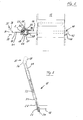
- FIG. 1 has the roof 1 on a building, not shown building rafters 2 on purlins 3, a formwork 4 with roof battens 5, on which roof tiles 6 are laid and a gutter 7 on the final lath 8 on the eaves 9 on.
- a carrier 11 On the rafters 2, a carrier 11 is fixed, which has a support strut 12 on which a tread 13 rests.
- the tread 13, which consists for example of planks, extends below the eaves 9 and along the same.
- Each carrier 11 has a suspension strut 14.
- the suspension strut 14 is hinged below the upper edge 15 of the roof rafter 2 about a horizontal, parallel to the eaves 9 axis extending pivotally.
- the carrier 11 is designed as a two-armed lever, wherein the one lever arm is formed by the support strut 12, while the second formed by an extension 18 of the support strut 12 lever arm is supported with a support 17 on the underside 16 of the roof rafter 2. While the support 17 is fastened to the end of the extension 18 facing away from the running surface 13, the suspension strut 14 is fastened to the end of the extension 18 adjacent to the support strut 12.
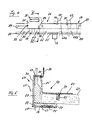
- the pivot axis of the suspension strut 14, which also represents the axis of rotation of the two-armed lever is according to FIG. 2 formed by a hollow bolt 19 which is fixed to a tab 21 at the upper end of the hanger strut 14, which is arranged laterally on the rafter 2 ( FIG. 1 ).
- the tab 21 is stiffened with a stiffening rib 22 which is attached to the tubular hanging strut 14.
- the hollow pin 19 projects into a bore 23 in the rafter 2.
- the hollow pin 19 has an internal thread into which a screw bolt 25 with washer 26 is screwed by means of a transverse actuating lever 27.
- the suspension strut 14 and the support 17 extend away from the tread 13 obliquely from bottom to top.
- the side facing away from the roof eaves 9 side of the roof 1 are inclined towards the top.
- the support 17 is adjustable in length, in order to align the tread 13 horizontally according to the roof pitch.
- FIG. 3 has the length-adjustable support 17, an outer tube 28 in which an inner tube 29 is arranged telescopically.
- the outer tube 28 and the inner tube 29 are formed as polygonal, for example square tube.
- a nut 31 is fixed, in the length adjustment of the support 17, a threaded spindle 32 is screwed, which is mounted axially immovably in a bearing 33 which is provided at the lower end of the outer tube 28.
- a polygon 34 is attached to the spindle 32, which is provided at the lower end of the support 17.
- the support 17 is supported with a shoe 35 on the underside 16 of the roof rafter 2 at a distance from the hanger strut 14 on the side remote from the running surface 13 side of the pivot axis (bolt 19) on the rafters 2 from.
- the shoe 35 is preferably formed by a fitting on the underside of the roof rafter 2 crosspiece 36 and two arranged on one side or the other side of the roof rafter flanges 37, 38 or the like portions. ( Figure 1 to 3 ).
- the outer tube 28 of the support 17 is connected to the suspension strut 14 and the extension 18 of the support strut 12. This is according to FIG. 1 a plate 39 is provided, which also serves as a stiffener.
- the support strut 12 including its extension 18 is preferably made of an aluminum tube, as well as the plate 39 is made of an aluminum material.
- the extension 18, the plate 39 and the suspension strut 14 can be welded together.
- the outer tube 28 of the support 17 is preferably made of steel.
- the outer tube 28 has a flange 41 which is provided with holes, with holes which are aligned in the plate 39. The aligned holes are penetrated by bolts 42. It is understood that in an outer tube 28 made of an aluminum material instead of this screw also a Welded connection between the outer tube 28 and the plate 39 can be performed.
- the vertical struts 43 may consist of an aluminum tube which is welded to the support struts 12.
- the longitudinal bars 44 are suspended in receptacles 47 on the vertical struts 43, and the longitudinal members 46 in receptacles 49 on the suspension struts 14.
- the longitudinal bars 44, 46 are formed telescopically. For fixing the position of the inner tube to the outer tube of the telescopic longitudinal bars 44, 46 wing screws 51, 52 are provided.
- a safety net 54 is stretched on the vertical struts 43 and below the support struts 12.
- eyelets 55 are attached to the vertical struts 55 on a flange 61 under the support strut 12 eyelets 58 and on the outer tube 28 of the support 17 an eyelet 57.
- the planks or the like plates 62 which form the tread 13, rest on the support struts 12 of adjacent supports 11.
- the plates 62 are supported on the lower horizontal leg 63 of U-shaped mounting rails 64, which are arranged on the support struts 12 on both sides of the plates 62 ( FIG. 1 and 6 ).
- the support rails 64 on both sides of the tread 13 are locked together and the interlocked support rails 64 fixed in the longitudinal direction.
- at least one support rail 64 has a projection 65, 66 on each side, which engages in a recess in a bearing 67 on the suspension strut 14 or in the vertical strut 43. ( FIG. 1 . 5 and 6 ).
- a guided on a support rail 64 wedge 67 is provided which engages upon insertion on a fastened to the adjacent support rail 64 wedge-shaped stop 68b. ( FIGS. 4 to 6 ).
- longitudinal slots 71, 72 are provided in the upper horizontal leg 69 and the lower horizontal leg 63 of the support rail, which are provided on the side at which the wedge 67 is supported with reinforcements 73 ( FIG. 4 ).
- the longitudinal slot 71 or 72 is required for locking.
- a support strut 12 imperatively positioned by the predetermined distance of the rafters 2, the insertion of the wedge 64 in one of the longitudinal slots 71 or 72 prevents the wedge 64 can be inserted into the adjacent longitudinal slot 71 or 72, whichever is free and which is blocked.
- the upper leg 69 is formed shorter than the lower leg 63rd
- FIG. 4-6 For aligning adjacent mounting rails 64 at the same height is according to Figure 4-6 on the lower leg 63 of a support rail 64 a z. B. formed by a flat iron projection 75, which engages in a recess which is provided on the adjacent support rail 64.
- the recess is formed by two spaced apart flat iron 76, 77, which are attached to the adjacent support rail 64.
- the support rails 64 are also fixed laterally relative to each other so that they are aligned. While, as in FIG. 5 indicated by dashes, the flat bars 76, 77 are welded to a support rail 64, the flat iron 75 is attached to the other support rail 64 by a welded connection in predrilled holes.
- the plates or planks 62 are connected to each other by connecting pieces 78 ( FIGS. 4 and 6 ).
- the connecting pieces 78 have two downwardly projecting projections 79, 80, which engage in recesses 82, 83 at the ends of adjacent plates 62.
- the connecting piece 78 is formed angularly, wherein the projections 79, 80 are provided on the lower horizontal leg 84 of the connecting piece 78 and the vertical side leg 85 of the connecting piece 78 is formed as a handle 86.
- the vertical leg 85 of the connector 78 is formed as a leaf spring and has downwardly projecting projections 79, 80 which engage in the bore 82, 83 at the end of one and at the end of the adjacent plate 62.
- the connector 78 is angularly formed, wherein the projections 79, 80 are secured to the lower horizontal leg 84 of the connecting pieces 78, while the vertical side legs 85 with a handle 86th is provided.
- the horizontal leg 84 passes through and is connected to the side legs 85.
- the connecting piece 78 is thus U-shaped.
- the connecting piece 78 is according to FIG. 6 the vertical leg 85 formed as outwardly spring-loaded leaf spring and provided with a projection 87 which is latched under the upper leg 69 of the support rail 64.
- spacers 88 for example made of wood, are arranged on the lower legs 63 of the mounting rails 64 between the flat irons 75 to 77. Further spacers 89 are provided on the inside of the wall 90 of the support rail 64 between the connection areas with the wedges 67.
- the support 64 are formed straight at the ends, wherein at one end of the support 64 a the inner wall height of the support 64 corresponding flat iron piece 68a is welded, which extends beyond the end of the support 64 and into the end of the adjacent support 64 inside protrudes, which is provided with the two longitudinal slots 71, 72 to connect with the wedge 67 and welded to the flat iron piece end stop 68b or wedge counterpart the connection of the side members 64, 64.
Landscapes
- Engineering & Computer Science (AREA)
- Architecture (AREA)
- Mechanical Engineering (AREA)
- Civil Engineering (AREA)
- Structural Engineering (AREA)
- Conveying And Assembling Of Building Elements In Situ (AREA)
- Movable Scaffolding (AREA)
Applications Claiming Priority (1)
| Application Number | Priority Date | Filing Date | Title |
|---|---|---|---|
| DE102009018451A DE102009018451A1 (de) | 2009-04-22 | 2009-04-22 | Hängegerüst |
Publications (2)
| Publication Number | Publication Date |
|---|---|
| EP2246503A2 true EP2246503A2 (fr) | 2010-11-03 |
| EP2246503A3 EP2246503A3 (fr) | 2011-01-19 |
Family
ID=42340678
Family Applications (1)
| Application Number | Title | Priority Date | Filing Date |
|---|---|---|---|
| EP10001547A Withdrawn EP2246503A3 (fr) | 2009-04-22 | 2010-02-16 | Echafaudage suspendu à une toiture |
Country Status (2)
| Country | Link |
|---|---|
| EP (1) | EP2246503A3 (fr) |
| DE (1) | DE102009018451A1 (fr) |
Cited By (2)
| Publication number | Priority date | Publication date | Assignee | Title |
|---|---|---|---|---|
| FR3017144A1 (fr) * | 2014-02-04 | 2015-08-07 | Christian Savreux | Support garde corps charpente |
| EP4471234A1 (fr) | 2023-05-31 | 2024-12-04 | Pletscher Metallbau AG | Échafaudage de rive |
Families Citing this family (1)
| Publication number | Priority date | Publication date | Assignee | Title |
|---|---|---|---|---|
| CN107190965A (zh) * | 2017-05-31 | 2017-09-22 | 广西互恒建筑材料有限公司 | 上吊点支架结构 |
Citations (2)
| Publication number | Priority date | Publication date | Assignee | Title |
|---|---|---|---|---|
| SE464767B (sv) | 1990-09-11 | 1991-06-10 | Pa So Produkter Ab | Haengstaellning |
| EP0881341A1 (fr) | 1997-05-28 | 1998-12-02 | Siegfried Günter Köser | Support pour échafaudages suspendus |
Family Cites Families (4)
| Publication number | Priority date | Publication date | Assignee | Title |
|---|---|---|---|---|
| FR1462433A (fr) * | 1965-10-29 | 1966-12-16 | Marais Ets | Dispositif de sécurité pour travaux sur toitures |
| DE3800704A1 (de) * | 1988-01-13 | 1989-08-03 | Arnold Reinecke Fa | Vorrichtung zur befestigung von laufstegen und trittflaechen auf geneigten daechern |
| US5337855A (en) * | 1993-05-11 | 1994-08-16 | File Jonathan P | Portable suspension device and system for scaffolding |
| WO1999019582A1 (fr) * | 1997-10-15 | 1999-04-22 | Don Thomas Pty. Ltd. | Barrieres, systemes de barrieres et elements de systemes de barrieres |
-
2009
- 2009-04-22 DE DE102009018451A patent/DE102009018451A1/de not_active Withdrawn
-
2010
- 2010-02-16 EP EP10001547A patent/EP2246503A3/fr not_active Withdrawn
Patent Citations (2)
| Publication number | Priority date | Publication date | Assignee | Title |
|---|---|---|---|---|
| SE464767B (sv) | 1990-09-11 | 1991-06-10 | Pa So Produkter Ab | Haengstaellning |
| EP0881341A1 (fr) | 1997-05-28 | 1998-12-02 | Siegfried Günter Köser | Support pour échafaudages suspendus |
Cited By (2)
| Publication number | Priority date | Publication date | Assignee | Title |
|---|---|---|---|---|
| FR3017144A1 (fr) * | 2014-02-04 | 2015-08-07 | Christian Savreux | Support garde corps charpente |
| EP4471234A1 (fr) | 2023-05-31 | 2024-12-04 | Pletscher Metallbau AG | Échafaudage de rive |
Also Published As
| Publication number | Publication date |
|---|---|
| EP2246503A3 (fr) | 2011-01-19 |
| DE102009018451A1 (de) | 2010-10-28 |
Similar Documents
| Publication | Publication Date | Title |
|---|---|---|
| EP3926125B1 (fr) | Dispositif de protection contre les chutes | |
| EP4248035B1 (fr) | Rail d'escalade | |
| EP2984255B1 (fr) | Poutre en treillis pour toit de protection contre les intempéries ainsi que toit de protection contre les intempéries comprenant plusieurs poutres en treillis | |
| DE3014212A1 (de) | Baugeruest, insbesondere fahrgeruest | |
| AT507899B1 (de) | Hängegerüst | |
| EP2035314B1 (fr) | Plate-forme de levage et procédé de montage d'une plate-forme de levage | |
| AT398221B (de) | Dachständer zum errichten einer horizontalen plattform an einer geneigten hausdachkonstruktion | |
| AT523944B1 (de) | Geländermodul | |
| DE102009018451A1 (de) | Hängegerüst | |
| CH662857A5 (de) | Begehbares geruestelement. | |
| DE3341031A1 (de) | Geruestkonsole zum herstellen eines an den zur dachkonstruktion gehoerenden sparren, pfetten, riegel usw. befestigten in der hoehe u. breite verstellbaren konsolengeruestes | |
| DE3242570C2 (fr) | ||
| DE69016041T2 (de) | Hängendes gerüst. | |
| DE69634898T2 (de) | Sicherheitsvorrichtung | |
| EP3354818B1 (fr) | Dispositif de compensation en longueur pour échafaudages | |
| DE8616288U1 (de) | Arbeitsgerüst für Arbeiten an und auf geneigten Dächern | |
| EP0268197A2 (fr) | Echafaudage, plus spécialement échafaudage pour le bâtiment | |
| EP1808550B1 (fr) | Toit avec échafaudage du pignon et procédé pour son montage et son utilisation | |
| DE8428909U1 (de) | An einem geneigten dach anbringbares baugeruest | |
| EP0653530A1 (fr) | Support de garde-corps pour toitures | |
| CH720820A2 (de) | Traufgerüst | |
| DE9113958U1 (de) | Vorrichtung zum Errichten einer Plattform oder eines Gerüsts an zur Waagerechten geneigten Flächen, insbesondere an geneigten Hausdächern | |
| DE9212621U1 (de) | Überdachung, insbesondere Personenkraftwagenüberdachung | |
| DE8010112U1 (de) | Baugeruest, insbesondere fahrgeruest | |
| DE19649327A1 (de) | Arbeitsgerüst |
Legal Events
| Date | Code | Title | Description |
|---|---|---|---|
| PUAI | Public reference made under article 153(3) epc to a published international application that has entered the european phase |
Free format text: ORIGINAL CODE: 0009012 |
|
| AK | Designated contracting states |
Kind code of ref document: A2 Designated state(s): AT BE BG CH CY CZ DE DK EE ES FI FR GB GR HR HU IE IS IT LI LT LU LV MC MK MT NL NO PL PT RO SE SI SK SM TR |
|
| AX | Request for extension of the european patent |
Extension state: AL BA RS |
|
| PUAL | Search report despatched |
Free format text: ORIGINAL CODE: 0009013 |
|
| AK | Designated contracting states |
Kind code of ref document: A3 Designated state(s): AT BE BG CH CY CZ DE DK EE ES FI FR GB GR HR HU IE IS IT LI LT LU LV MC MK MT NL NO PL PT RO SE SI SK SM TR |
|
| AX | Request for extension of the european patent |
Extension state: AL BA RS |
|
| STAA | Information on the status of an ep patent application or granted ep patent |
Free format text: STATUS: THE APPLICATION IS DEEMED TO BE WITHDRAWN |
|
| 18D | Application deemed to be withdrawn |
Effective date: 20110720 |