EP2246511A1 - Türschliesser - Google Patents
Türschliesser Download PDFInfo
- Publication number
- EP2246511A1 EP2246511A1 EP10004265A EP10004265A EP2246511A1 EP 2246511 A1 EP2246511 A1 EP 2246511A1 EP 10004265 A EP10004265 A EP 10004265A EP 10004265 A EP10004265 A EP 10004265A EP 2246511 A1 EP2246511 A1 EP 2246511A1
- Authority
- EP
- European Patent Office
- Prior art keywords
- door
- lock system
- control unit
- fluid
- order
- Prior art date
- Legal status (The legal status is an assumption and is not a legal conclusion. Google has not performed a legal analysis and makes no representation as to the accuracy of the status listed.)
- Withdrawn
Links
Images


Classifications
-
- E—FIXED CONSTRUCTIONS
- E05—LOCKS; KEYS; WINDOW OR DOOR FITTINGS; SAFES
- E05F—DEVICES FOR MOVING WINGS INTO OPEN OR CLOSED POSITION; CHECKS FOR WINGS; WING FITTINGS NOT OTHERWISE PROVIDED FOR, CONCERNED WITH THE FUNCTIONING OF THE WING
- E05F15/00—Power-operated mechanisms for wings
- E05F15/50—Power-operated mechanisms for wings using fluid-pressure actuators
- E05F15/53—Power-operated mechanisms for wings using fluid-pressure actuators for swinging wings
-
- E—FIXED CONSTRUCTIONS
- E05—LOCKS; KEYS; WINDOW OR DOOR FITTINGS; SAFES
- E05F—DEVICES FOR MOVING WINGS INTO OPEN OR CLOSED POSITION; CHECKS FOR WINGS; WING FITTINGS NOT OTHERWISE PROVIDED FOR, CONCERNED WITH THE FUNCTIONING OF THE WING
- E05F15/00—Power-operated mechanisms for wings
- E05F15/50—Power-operated mechanisms for wings using fluid-pressure actuators
-
- E—FIXED CONSTRUCTIONS
- E05—LOCKS; KEYS; WINDOW OR DOOR FITTINGS; SAFES
- E05F—DEVICES FOR MOVING WINGS INTO OPEN OR CLOSED POSITION; CHECKS FOR WINGS; WING FITTINGS NOT OTHERWISE PROVIDED FOR, CONCERNED WITH THE FUNCTIONING OF THE WING
- E05F15/00—Power-operated mechanisms for wings
- E05F15/70—Power-operated mechanisms for wings with automatic actuation
- E05F15/77—Power-operated mechanisms for wings with automatic actuation using wireless control
-
- E—FIXED CONSTRUCTIONS
- E05—LOCKS; KEYS; WINDOW OR DOOR FITTINGS; SAFES
- E05F—DEVICES FOR MOVING WINGS INTO OPEN OR CLOSED POSITION; CHECKS FOR WINGS; WING FITTINGS NOT OTHERWISE PROVIDED FOR, CONCERNED WITH THE FUNCTIONING OF THE WING
- E05F15/00—Power-operated mechanisms for wings
- E05F15/70—Power-operated mechanisms for wings with automatic actuation
- E05F15/77—Power-operated mechanisms for wings with automatic actuation using wireless control
- E05F15/78—Power-operated mechanisms for wings with automatic actuation using wireless control using light beams
Definitions
- the invention relates to a remote control lock system used in doors of houses, offices or rooms or in movable components.
- the present invention relates to a novel lock system, which is particularly used for locking doors, improved for preventing doors from being opened by unwanted people, and comprising a control unit managing all the system, a remote control commanding this unit via radio frequencies, a motor actuating the system, and a hydraulic piston preventing the door from being opened.
- the automatic door closer (door hydraulics) is a mechanism, which provides automatic and crash-free closing of the door to which it is mounted, and it is commonly used in building doors.
- building hydraulics, office, workplace etc. hydraulic application can also be made and it can be applied to all kinds of doors such as building doors, steel doors, furniture and wooden doors, glass doors etc.
- a sliding door system having a drive device placed at the upper transom is disclosed.
- the invention relates to a sliding door system, and this system comprises a drive device at least for a door leaf and an electromechanical actuation device for locking the door leaf in relation to the upper transom.
- the system also comprises endless traction means guided via a driven pulley of the drive device and tension-resistantly connected to the door leaf.
- the invention is characterized in that, the driven pulley of the drive device has locking elements located at a flange adjacent to its housing, and the locking elements which are adjustable at the locking elements of the flange are supported at the housing and they adjustable at the locking elements of the flange.
- a door locking system which is electric motor driven and which is full automatic-electronic opened and closed.
- the invention particularly relates to an automatic door lock system which can be adapted and used in all locks used in wooden, glass, aluminium, and iron doors, and it comprises a motor block which opens and/or closes the lock, to which it is adapted, according to a command taken from the electronic control unit, an accumulator block which provides the energy to open and/or close the door in case of power cut, an on-off block which gives the command to open and/or close the motor block according to the internal, external, and sensor provided signals, a plug contact which conveys electricity to the motor block, and a door sensor which determines the situation of the door and sends the signals of this situation to the electronic control unit.
- the utility model no TR 2008/03041 relates to an automatic door system, which automatically opens and/or closes the sliding doors that are used manually in commercial vehicles.
- Automatic opening and closing of the manually used sliding doors in the commercial vehicles are provided with the mechanic part comprising a gear belt (time belt, trigger belt) which is driven by a direct current electric motor and in which exchange ratios are provided via reducer, a belt gear, belt pulleys, a tensioner, a door puller system and lock bolt puller system; and with the electronic control system by which the controls are made for providing the desired engine revolutions, starting up and aborting the operation of the engines, providing the door stay in the desired position, providing the door with the desired speed while opening and closing, pulling and pushing of the door, preventing crushing in the doorway, providing audio and light warnings, providing opening and closing of the door be controlled by the driver and also by remote control device, providing closure of the door by application of opening operation to the door opening handle when it is open and vice versa.
- the mechanic part comprising a gear belt (time
- the European patent no EP1509823B1 relates to an electrical system for controlling at least one gate or door or similar element of the type moved by means of electrical system. It is an electrical system for controlling at least one gate or door or similar element of the type moved by means of at least one corresponding electric motor, comprising; an electric network consisting of two electric wires adapted to allow distribution of power supply and digital information; a central control unit having two terminals adapted to be connected respectively but indifferently to the two wires of the network in order to transmit direct-current power supply and to transmit and receive digital information; three or more peripheral units, each having two terminals adapted to be connected respectively but indifferently to the two wires of the network in order to receive direct-current power supply and to receive and/or transmit digital information.
- an electrical automat which operates on doors and movable mechanisms.
- the plastic gears which are engaged with the metal apparatus providing connection by arranging the gears in the desired length, are actuated and thus the iron apparatus, which move according to the position of the mechanism connected to these, brings the mechanism into the desired position.
- the push button is softly pressed and thus the connection in the block connecting the engine and the gears is separated.
- the movable mechanism is controlled by hand.
- the purpose of the invention is to; develop a lock system which can control the fluid found in the hydraulic cylinder chamber by practically controlling the valve via an RF (radio frequency) remote control device.
- Another purpose of the invention is to; develop a lock system for preventing the door from opening via the fluid found inside the hydraulic cylinder by making use of the principle of the liquids not being volumetrically compacted.
- Another purpose of the invention is to; develop a highly secure lock system which can be applied to all kinds of doors and which is easy to install and use.
- Another purpose of the invention is to; develop a practical lock system which can be controlled by only one remote control device and a button without the need for any key, card and etc. additional components.
- Another purpose of the invention is to; develop a lock system which avoids unauthorized interferences to the system with the RF remote control device, which transmits the request of opening and/or closing of the valve via the two control buttons on itself.
- Another purpose of the invention is to; develop a lock system, which can provide problem free valve control, using the accumulator, even when the power taken from the feed unit is cut.
- Another purpose of the invention is to; develop a lock system comprising a feed and accumulator charging unit in order to provide energy to the system and charge the accumulator.
- Another purpose of the invention is to; develop a lock system, in which different engine and different control units can be used according to the mechanical properties of the valve.
- a novel lock system for preventing the doors from being opened by unwanted people and obtaining a highly secure door which is simple, practical, and economic, and it comprises;
- a novel lock system which comprises a feed and accumulator charging unit in order to provide the required energy for operation of the system and in order to charge the accumulator.
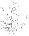
- FIG. 1 the top view of the lock system (1), which is the subject of the invention, is given while the door (2) is in closed position.
- the door (2) mounted on the wall (3) via the hinge (2.2) seems to be closed via the lock bolt (2.1) on the other side.
- the said lock system (1) comprises a piston (7), which is connected to the door (2) via a juncture point (11) placed at the backside of the door (2), and which is connected to the wall (3) that is in crosswise position with the door (2), via another juncture point (11).
- Fluid (8) material is found inside the said piston (7), and due to the motion of the movable part (7.1) inside the piston (7) and since this fluid (8) can not be compacted, it goes between the front and rear chambers (7.3, 7.4) of the piston (7) by passing through the pipe (10).
- FIG-2 the top view of the lock system (1), which is the subject of the invention, is given while the door (2) is in open position.
- a person who opens the lock bolt (2.1) by holding the door (2) from the handle (2.3), pushes the door (2) towards inside in order to enter.
- This pushing movement causes the starting handle (7.2) connected to the door (2) via a juncture point (11) placed at the backside of the door (2), and the movable part (7.1) connected this starting handle, be pushed ahead. Therefore, the fluid (8) found inside the piston (7) moves from the rear chamber (7.4) to the front chamber (7.3) by passing through the pipe (10).
- the valve (9) placed on the pipe (10) has to be left open.
- FIG-3 the schematic view of the remote control device (4) of the lock system (1), which is the subject of the invention, is given.
- the ON (13.1) and OFF (13.2) modes of the control and encryption unit (13) is shown here.
- the lock system (1) works as described below.
- Code is sent to the control unit (5) using the remote control device (4), which operates via radio frequency (RF).
- the microcontroller (5.1) located in the said control unit (5) decodes the code coming from the remote control device (4) and received via RF receiver module (5.3), and if the code is correct, then transmits it to the motor driver and position detector (5.2).
- the invention is a lock system (1) developed for providing security, and it is characterized in that; it comprises:
- the said lock system (1) also comprises a feed and accumulator charging unit (12) in order to provide the required energy for operation of the system (1) and in order to charge the accumulator.
Landscapes
- Engineering & Computer Science (AREA)
- Computer Networks & Wireless Communication (AREA)
- Lock And Its Accessories (AREA)
Applications Claiming Priority (1)
| Application Number | Priority Date | Filing Date | Title |
|---|---|---|---|
| TR200900391 | 2009-05-01 |
Publications (1)
| Publication Number | Publication Date |
|---|---|
| EP2246511A1 true EP2246511A1 (de) | 2010-11-03 |
Family
ID=42635073
Family Applications (1)
| Application Number | Title | Priority Date | Filing Date |
|---|---|---|---|
| EP10004265A Withdrawn EP2246511A1 (de) | 2009-05-01 | 2010-04-22 | Türschliesser |
Country Status (1)
| Country | Link |
|---|---|
| EP (1) | EP2246511A1 (de) |
Citations (8)
| Publication number | Priority date | Publication date | Assignee | Title |
|---|---|---|---|---|
| FR2409363A1 (fr) * | 1977-11-22 | 1979-06-15 | Belin Jacques | Dispositif electropneumatique pour manoeuvrer automatiquement un portail ou analogue par radio-commande |
| US5050346A (en) * | 1990-07-30 | 1991-09-24 | Eccleston Jon E | Automatic operating system for swinging door |
| TR200403488U (tr) | 2004-12-17 | 2005-06-21 | Al Nalburi̇ye Hirdavat Ti̇c. Ve San. Ltd. Şti̇. | Elektrik motor tahrikli tam otomatik-elektronik açılıp kapanabilen kapı kilitleme sistemi. |
| EP1509823B1 (de) | 2002-06-06 | 2005-10-26 | Mhouse Srl | Elektrisches system zur steuerung mindestens eines tors oder einer tür oder eines ähnlichen elements des elektrisch bewegten typs |
| TR200603216U (tr) | 2006-06-26 | 2006-09-21 | Mostek Elektroni̇k Bi̇lgi̇sayar San. Ti̇c. Ltd. Şti̇. | Kapı ve hareketli mekanizmalarda çalışan elektrikli otomat. |
| EP1747339B1 (de) | 2004-05-12 | 2007-12-19 | Dorma Gmbh & Co. Kg | Schiebetürsystem mit einer in einem kämpfer angeordneten antriebsvorrichtung |
| US20080115543A1 (en) * | 2006-11-17 | 2008-05-22 | Electronics And Telecommunications Research Institute | Door management system for field service and delivery personnel |
| TR200803041U (tr) | 2008-05-01 | 2008-12-22 | Veldo Mekani̇k Ve Bi̇li̇şi̇m Teknoloji̇leri̇ Geli̇şti̇rme Ve Danişmanlik Sanayi̇ Ve Ti̇caret Li̇mi̇ted Şi̇rketi̇ | Ticari araçlarda manuel kullanılan kayar kapıları otomatik açan ve kapatan otomatik kapı sistemi |
-
2010
- 2010-04-22 EP EP10004265A patent/EP2246511A1/de not_active Withdrawn
Patent Citations (8)
| Publication number | Priority date | Publication date | Assignee | Title |
|---|---|---|---|---|
| FR2409363A1 (fr) * | 1977-11-22 | 1979-06-15 | Belin Jacques | Dispositif electropneumatique pour manoeuvrer automatiquement un portail ou analogue par radio-commande |
| US5050346A (en) * | 1990-07-30 | 1991-09-24 | Eccleston Jon E | Automatic operating system for swinging door |
| EP1509823B1 (de) | 2002-06-06 | 2005-10-26 | Mhouse Srl | Elektrisches system zur steuerung mindestens eines tors oder einer tür oder eines ähnlichen elements des elektrisch bewegten typs |
| EP1747339B1 (de) | 2004-05-12 | 2007-12-19 | Dorma Gmbh & Co. Kg | Schiebetürsystem mit einer in einem kämpfer angeordneten antriebsvorrichtung |
| TR200403488U (tr) | 2004-12-17 | 2005-06-21 | Al Nalburi̇ye Hirdavat Ti̇c. Ve San. Ltd. Şti̇. | Elektrik motor tahrikli tam otomatik-elektronik açılıp kapanabilen kapı kilitleme sistemi. |
| TR200603216U (tr) | 2006-06-26 | 2006-09-21 | Mostek Elektroni̇k Bi̇lgi̇sayar San. Ti̇c. Ltd. Şti̇. | Kapı ve hareketli mekanizmalarda çalışan elektrikli otomat. |
| US20080115543A1 (en) * | 2006-11-17 | 2008-05-22 | Electronics And Telecommunications Research Institute | Door management system for field service and delivery personnel |
| TR200803041U (tr) | 2008-05-01 | 2008-12-22 | Veldo Mekani̇k Ve Bi̇li̇şi̇m Teknoloji̇leri̇ Geli̇şti̇rme Ve Danişmanlik Sanayi̇ Ve Ti̇caret Li̇mi̇ted Şi̇rketi̇ | Ticari araçlarda manuel kullanılan kayar kapıları otomatik açan ve kapatan otomatik kapı sistemi |
Similar Documents
| Publication | Publication Date | Title |
|---|---|---|
| US6581332B1 (en) | Remote controllable device for opening/closing of a window | |
| US7315143B2 (en) | Operating system utilizing a selectively concealed multi-function wall station transmitter with an auto-close function for a motorized barrier operator | |
| KR101744888B1 (ko) | 창문의 잠금장치 | |
| CN203430207U (zh) | 一种遥控门禁系统 | |
| CN110067452B (zh) | 一种户外电气柜 | |
| EP2246511A1 (de) | Türschliesser | |
| JP2006125149A (ja) | 引き違いサッシ | |
| WO2004033832A3 (fr) | Dispositif de commande d'ouverture d'ouvrants de vehicule automobile | |
| US20180347243A1 (en) | Double door latch and lock assembly | |
| CN202560015U (zh) | 智控保险门 | |
| EP2148029A1 (de) | Automatisches Schloss | |
| KR20160146416A (ko) | 창문의 잠금장치 | |
| CN208330149U (zh) | 一种车库用智能防盗卷帘门 | |
| CN208564276U (zh) | 一种防夹安全门 | |
| CN201062475Y (zh) | 一种内封闭防撬门 | |
| CN201045250Y (zh) | 密码遥控防盗门锁主栓止退器 | |
| WO2005088046A1 (en) | Lock mechanism | |
| CN202417061U (zh) | 一种门锁 | |
| CN221546694U (zh) | 一种银行防尾随联动门 | |
| CN209457555U (zh) | 一种基于NB-IoT的物联网智能锁具 | |
| CN219012317U (zh) | 一种汽车门开关装置及其汽车门、汽车 | |
| US20080168713A1 (en) | Remote controlled overhead garage door locking mechanism | |
| CN200975191Y (zh) | 智能遥控防盗门 | |
| CN201916585U (zh) | 遥控阀门锁 | |
| EP2672465A1 (de) | Vorrichtung zum Antrieb eines Schliessblech |
Legal Events
| Date | Code | Title | Description |
|---|---|---|---|
| PUAI | Public reference made under article 153(3) epc to a published international application that has entered the european phase |
Free format text: ORIGINAL CODE: 0009012 |
|
| AK | Designated contracting states |
Kind code of ref document: A1 Designated state(s): AT BE BG CH CY CZ DE DK EE ES FI FR GB GR HR HU IE IS IT LI LT LU LV MC MK MT NL NO PL PT RO SE SI SK SM TR |
|
| AX | Request for extension of the european patent |
Extension state: AL BA ME RS |
|
| RAP1 | Party data changed (applicant data changed or rights of an application transferred) |
Owner name: KIVRAK, ENGIN |
|
| RIN1 | Information on inventor provided before grant (corrected) |
Inventor name: KIVRAK, ENGIN |
|
| STAA | Information on the status of an ep patent application or granted ep patent |
Free format text: STATUS: THE APPLICATION IS DEEMED TO BE WITHDRAWN |
|
| 18D | Application deemed to be withdrawn |
Effective date: 20110504 |