EP2246528B1 - Ladungsverteilungssystem für einen Gasturbinenmotor - Google Patents
Ladungsverteilungssystem für einen Gasturbinenmotor Download PDFInfo
- Publication number
- EP2246528B1 EP2246528B1 EP10250676.3A EP10250676A EP2246528B1 EP 2246528 B1 EP2246528 B1 EP 2246528B1 EP 10250676 A EP10250676 A EP 10250676A EP 2246528 B1 EP2246528 B1 EP 2246528B1
- Authority
- EP
- European Patent Office
- Prior art keywords
- pressure
- gas turbine
- turbine engine
- line
- actuator
- Prior art date
- Legal status (The legal status is an assumption and is not a legal conclusion. Google has not performed a legal analysis and makes no representation as to the accuracy of the status listed.)
- Active
Links
Images

Classifications
-
- F—MECHANICAL ENGINEERING; LIGHTING; HEATING; WEAPONS; BLASTING
- F01—MACHINES OR ENGINES IN GENERAL; ENGINE PLANTS IN GENERAL; STEAM ENGINES
- F01D—NON-POSITIVE DISPLACEMENT MACHINES OR ENGINES, e.g. STEAM TURBINES
- F01D25/00—Component parts, details, or accessories, not provided for in, or of interest apart from, other groups
- F01D25/16—Arrangement of bearings; Supporting or mounting bearings in casings
- F01D25/166—Sliding contact bearing
- F01D25/168—Sliding contact bearing for axial load mainly
-
- F—MECHANICAL ENGINEERING; LIGHTING; HEATING; WEAPONS; BLASTING
- F01—MACHINES OR ENGINES IN GENERAL; ENGINE PLANTS IN GENERAL; STEAM ENGINES
- F01D—NON-POSITIVE DISPLACEMENT MACHINES OR ENGINES, e.g. STEAM TURBINES
- F01D3/00—Machines or engines with axial-thrust balancing effected by working-fluid
- F01D3/04—Machines or engines with axial-thrust balancing effected by working-fluid axial thrust being compensated by thrust-balancing dummy piston or the like
-
- F—MECHANICAL ENGINEERING; LIGHTING; HEATING; WEAPONS; BLASTING
- F16—ENGINEERING ELEMENTS AND UNITS; GENERAL MEASURES FOR PRODUCING AND MAINTAINING EFFECTIVE FUNCTIONING OF MACHINES OR INSTALLATIONS; THERMAL INSULATION IN GENERAL
- F16C—SHAFTS; FLEXIBLE SHAFTS; ELEMENTS OR CRANKSHAFT MECHANISMS; ROTARY BODIES OTHER THAN GEARING ELEMENTS; BEARINGS
- F16C41/00—Other accessories, e.g. devices integrated in the bearing not relating to the bearing function as such
- F16C41/02—Arrangements for equalising the load on a plurality of bearings or their elements
-
- F—MECHANICAL ENGINEERING; LIGHTING; HEATING; WEAPONS; BLASTING
- F05—INDEXING SCHEMES RELATING TO ENGINES OR PUMPS IN VARIOUS SUBCLASSES OF CLASSES F01-F04
- F05D—INDEXING SCHEME FOR ASPECTS RELATING TO NON-POSITIVE-DISPLACEMENT MACHINES OR ENGINES, GAS-TURBINES OR JET-PROPULSION PLANTS
- F05D2260/00—Function
- F05D2260/50—Kinematic linkage, i.e. transmission of position
- F05D2260/57—Kinematic linkage, i.e. transmission of position using servos, independent actuators, etc.
-
- F—MECHANICAL ENGINEERING; LIGHTING; HEATING; WEAPONS; BLASTING
- F05—INDEXING SCHEMES RELATING TO ENGINES OR PUMPS IN VARIOUS SUBCLASSES OF CLASSES F01-F04
- F05D—INDEXING SCHEME FOR ASPECTS RELATING TO NON-POSITIVE-DISPLACEMENT MACHINES OR ENGINES, GAS-TURBINES OR JET-PROPULSION PLANTS
- F05D2270/00—Control
- F05D2270/60—Control system actuates means
- F05D2270/65—Pneumatic actuators
-
- F—MECHANICAL ENGINEERING; LIGHTING; HEATING; WEAPONS; BLASTING
- F16—ENGINEERING ELEMENTS AND UNITS; GENERAL MEASURES FOR PRODUCING AND MAINTAINING EFFECTIVE FUNCTIONING OF MACHINES OR INSTALLATIONS; THERMAL INSULATION IN GENERAL
- F16C—SHAFTS; FLEXIBLE SHAFTS; ELEMENTS OR CRANKSHAFT MECHANISMS; ROTARY BODIES OTHER THAN GEARING ELEMENTS; BEARINGS
- F16C2360/00—Engines or pumps
- F16C2360/23—Gas turbine engines
Definitions
- the application relates generally to gas turbine engines and, more particularly, to a load distribution system for bearings supporting a gas turbine engine main shaft.
- the turbine engine low pressure rotor is subjected to aerodynamic axial forces, typically oriented backward due to the high reaction degree of the low pressure turbine and the low reaction degree of the fan.
- the aerodynamic axial forces are the result of the air pressure distribution over the rotor surface area.
- one axial bearing is installed to react to the rotor axial forces.
- the axial bearings supporting the rotor may not be proportionally loaded. This may result in a premature wear of the axial bearings supporting the rotor.
- a gas turbine engine of the type having a high pressure rotor and a low pressure rotor and a method of balancing loads on axial bearings supporting a low pressure rotor in a gas turbine with the features of the preamble of claims 1 and 9 is disclosed in EP 2 050 932 .
- Another gas turbine engine and method of the same is disclosed in US 4,907,943 .
- a gas turbine engine of the type having a high pressure rotor and a low pressure rotor comprising: at least a fixed axial bearing and a floating axial bearing, the fixed axial bearing being fixed to a casing of the gas turbine engine, the floating axial bearing being operatively connected to the gas turbine engine so as to be axially displaceable relative to the casing ; a load distribution system comprising a line having an inlet end positioned in a high-pressure compressor gas path downstream of any compressor stage provided with a variable geometry, and adapted to sense static pressure from the gas path, and an outlet end producing the static pressure; and a pressure actuator positioned at the outlet end and connected to the floating axial bearing to exert a force on the floating axial bearing proportionally to a pressure of the static pressure to adjust the axial position of the floating axial bearing along the rotor; whereby an axial load on the low pressure rotor is distributed between the axial bearings supporting the rotor.
- a method for balancing loads on axial bearings supporting a low pressure rotor in a gas turbine engine comprising: providing a line having an inlet end exposed to a high-pressure compressor gas path downstream of any compressor stage provided with a variable geometry, and an outlet end adjacent to a floating axial bearing, and a pressure actuator in the outlet end connected to the floating axial bearing; subjecting the inlet end of the line to the gas path, whereby the inlet end and the outlet end are subjected to the same static pressure; and exerting a force on the floating axial bearing with the pressure actuator as a result of the pressure differential between an inside exposed to the static pressure, and an outside of the actuator.
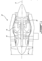
- Fig. 1 illustrates a turbofan gas turbine engine 10 of a type preferably provided for use in subsonic flight, generally comprising in serial flow communication a fan 12 through which ambient air is propelled, a multistage compressor 14 for pressurizing the air, a combustor 16 in which the compressed air is mixed with fuel and ignited for generating an annular stream of hot combustion gases, and a turbine section 18 for extracting energy from the combustion gases.
- the gas turbine engine 10 is equipped with a load distribution system 20.
- the load distribution system 20 is provided to distribute the axial load sustained by bearings supporting the low pressure spool or rotor 21 in the engine 10.
- the low pressure rotor 21 is radially and axially supported at the front by fixed axial bearing 22 and by floating axial bearing 24, although the rotor 21 may have more than two axial bearings.
- the outer race of the fixed axial bearing 22 is in a fixed axial position relative to the static engine casing.
- the floating axial bearing 24 is axially displaceable (i.e., axially floating) with respect to the static engine casing. More specifically, the floating axial bearing 24 is connected to a pneumatic actuator 26. The outer race of the floating axial bearing 24 is connected to the engine 10 by an appropriate arrangement enabling the axial movement thereof. For instance, a squeezed oil-film damper arrangement 28 may be used to allow the axial movement of the floating axial bearing 24 with respect to the engine casing.
- the pneumatic actuator 26 is installed on the engine fixed casing or is an integral part thereof.
- the pneumatic actuator 26 may comprise a sealed ring circumferentially positioned about the rotor 21.
- the sealed ring of the pneumatic actuator 26 acts as a piston exposed to pressurized air at an outlet end of a pressure line 30.
- the pneumatic actuator 26 may use a tandem piston arrangement, or metallic bellows, amongst other possibilities.
- the pneumatic actuator 26 is air-tight such that the pressure line 30 has no net positive flow, i.e. the pressure line 30 is a pressure sensing line.
- the pneumatic actuator 26 may have a device to preload the piston, such as a spring, a diaphragm, or the like. The device performs a constant preload on the piston (e.g., 20% of the maximum force) so as to preclude force reversal on the bearing 22.
- the pressure line 30 has an inlet end positioned in the main gas path 32 of the gas turbine engine 10, so as to sense the local static pressure.
- the inlet is positioned at a location downstream of the compressor stages of variable geometry, such as the variable inlet guide vanes, the handling bleed valves, and the low-pressure cabin bleed port, which location provides a static pressure consistently proportional to the high-pressure compressor pressure ratio.
- the inlet may be installed downstream of the high pressure turbine and upstream of the low pressure turbine because there is no flow in the pressure line 30, hence the actuator end of the pressure line 30 remains at a same temperature.
- the inlet end of the pressure line 30 may be upstream of the low pressure turbine as there is low pressure available downstream of the low pressure turbine.
- One such location is the inlet of the combustor chamber.
- the variation of pressure with the engine regime i.e., engine power and flight conditions at the location is sufficient to actuate the pneumatic actuator 26 in providing the thrust force to the floating bearing 24 required to balance a portion of the low pressure rotor axial force such that the fixed bearing 22 supports the rest of the axial force. Accordingly, by collecting gas in the gas path of the engine 10, the pressure of the gas is proportional to the pressure distribution in the gas path, and hence is proportional to the axial forces exerted on the rotor 21.
- the pressurized gas actuates the pneumatic actuator 26 with the gas collected by the inlet end in the gas path 32.
- the pneumatic actuator 26 will be displaced on a relatively small distance sufficient to compensate for the total backlash on the bearing 24 and 22 as well as for differential thermal expansion between engine casings and the low pressure rotor 21.
- the pneumatic actuator 26 will exert a force on the floating axial bearing 24 that is proportional to this pressure differential.
- the pressure differential is proportional to the aerodynamic forces acting upon the rotor 21, which forces are dependent on engine power and ambient conditions (e.g., altitude). Accordingly, the axial load is distributed in a generally constant ratio for any engine regime.
- the load distribution system 20 provides a proportional axial load distribution between bearings 22 and 24 at any engine power or for any ambient conditions, without requiring any external pressure regulating system or any continuous air flow. As a result, there is a negligible pressure loss in the gas path, and therefore a negligible effect on the fuel consumption of the engine 10. If a tandem piston arrangement is used as an alternative to the sealed ring piston, pressurized gas from a lower pressure location (i.e., cooler gas) may be used to operate the pneumatic actuator 26.
- a pressure indicator 34 and a temperature indicator 36 are provided in the pressure line 30, so as to measure parameters associated with the actuation of the pneumatic actuator 26.
- the pressure indicator 34 provides a visual indication that the pneumatic actuator 26 receives the correct pressure. More specifically, if the pneumatic actuator 26 is air tight, then there should be no air flow through the pressure line 30 under steady state conditions. If a pressure loss is detected by the pressure indicator 34, there is a major leakage at the pneumatic actuator 26, or at any point between the inlet and the pressure actuator 26 in the pressure line 30. Moreover, the absence of an air flow through the pressure line 30 results in the pressure line 30 temperature being colder than that in the gas path 32.
- the temperature indicator 36 can therefore be used to detect leakage of the pneumatic actuator 26, by indicating a temperature increase resulting from hot gas flowing through the pressure line 30.
- a temperature variation as measured by the temperature indicator 36 is an indication of a minor leakage at the pressure actuator 26, requiring maintenance.
- the pressure indicator 34 may be connected to the pressure line 30 adjacent to the pneumatic actuator 26, whereas the temperature indicator 36 may be at an intermediary position, or any other suitable position, along the pressure line 30.
- the displays of the indicators 34 and 36 are at a visible location, for instance to allow a simple visual check. Any appropriate technology may be used as part of the pressure indicator 34 and the temperature indicator 36 to measure pressure and temperature, respectively.
- the pressure indicator 34 may be a tension-sensitive fastener or a pressure switch, amongst other alternatives, while the thermal indicator 36 may be an off-the-shelf gas furnace pilot flame thermal switch.
Landscapes
- Engineering & Computer Science (AREA)
- General Engineering & Computer Science (AREA)
- Mechanical Engineering (AREA)
- Magnetic Bearings And Hydrostatic Bearings (AREA)
- Support Of The Bearing (AREA)
- Structures Of Non-Positive Displacement Pumps (AREA)
Claims (12)
- Gasturbinenmotor (10) der Art, die einen Hochdruckrotor und einen Niederdruckrotor aufweist, wobei der Niederdruckrotor (21) Folgendes umfasst:mindestens ein festes axiales Lager (22) und ein schwimmendes axiales Lager (24), wobei das feste axiale Lager (22) an einem Gehäuse des Gasturbinenmotors (10) befestigt ist, das schwimmende axiale Lager (24) in Wirkverbindung mit dem Gasturbinenmotor (10) steht, so dass es axial in Bezug auf das Gehäuse verschiebbar ist;ein Ladungsverteilungssystem (20), das eine Leitung (30) umfasst, die eine Austrittsseite aufweist, die einen statischen Druck erzeugt; und einen Drucksteller (26), der an der Austrittsseite angeordnet ist und mit dem schwimmenden axialen Lager (24) verbunden ist, um eine Kraft auf das schwimmende axiale Lager (24) proportional zu einem Druck des statischen Drucks auszuüben, um die axiale Position des schwimmenden axialen Lagers (24) entlang des Rotors anzupassen;wobei eine axiale Last auf dem Niederdruckrotor (21) zwischen den axialen Lagern (22, 24), die den Rotor (21) stützen, verteilt wird;dadurch gekennzeichnet, dass die Leitung (30) eine Eintrittsseite aufweist, die in einem Hochdruckverdichter-Gasweg nach jeder Verdichterstufe mit einer variablen Geometrie angeordnet ist und den statischen Druck vom Gasweg erfasst.
- Gasturbinenmotor nach Anspruch 1, wobei der Drucksteller (26) einen ringförmigen Kolben aufweist, der geeignet ist, um mit dem axialen Lager (24) verbunden zu werden, wobei der Kolben mit der Austrittsseite verbunden ist, um sich in Abhängigkeit eines Drucks in der Leitung (30) zu bewegen.
- Gasturbinenmotor nach Anspruch 1 oder 2, wobei das schwimmende axiale Lager (24) in Wirkverbindung mit dem Gasturbinenmotor (10) durch einen Ölfilmdämpfer (28) steht.
- Gasturbinenmotor nach einem der vorstehenden Ansprüche, weiter umfassend eine Vorspannvorrichtung umfasst, um den Drucksteller (26) an der Austrittsseite vorzuspannen oder die Kraft, die vom Drucksteller (26) an der Austrittsseite bereitgestellt wird, um eine konstante Größe zu verringern, um die Bewegung des Stellers (26) zu ermöglichen, wenn ein vorgegebener Druck erreicht ist.
- Gasturbinenmotor nach einem der vorstehenden Ansprüche, weiter umfassend einen Druckanzeiger (34), der mit der Leitung (30) verbunden ist, um einen Druckverlust anzuzeigen, um auf eine Undichtigkeit im Drucksteller oder in der Leitung (30) an irgendeinem Punkt zwischen dem Einlass und dem Drucksteller (26) hinzuweisen.
- Gasturbinenmotor nach einem der vorstehenden Ansprüche, weiter umfassend einen Temperaturanzeiger (36), der mit der Leitung (30) verbunden ist, um einen Temperaturanstieg in der Leitung (30) anzuzeigen, um auf eine Undichtigkeit im Drucksteller (26) hinzuweisen.
- Gasturbinenmotor nach einem der vorstehenden Ansprüche, wobei die Eintrittsseite der Leitung (30) vor der Niederdruckturbine des Gasturbinenmotors (10) angeordnet ist.
- Gasturbinenmotor nach Anspruch 7, wobei sich die Einlassseite am Einlass der Brennkammer (16) befindet.
- Verfahren zum Ausgleichen von Lasten auf axialen Lagern (22, 24), die einen Niederdruckrotor (21) in einem Gasturbinenmotor (10) stützen, umfassend:Bereitstellen einer Leitung (30), die eine Einlassseite und eine Austrittsseite aufweist, die an ein schwimmendes axiales Lager (24) angrenzt, und eines Druckstellers (26) in der Austrittsseite, der mit dem schwimmenden axialen Lager (24) verbunden ist;Aussetzen der Einlassseite der Leitung (30) dem Gasweg, wobei die Einlassseite und die Austrittsseite demselben statischen Druck ausgesetzt sind; undAusüben einer Kraft auf das schwimmende axiale Lager (24) mit dem Drucksteller (26) infolge der Druckdifferenz zwischen einer Innenseite, die dem statischen Druck ausgesetzt ist, und einer Außenseite des Stellers (26),dadurch gekennzeichnet, dass die Einlassseite einem Hochdruckverdichter-Gasweg nach jeder Verdichterstufe mit einer variablen Geometrie ausgesetzt ist.
- Verfahren nach Anspruch 9, weiter umfassend das Vorspannen des Druckstellers (26) vor dem Aussetzen des Druckstellers (26) der Druckdifferenz, so dass eine Gesamtkraft des Druckstellers eine Vorspannkraft für den Drucksteller (26) für eine Bewegung überschreiten muss.
- Verfahren nach Anspruch 9 oder 10, weiter umfassend das Anzeigen eines Vorliegens einer Undichtigkeit im Drucksteller (26) oder in der Leitung (30) an irgendeinem Punkt zwischen der Einlassseite und dem Drucksteller (26) durch Anzeigen eines Druckverlusts, der in der Leitung (30) gemessen wurde.
- Verfahren nach Anspruch 9, 10 oder 11, weiter umfassend das Anzeigen eines Vorliegens einer Undichtigkeit im Drucksteller (26) durch Anzeigen eines Temperaturanstiegs, der in der Leitung (30) gemessen wurde.
Applications Claiming Priority (1)
| Application Number | Priority Date | Filing Date | Title |
|---|---|---|---|
| US12/429,234 US8182201B2 (en) | 2009-04-24 | 2009-04-24 | Load distribution system for gas turbine engine |
Publications (3)
| Publication Number | Publication Date |
|---|---|
| EP2246528A2 EP2246528A2 (de) | 2010-11-03 |
| EP2246528A3 EP2246528A3 (de) | 2014-05-14 |
| EP2246528B1 true EP2246528B1 (de) | 2018-09-12 |
Family
ID=42289031
Family Applications (1)
| Application Number | Title | Priority Date | Filing Date |
|---|---|---|---|
| EP10250676.3A Active EP2246528B1 (de) | 2009-04-24 | 2010-03-31 | Ladungsverteilungssystem für einen Gasturbinenmotor |
Country Status (3)
| Country | Link |
|---|---|
| US (1) | US8182201B2 (de) |
| EP (1) | EP2246528B1 (de) |
| CA (1) | CA2701512C (de) |
Families Citing this family (5)
| Publication number | Priority date | Publication date | Assignee | Title |
|---|---|---|---|---|
| EP2971607B1 (de) | 2013-03-13 | 2019-06-26 | United Technologies Corporation | Schubausgleich für lüfterantrieb |
| GB201421880D0 (en) * | 2014-12-09 | 2015-01-21 | Rolls Royce Plc | Bearing structure |
| GB201421881D0 (en) * | 2014-12-09 | 2015-01-21 | Rolls Royce Plc | Bearing structure |
| US11859547B2 (en) * | 2022-02-25 | 2024-01-02 | General Electric Company | Turbine engine having a balance cavity |
| US12196132B1 (en) | 2023-12-21 | 2025-01-14 | Pratt & Whitney Canada Corp. | System and method for preloading a bearing |
Family Cites Families (20)
| Publication number | Priority date | Publication date | Assignee | Title |
|---|---|---|---|---|
| US2647684A (en) * | 1947-03-13 | 1953-08-04 | Rolls Royce | Gas turbine engine |
| US3433020A (en) * | 1966-09-26 | 1969-03-18 | Gen Electric | Gas turbine engine rotors |
| CH633355A5 (de) * | 1978-08-04 | 1982-11-30 | Bbc Brown Boveri & Cie | Achsdrucklageranordnung. |
| US4306834A (en) * | 1979-06-25 | 1981-12-22 | Westinghouse Electric Corp. | Balance piston and seal for gas turbine engine |
| US4697981A (en) * | 1984-12-13 | 1987-10-06 | United Technologies Corporation | Rotor thrust balancing |
| US4864810A (en) * | 1987-01-28 | 1989-09-12 | General Electric Company | Tractor steam piston balancing |
| US4907943A (en) * | 1988-05-25 | 1990-03-13 | United Technologies Corporation | Method and apparatus for assessing thrust loads on engine bearings |
| CA1326476C (en) * | 1988-09-30 | 1994-01-25 | Vaclav Kulle | Gas compressor having dry gas seals for balancing end thrust |
| US4969797A (en) * | 1989-03-22 | 1990-11-13 | Matsushita Electric Industrial Co., Ltd. | Fan motor |
| US5141389A (en) * | 1990-03-20 | 1992-08-25 | Nova Corporation Of Alberta | Control system for regulating the axial loading of a rotor of a fluid machine |
| CH684495A5 (de) * | 1991-09-04 | 1994-09-30 | Escher Wyss Ag | Turbomaschine. |
| US5791868A (en) * | 1996-06-14 | 1998-08-11 | Capstone Turbine Corporation | Thrust load compensating system for a compliant foil hydrodynamic fluid film thrust bearing |
| US5862666A (en) * | 1996-12-23 | 1999-01-26 | Pratt & Whitney Canada Inc. | Turbine engine having improved thrust bearing load control |
| US6067791A (en) * | 1997-12-11 | 2000-05-30 | Pratt & Whitney Canada Inc. | Turbine engine with a thermal valve |
| US6457933B1 (en) * | 2000-12-22 | 2002-10-01 | General Electric Company | Methods and apparatus for controlling bearing loads within bearing assemblies |
| GB0304320D0 (en) * | 2003-02-26 | 2003-04-02 | Bladon Jets Ltd | Gas turbine engines |
| DE10358625A1 (de) * | 2003-12-11 | 2005-07-07 | Rolls-Royce Deutschland Ltd & Co Kg | Anordnung zur Lagerentlastung in einer Gasturbine |
| US20070122265A1 (en) * | 2005-11-30 | 2007-05-31 | General Electric Company | Rotor thrust balancing apparatus and method |
| EP2011963B1 (de) * | 2007-07-04 | 2018-04-04 | Ansaldo Energia Switzerland AG | Verfahren zum Betrieb einer Gasturbine mit Axialschubausgleich |
| GB0720628D0 (en) * | 2007-10-20 | 2007-11-28 | Rolls Royce Plc | Bearing arrangement |
-
2009
- 2009-04-24 US US12/429,234 patent/US8182201B2/en active Active
-
2010
- 2010-03-31 EP EP10250676.3A patent/EP2246528B1/de active Active
- 2010-04-23 CA CA2701512A patent/CA2701512C/en not_active Expired - Fee Related
Non-Patent Citations (1)
| Title |
|---|
| None * |
Also Published As
| Publication number | Publication date |
|---|---|
| CA2701512C (en) | 2017-08-22 |
| US8182201B2 (en) | 2012-05-22 |
| CA2701512A1 (en) | 2010-10-24 |
| EP2246528A3 (de) | 2014-05-14 |
| US20100272556A1 (en) | 2010-10-28 |
| EP2246528A2 (de) | 2010-11-03 |
Similar Documents
| Publication | Publication Date | Title |
|---|---|---|
| US10794275B2 (en) | Multi-circuit buffer system for a gas turbine engine | |
| EP3536901B1 (de) | Schubsteuerung eines gelagerten rotors | |
| EP2809910B1 (de) | Gasturbinentriebwerkspuffersystem | |
| EP3040567B1 (de) | Lageranordnung mit zwei wälzlagern und druckkammern zum vorspannen der wälzlager und zum gleichmässigen verteilen der axiallast auf beide lager | |
| EP2246528B1 (de) | Ladungsverteilungssystem für einen Gasturbinenmotor | |
| US10533437B2 (en) | Inner diffuser case for a gas turbine engine | |
| EP3040568B1 (de) | Lageranordnung mit zwei nebeneinander angeordneten wälzlagern und einer druckkammer mit federnder wand zum vorspannen der wälzlager und zum gleichmässigen verteilen der axiallast auf beide lager | |
| US20150252731A1 (en) | Gas turbine engine including bleed system coupled to upstream and downstream locations of compressor | |
| CN107120190A (zh) | 涡轮发动机喷射器喉部控制 | |
| CN109563744B (zh) | 带有吸气面密封的涡轮发动机 | |
| US10513938B2 (en) | Intershaft compartment buffering arrangement | |
| EP3792466B1 (de) | Zustandsmonitor für ein schaltventil eines gasturbinenzapfluftsystems | |
| US10161314B2 (en) | Vented buffer air supply for intershaft seals | |
| CN111322119A (zh) | 带有浮动护罩的涡轮发动机 | |
| Cline et al. | High pressure compressor component performance report | |
| US10337739B2 (en) | Combustion bypass passive valve system for a gas turbine | |
| Attia et al. | The Predicted and Measured Effects of Increasing Back Pressure on the Performance of a Turboshaft Engine | |
| Mcanally et al. | Shrouded Impeller Test Program | |
| Strohl | Hot Streaks and Deformation |
Legal Events
| Date | Code | Title | Description |
|---|---|---|---|
| PUAI | Public reference made under article 153(3) epc to a published international application that has entered the european phase |
Free format text: ORIGINAL CODE: 0009012 |
|
| AK | Designated contracting states |
Kind code of ref document: A2 Designated state(s): AT BE BG CH CY CZ DE DK EE ES FI FR GB GR HR HU IE IS IT LI LT LU LV MC MK MT NL NO PL PT RO SE SI SK SM TR |
|
| AX | Request for extension of the european patent |
Extension state: AL BA ME RS |
|
| PUAL | Search report despatched |
Free format text: ORIGINAL CODE: 0009013 |
|
| AK | Designated contracting states |
Kind code of ref document: A3 Designated state(s): AT BE BG CH CY CZ DE DK EE ES FI FR GB GR HR HU IE IS IT LI LT LU LV MC MK MT NL NO PL PT RO SE SI SK SM TR |
|
| AX | Request for extension of the european patent |
Extension state: AL BA ME RS |
|
| RIC1 | Information provided on ipc code assigned before grant |
Ipc: F01D 25/16 20060101AFI20140410BHEP Ipc: F01D 3/04 20060101ALI20140410BHEP |
|
| 17P | Request for examination filed |
Effective date: 20141114 |
|
| RBV | Designated contracting states (corrected) |
Designated state(s): AT BE BG CH CY CZ DE DK EE ES FI FR GB GR HR HU IE IS IT LI LT LU LV MC MK MT NL NO PL PT RO SE SI SK SM TR |
|
| RIC1 | Information provided on ipc code assigned before grant |
Ipc: F01D 3/04 20060101ALI20180131BHEP Ipc: F01D 25/16 20060101AFI20180131BHEP Ipc: F16C 41/02 20060101ALI20180131BHEP |
|
| GRAP | Despatch of communication of intention to grant a patent |
Free format text: ORIGINAL CODE: EPIDOSNIGR1 |
|
| STAA | Information on the status of an ep patent application or granted ep patent |
Free format text: STATUS: GRANT OF PATENT IS INTENDED |
|
| INTG | Intention to grant announced |
Effective date: 20180327 |
|
| GRAS | Grant fee paid |
Free format text: ORIGINAL CODE: EPIDOSNIGR3 |
|
| GRAA | (expected) grant |
Free format text: ORIGINAL CODE: 0009210 |
|
| STAA | Information on the status of an ep patent application or granted ep patent |
Free format text: STATUS: THE PATENT HAS BEEN GRANTED |
|
| AK | Designated contracting states |
Kind code of ref document: B1 Designated state(s): AT BE BG CH CY CZ DE DK EE ES FI FR GB GR HR HU IE IS IT LI LT LU LV MC MK MT NL NO PL PT RO SE SI SK SM TR |
|
| REG | Reference to a national code |
Ref country code: GB Ref legal event code: FG4D |
|
| REG | Reference to a national code |
Ref country code: CH Ref legal event code: EP |
|
| REG | Reference to a national code |
Ref country code: IE Ref legal event code: FG4D |
|
| REG | Reference to a national code |
Ref country code: DE Ref legal event code: R096 Ref document number: 602010053489 Country of ref document: DE |
|
| REG | Reference to a national code |
Ref country code: AT Ref legal event code: REF Ref document number: 1040835 Country of ref document: AT Kind code of ref document: T Effective date: 20181015 |
|
| REG | Reference to a national code |
Ref country code: NL Ref legal event code: MP Effective date: 20180912 |
|
| REG | Reference to a national code |
Ref country code: LT Ref legal event code: MG4D |
|
| PG25 | Lapsed in a contracting state [announced via postgrant information from national office to epo] |
Ref country code: SE Free format text: LAPSE BECAUSE OF FAILURE TO SUBMIT A TRANSLATION OF THE DESCRIPTION OR TO PAY THE FEE WITHIN THE PRESCRIBED TIME-LIMIT Effective date: 20180912 Ref country code: NO Free format text: LAPSE BECAUSE OF FAILURE TO SUBMIT A TRANSLATION OF THE DESCRIPTION OR TO PAY THE FEE WITHIN THE PRESCRIBED TIME-LIMIT Effective date: 20181212 Ref country code: LT Free format text: LAPSE BECAUSE OF FAILURE TO SUBMIT A TRANSLATION OF THE DESCRIPTION OR TO PAY THE FEE WITHIN THE PRESCRIBED TIME-LIMIT Effective date: 20180912 Ref country code: BG Free format text: LAPSE BECAUSE OF FAILURE TO SUBMIT A TRANSLATION OF THE DESCRIPTION OR TO PAY THE FEE WITHIN THE PRESCRIBED TIME-LIMIT Effective date: 20181212 Ref country code: GR Free format text: LAPSE BECAUSE OF FAILURE TO SUBMIT A TRANSLATION OF THE DESCRIPTION OR TO PAY THE FEE WITHIN THE PRESCRIBED TIME-LIMIT Effective date: 20181213 Ref country code: FI Free format text: LAPSE BECAUSE OF FAILURE TO SUBMIT A TRANSLATION OF THE DESCRIPTION OR TO PAY THE FEE WITHIN THE PRESCRIBED TIME-LIMIT Effective date: 20180912 |
|
| PG25 | Lapsed in a contracting state [announced via postgrant information from national office to epo] |
Ref country code: LV Free format text: LAPSE BECAUSE OF FAILURE TO SUBMIT A TRANSLATION OF THE DESCRIPTION OR TO PAY THE FEE WITHIN THE PRESCRIBED TIME-LIMIT Effective date: 20180912 Ref country code: ES Free format text: LAPSE BECAUSE OF FAILURE TO SUBMIT A TRANSLATION OF THE DESCRIPTION OR TO PAY THE FEE WITHIN THE PRESCRIBED TIME-LIMIT Effective date: 20180912 Ref country code: HR Free format text: LAPSE BECAUSE OF FAILURE TO SUBMIT A TRANSLATION OF THE DESCRIPTION OR TO PAY THE FEE WITHIN THE PRESCRIBED TIME-LIMIT Effective date: 20180912 |
|
| REG | Reference to a national code |
Ref country code: AT Ref legal event code: MK05 Ref document number: 1040835 Country of ref document: AT Kind code of ref document: T Effective date: 20180912 |
|
| PG25 | Lapsed in a contracting state [announced via postgrant information from national office to epo] |
Ref country code: RO Free format text: LAPSE BECAUSE OF FAILURE TO SUBMIT A TRANSLATION OF THE DESCRIPTION OR TO PAY THE FEE WITHIN THE PRESCRIBED TIME-LIMIT Effective date: 20180912 Ref country code: IT Free format text: LAPSE BECAUSE OF FAILURE TO SUBMIT A TRANSLATION OF THE DESCRIPTION OR TO PAY THE FEE WITHIN THE PRESCRIBED TIME-LIMIT Effective date: 20180912 Ref country code: EE Free format text: LAPSE BECAUSE OF FAILURE TO SUBMIT A TRANSLATION OF THE DESCRIPTION OR TO PAY THE FEE WITHIN THE PRESCRIBED TIME-LIMIT Effective date: 20180912 Ref country code: IS Free format text: LAPSE BECAUSE OF FAILURE TO SUBMIT A TRANSLATION OF THE DESCRIPTION OR TO PAY THE FEE WITHIN THE PRESCRIBED TIME-LIMIT Effective date: 20190112 Ref country code: NL Free format text: LAPSE BECAUSE OF FAILURE TO SUBMIT A TRANSLATION OF THE DESCRIPTION OR TO PAY THE FEE WITHIN THE PRESCRIBED TIME-LIMIT Effective date: 20180912 Ref country code: AT Free format text: LAPSE BECAUSE OF FAILURE TO SUBMIT A TRANSLATION OF THE DESCRIPTION OR TO PAY THE FEE WITHIN THE PRESCRIBED TIME-LIMIT Effective date: 20180912 Ref country code: PL Free format text: LAPSE BECAUSE OF FAILURE TO SUBMIT A TRANSLATION OF THE DESCRIPTION OR TO PAY THE FEE WITHIN THE PRESCRIBED TIME-LIMIT Effective date: 20180912 Ref country code: CZ Free format text: LAPSE BECAUSE OF FAILURE TO SUBMIT A TRANSLATION OF THE DESCRIPTION OR TO PAY THE FEE WITHIN THE PRESCRIBED TIME-LIMIT Effective date: 20180912 |
|
| PGFP | Annual fee paid to national office [announced via postgrant information from national office to epo] |
Ref country code: NO Payment date: 20190220 Year of fee payment: 9 |
|
| PG25 | Lapsed in a contracting state [announced via postgrant information from national office to epo] |
Ref country code: SM Free format text: LAPSE BECAUSE OF FAILURE TO SUBMIT A TRANSLATION OF THE DESCRIPTION OR TO PAY THE FEE WITHIN THE PRESCRIBED TIME-LIMIT Effective date: 20180912 Ref country code: PT Free format text: LAPSE BECAUSE OF FAILURE TO SUBMIT A TRANSLATION OF THE DESCRIPTION OR TO PAY THE FEE WITHIN THE PRESCRIBED TIME-LIMIT Effective date: 20190112 Ref country code: SK Free format text: LAPSE BECAUSE OF FAILURE TO SUBMIT A TRANSLATION OF THE DESCRIPTION OR TO PAY THE FEE WITHIN THE PRESCRIBED TIME-LIMIT Effective date: 20180912 |
|
| REG | Reference to a national code |
Ref country code: DE Ref legal event code: R097 Ref document number: 602010053489 Country of ref document: DE |
|
| PLBE | No opposition filed within time limit |
Free format text: ORIGINAL CODE: 0009261 |
|
| STAA | Information on the status of an ep patent application or granted ep patent |
Free format text: STATUS: NO OPPOSITION FILED WITHIN TIME LIMIT |
|
| PG25 | Lapsed in a contracting state [announced via postgrant information from national office to epo] |
Ref country code: DK Free format text: LAPSE BECAUSE OF FAILURE TO SUBMIT A TRANSLATION OF THE DESCRIPTION OR TO PAY THE FEE WITHIN THE PRESCRIBED TIME-LIMIT Effective date: 20180912 |
|
| 26N | No opposition filed |
Effective date: 20190613 |
|
| PG25 | Lapsed in a contracting state [announced via postgrant information from national office to epo] |
Ref country code: SI Free format text: LAPSE BECAUSE OF FAILURE TO SUBMIT A TRANSLATION OF THE DESCRIPTION OR TO PAY THE FEE WITHIN THE PRESCRIBED TIME-LIMIT Effective date: 20180912 |
|
| PG25 | Lapsed in a contracting state [announced via postgrant information from national office to epo] |
Ref country code: MC Free format text: LAPSE BECAUSE OF FAILURE TO SUBMIT A TRANSLATION OF THE DESCRIPTION OR TO PAY THE FEE WITHIN THE PRESCRIBED TIME-LIMIT Effective date: 20180912 |
|
| REG | Reference to a national code |
Ref country code: CH Ref legal event code: PL |
|
| PG25 | Lapsed in a contracting state [announced via postgrant information from national office to epo] |
Ref country code: LU Free format text: LAPSE BECAUSE OF NON-PAYMENT OF DUE FEES Effective date: 20190331 |
|
| REG | Reference to a national code |
Ref country code: BE Ref legal event code: MM Effective date: 20190331 |
|
| PG25 | Lapsed in a contracting state [announced via postgrant information from national office to epo] |
Ref country code: CH Free format text: LAPSE BECAUSE OF NON-PAYMENT OF DUE FEES Effective date: 20190331 Ref country code: IE Free format text: LAPSE BECAUSE OF NON-PAYMENT OF DUE FEES Effective date: 20190331 Ref country code: LI Free format text: LAPSE BECAUSE OF NON-PAYMENT OF DUE FEES Effective date: 20190331 |
|
| PG25 | Lapsed in a contracting state [announced via postgrant information from national office to epo] |
Ref country code: BE Free format text: LAPSE BECAUSE OF NON-PAYMENT OF DUE FEES Effective date: 20190331 |
|
| PG25 | Lapsed in a contracting state [announced via postgrant information from national office to epo] |
Ref country code: TR Free format text: LAPSE BECAUSE OF FAILURE TO SUBMIT A TRANSLATION OF THE DESCRIPTION OR TO PAY THE FEE WITHIN THE PRESCRIBED TIME-LIMIT Effective date: 20180912 |
|
| PG25 | Lapsed in a contracting state [announced via postgrant information from national office to epo] |
Ref country code: MT Free format text: LAPSE BECAUSE OF NON-PAYMENT OF DUE FEES Effective date: 20190331 |
|
| REG | Reference to a national code |
Ref country code: DE Ref legal event code: R119 Ref document number: 602010053489 Country of ref document: DE |
|
| PG25 | Lapsed in a contracting state [announced via postgrant information from national office to epo] |
Ref country code: DE Free format text: LAPSE BECAUSE OF NON-PAYMENT OF DUE FEES Effective date: 20201001 |
|
| PG25 | Lapsed in a contracting state [announced via postgrant information from national office to epo] |
Ref country code: CY Free format text: LAPSE BECAUSE OF FAILURE TO SUBMIT A TRANSLATION OF THE DESCRIPTION OR TO PAY THE FEE WITHIN THE PRESCRIBED TIME-LIMIT Effective date: 20180912 |
|
| PG25 | Lapsed in a contracting state [announced via postgrant information from national office to epo] |
Ref country code: HU Free format text: LAPSE BECAUSE OF FAILURE TO SUBMIT A TRANSLATION OF THE DESCRIPTION OR TO PAY THE FEE WITHIN THE PRESCRIBED TIME-LIMIT; INVALID AB INITIO Effective date: 20100331 |
|
| PG25 | Lapsed in a contracting state [announced via postgrant information from national office to epo] |
Ref country code: MK Free format text: LAPSE BECAUSE OF FAILURE TO SUBMIT A TRANSLATION OF THE DESCRIPTION OR TO PAY THE FEE WITHIN THE PRESCRIBED TIME-LIMIT Effective date: 20180912 |
|
| P01 | Opt-out of the competence of the unified patent court (upc) registered |
Effective date: 20230530 |
|
| PGFP | Annual fee paid to national office [announced via postgrant information from national office to epo] |
Ref country code: GB Payment date: 20260219 Year of fee payment: 17 |
|
| PGFP | Annual fee paid to national office [announced via postgrant information from national office to epo] |
Ref country code: FR Payment date: 20260220 Year of fee payment: 17 |