EP2246548B1 - Appareil de détection de condition de charge pour moteur polyvalent - Google Patents
Appareil de détection de condition de charge pour moteur polyvalent Download PDFInfo
- Publication number
- EP2246548B1 EP2246548B1 EP10160853A EP10160853A EP2246548B1 EP 2246548 B1 EP2246548 B1 EP 2246548B1 EP 10160853 A EP10160853 A EP 10160853A EP 10160853 A EP10160853 A EP 10160853A EP 2246548 B1 EP2246548 B1 EP 2246548B1
- Authority
- EP
- European Patent Office
- Prior art keywords
- engine speed
- engine
- load condition
- threshold value
- load
- Prior art date
- Legal status (The legal status is an assumption and is not a legal conclusion. Google has not performed a legal analysis and makes no representation as to the accuracy of the status listed.)
- Active
Links
Images


Classifications
-
- F—MECHANICAL ENGINEERING; LIGHTING; HEATING; WEAPONS; BLASTING
- F02—COMBUSTION ENGINES; HOT-GAS OR COMBUSTION-PRODUCT ENGINE PLANTS
- F02D—CONTROLLING COMBUSTION ENGINES
- F02D41/00—Electrical control of supply of combustible mixture or its constituents
- F02D41/02—Circuit arrangements for generating control signals
- F02D41/0205—Circuit arrangements for generating control signals using an auxiliary engine speed control
-
- F—MECHANICAL ENGINEERING; LIGHTING; HEATING; WEAPONS; BLASTING
- F02—COMBUSTION ENGINES; HOT-GAS OR COMBUSTION-PRODUCT ENGINE PLANTS
- F02D—CONTROLLING COMBUSTION ENGINES
- F02D29/00—Controlling engines, such controlling being peculiar to the devices driven thereby, the devices being other than parts or accessories essential to engine operation, e.g. controlling of engines by signals external thereto
- F02D29/04—Controlling engines, such controlling being peculiar to the devices driven thereby, the devices being other than parts or accessories essential to engine operation, e.g. controlling of engines by signals external thereto peculiar to engines driving pumps
-
- F—MECHANICAL ENGINEERING; LIGHTING; HEATING; WEAPONS; BLASTING
- F02—COMBUSTION ENGINES; HOT-GAS OR COMBUSTION-PRODUCT ENGINE PLANTS
- F02D—CONTROLLING COMBUSTION ENGINES
- F02D31/00—Use of speed-sensing governors to control combustion engines, not otherwise provided for
- F02D31/001—Electric control of rotation speed
- F02D31/002—Electric control of rotation speed controlling air supply
-
- F—MECHANICAL ENGINEERING; LIGHTING; HEATING; WEAPONS; BLASTING
- F02—COMBUSTION ENGINES; HOT-GAS OR COMBUSTION-PRODUCT ENGINE PLANTS
- F02D—CONTROLLING COMBUSTION ENGINES
- F02D2200/00—Input parameters for engine control
- F02D2200/02—Input parameters for engine control the parameters being related to the engine
- F02D2200/04—Engine intake system parameters
- F02D2200/0404—Throttle position
-
- F—MECHANICAL ENGINEERING; LIGHTING; HEATING; WEAPONS; BLASTING
- F02—COMBUSTION ENGINES; HOT-GAS OR COMBUSTION-PRODUCT ENGINE PLANTS
- F02D—CONTROLLING COMBUSTION ENGINES
- F02D2200/00—Input parameters for engine control
- F02D2200/02—Input parameters for engine control the parameters being related to the engine
- F02D2200/10—Parameters related to the engine output, e.g. engine torque or engine speed
- F02D2200/1012—Engine speed gradient
Definitions
- This invention relates to a load condition detection apparatus for a general-purpose internal combustion engine, particularly to an apparatus for detecting a condition of a load such as an operating machine, etc, which is connected to the general-purpose engine and consumes power of the engine.
- a general-purpose internal combustion engine is connected to a load such as an operating machine and outputs power to be supplied thereto.
- a load such as an operating machine
- the engine experiences no load condition where the load does not consume the power, if left as it is, it is disadvantageous in noise and fuel consumption.
- a technique to detect no load condition and decrease the engine speed as taught, for example, in Japanese Laid-Open Patent Application No. 2005-299519 .
- the engine is connected to a pump of a high-pressure washing machine to operate the pump to discharge water through a washing gun.
- Water discharge i.e., the load condition of the pump, is detected by comparing a detected throttle opening to a throttle opening (threshold value) set to increase with increasing engine speed.
- a value determined based on the engine speed is used as the threshold value to be compared to the throttle opening.
- the threshold value is sometimes set to a relatively large value taking changes in the engine operating condition or environment into account and with such the threshold value, it is likely to determine to be no load condition if a small load is imparted.
- An object of this invention is therefore to overcome the foregoing problems by providing a load condition detection apparatus for a general-purpose engine that can accurately detect a condition of a load connected to the engine.
- this invention provides in its first aspect an apparatus for detecting condition of load connected to a general-purpose internal combustion engine equipped with an electronic governor having an actuator that moves a throttle value installed in an air intake passage to regulate a speed of the engine, comprising: a throttle opening detector that detects an opening of the throttle valve; an engine speed detector that detects the engine speed; a desired engine speed convergence determiner that determines whether the detected engine speed converges to a desired engine speed; a threshold value changer that compares a first threshold value with a sum obtained by adding a predetermined value to the detected throttle opening and changes the threshold value to the sum if the first threshold value is less than the sum, when it is determined that the detected engine speed converges to the desired engine speed; a first load condition determiner which determines that the engine is under first load condition where the load consumes power generated by the engine when the throttle opening exceeds the first threshold value; a second load condition determiner which compares a second threshold value with a difference obtained by multiplying a change amount of the engine speed per
- this invention provides in its second aspect a method of detecting condition of load connected to a general-purpose internal combustion engine equipped with an electronic governor having an actuator that moves a throttle value installed in an air intake passage to regulate a speed of the engine, comprising the steps of: detecting an opening of the throttle valve; detecting the engine speed; determining whether the detected engine speed converges to a desired engine speed; comparing a first threshold value with a sum obtained by adding a predetermined value to the detected throttle opening and changing the threshold value to the sum if the first threshold value is less than the sum, when it is determined that the detected engine speed converges to the desired engine speed; determining that the engine is under first load condition where the load consumes power generated by the engine when the throttle opening exceeds the first threshold value; comparing a second threshold value with a difference obtained by multiplying a change amount of the engine speed per a unit time by a gain and subtracting the product from a change amount of the throttle opening per the unit time, and determining that the engine is under second load condition
- FIG. 1 is an overall schematic view of a load condition detection apparatus for a general-purpose engine according to an embodiment of this invention.
- reference numeral 10 designates a general-purpose internal combustion engine (hereinafter referred to as "engine”).
- engine 10 is a single-cylinder, air-cooled, four-cycle, OHV engine with a displacement of, for example, 440 cc.
- a cylinder formed in a cylinder block 12 of the engine 10 accommodates a piston 14 that reciprocates therein.
- a cylinder head 16 is attached to the top of the cylinder block 12.
- the cylinder head 16 is formed with a combustion chamber 18 facing the crown of the piston 14, and provided with an intake port 20 and exhaust port 22 that communicate with the combustion chamber 18.
- An intake valve 24 and exhaust valve 26 are installed near the intake port 20 and exhaust port 22, respectively.
- a crankcase 30 is attached to the bottom of the cylinder block 12 and houses a crankshaft 32 to be rotatable therein.
- the crankshaft 32 is connected to the bottom of the piston 14 through a connecting rod 34.
- One end of the crankshaft 32 is connected with a load 36 so that the engine 10 supplies power to the load 36.
- a term "load” means a machine or equipment that is connected to a prime mover and consumes power or energy (output) supplied from the prime mover, or the magnitude of power (or power work done per unit time) consumed by the machine.
- the load 36 is used as the former meaning, precisely an operating machine such as a high-pressure washing machine, snowplow or other devices.
- a phrase that the engine 10 is "under load condition” indicates a condition where the load 36 consumes power generated by the engine 10 and a phrase that the engine 10 is "under no load condition” a condition where the load 36 does not consume power generated by the engine 10.
- crankshaft 32 The other end of the crankshaft 32 is attached with a flywheel 38, cooling fan 40 and recoil starter 42 used for engine start.
- a power coil (generator coil) 44 is attached to the crank case 30 in the inside of the flywheel 38 and magnets (permanent magnet pieces) 46 are attached on a back surface of the flywheel 38.
- the power coil 44 and magnets 46 constitute a multipolar generator that produces electric power in synchronization with rotation of the crankshaft 32.
- a camshaft 52 is rotatably housed in the crank case 30 to be parallel with the axis line of the crankshaft 32 and connected via a gear mechanism 54 to the crankshaft 32 to be driven thereby.
- the camshaft 52 is equipped with an intake cam 52a and exhaust cam 52b to operate the intake valve 24 and exhaust valve 26 through a push rod (not shown) and rocker arms 56, 58.
- a carburetor 60 is connected to the intake port 20.
- the carburetor 60 unitarily comprises an air intake passage 62, motor case 64 and carburetor assembly 66.
- the air intake passage 62 is installed with a throttle valve 68 and choke valve 70.
- the motor case 64 houses an electric throttle motor (actuator) 72 for operating the throttle valve 68 and an electric choke motor (actuator) 74 for operating the choke valve 70.
- the throttle and choke motors 72, 74 comprise stepper motors.
- the carburetor assembly 66 is supplied with fuel from a fuel tank (not shown) to produce air-fuel mixture by injecting fuel by an amount defined by the opening of the throttle valve 68 (and choke valve 70) to be mixed with intake air flowing through the air intake passage 62.
- the produced air-fuel mixture passes through the intake port 20 and intake valve 24 to be sucked into the combustion chamber 18 and is ignited by an ignitor to burn.
- the resulting combustion gas (exhaust gas) is discharged to the exterior of the engine 10 through the exhaust valve 26, exhaust port 22, a muffler (not shown), etc.
- a throttle opening sensor 76 installed near the throttle valve 68 produces an output or signal corresponding to the opening of the throttle valve 68, i.e., throttle opening.
- a temperature sensor 78 having a thermistor, etc. is installed at an appropriate position of the cylinder block 12 and produces an output or signal indicative of the temperature of the engine 10.
- the outputs of the throttle opening sensor 76 and temperature sensor 78 and also outputs of the power coil 44 and exciter coil 48 are sent to an electronic control unit (ECU) 84.
- the ECU 84 includes a microcomputer having a CPU, ROM, memory, input/output circuits and other devices, and a warning lamp 84a.
- the output (alternating current) of the power coil 44 is sent to a bridge circuit (not shown) in the ECU 84, where it is converted to direct current through full-wave rectification to be supplied as operating power to the ECU 84, throttle motor 72 and the like, and also sent to a pulse generation circuit (not shown), where it is converted to a pulse signal.
- the output of the exciter coil 48 is used as an ignition signal of the ignitor.
- the CPU of the ECU 84 detects the engine speed based on the converted pulse signal and controls the operations of the throttle motor 72 and choke motor 74 based on the detected engine speed and the outputs of the throttle opening sensor 76 and temperature sensor 78, while controlling the ignition through the ignitor.
- the CPU of the ECU 84 also detects whether the engine 10 is under load condition where the connected load 36 such as an operating machine consumes power generated by the engine 10.
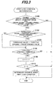
- FIG. 2 is a flowchart showing the determination operation.
- the illustrated program is executed by the ECU 84 at predetermined interval, e.g., 10 milliseconds.
- the program starts at S10, in which a first load condition determination process is conducted.
- FIG. 3 is a subroutine flowchart showing the process.
- the desired engine speed is a speed determined in accordance with the load 36, i.e., a type or nature of the load 36.
- the constant value is set to a small value of, e.g., 100 to 200 rpm.
- the processing of S100 is done for determining whether the engine 10 is stably rotated in a normal speed range which is determined depending on the type of the load 36.
- a threshold value is greater than a value (opening) obtained by adding a predetermined value to the detected throttle opening.
- the initial threshold value is set to an appropriate value and the predetermined value is a value corresponding to throttle opening of 3 degrees or thereabout.
- the program then proceeds to S106, in which it is determined whether the detected throttle opening is greater than the threshold value changed (set) in S104. When the result is negative, the remaining steps are skipped. If the program proceeded to S104, the result in S106 is naturally negative.
- the program then proceeds to S 110, in which it is determined whether the counter value C is greater than a prescribed value n (e.g., 50). Since this subroutine flowchart of FIG. 3 is executed at predetermined intervals, the processing of S110 amounts to determining whether a predetermined time period (e.g., 0.5 second) corresponding to the prescribed value n has elapsed.
- a predetermined time period e.g., 0.5 second
- the program proceeds to S12, in which it is determined whether the engine 10 is under first load condition.
- S12 the program in the FIG. 3 subroutine flowchart has not proceeded to S 112
- the result in S12 is negative and the program proceeds to S14, in which a second load condition determination process is conducted.
- FIG. 4 is a subroutine flowchart showing the process.
- a differential value (a change amount per a unit time) dTH of the throttle opening is calculated. Specifically, a preceding value of the throttle opening is stored in memory and a difference between the current and preceding values is calculated as the differential value dTH.
- the program then proceeds to S202, in which a differential value (a change amount per the unit time) dNE of the engine speed is calculated. Similarly, a preceding value of the engine speed is stored in memory and a difference between the current and preceding values is calculated as the differential value dNE.
- the program then proceeds to S204, in which a parameter A is calculated.
- the parameter A is calculated by multiplying the engine speed differential value dNE by a gain K and by subtracting an absolute value of the product from an absolute value of the throttle opening differential value dTH.
- the gain K is an appropriate small value, e.g., 0.001.
- the program next proceeds to S206, in which a parameter B indicating a moving average of n number of parameters A is calculated.
- the number n is set to an appropriate value, e.g., 16.
- the program then proceeds to S208, in which the parameter B is compared to a second threshold value.
- the parameter B exceeds the second threshold value, the result is affirmative and the program proceeds to S210, in which it is determined that the engine 10 is under load condition (more precisely under second load condition), and the bit of a control flag is set to 1.
- S210 in which it is determined that the engine 10 is under load condition (more precisely under second load condition), and the bit of a control flag is set to 1.
- this subroutine program is terminated.
- the reason why the parameter B comprising the moving average of n number of parameters A is used for comparison to the second threshold value in S208 is also to avoid misjudgment due to temporal noise of detected throttle opening and engine speed.
- the embodiment is configured to have an apparatus for and a method of detecting condition of load connected to a general-purpose internal combustion engine (10) equipped with an electronic governor (90) having an actuator (electric throttle motor 72) that moves a throttle value (68) installed in an air intake passage (62) to regulate a speed of the engine, comprising: a throttle opening detector (throttle opening sensor 76, ECU 84) that detects an opening of the throttle valve; an engine speed detector (power coil 44, ECU 84) that detects the engine speed; a desired engine speed convergence determiner (ECU 84, S10, S100) that determines whether the detected engine speed converges to a desired engine speed; a threshold value changer (ECU 84, S10, S 102, S104) that compares a first threshold value with a sum obtained by adding a predetermined value to the detected throttle opening and changes the threshold value to the sum if the first threshold value is less than the sum, when it is determined that the detected engine speed converges to the desired engine speed; a first throttle opening detector
- a condition of the load can be accurately determined. Specifically, since the throttle opening when the engine is stably operated in the normal speed range is detected or specified and the threshold value is newly set with a value obtained by adding the predetermined value to the specified throttle opening, the threshold value can be appropriately set, thereby enabling to accurately determine whether the engine 10 is under the load condition.
- the second load condition determination is adapted to compare the parameter A obtained by subtracting the engine speed differential value dNE from the throttle opening differential value dTH (more exactly, the parameter B indicating the moving average of n number of parameters A) to the second threshold value, and determine that it is in the load condition when the parameter exceeds the second threshold value. With this, a condition of the load can be further accurately determined.
- the desired engine speed changer (ECU 84, S18, S20) changes the desired engine speed in response to results of determination of the first load condition determiner and the second load condition determiner, it becomes possible to operate the engine 10 more appropriately.
- the desired engine speed changer changes the desired engine speed to a normal engine speed determined by nature of the load when the engine is determined to be under the first load condition and the second load condition (S20).
- the desired engine speed changer changes the desired engine speed to an idling speed when the engine is determined to be neither under the first load condition nor under the second load condition (S 18).
- the apparatus and method further includes: a counter (S106, S108) that counts a number of times that the throttle opening exceeds the first threshold value; and the first load condition determiner determines that the engine is under the first load condition when the counted number of times (C) exceeds a prescribed value (n) (S112).
- the warning lamp 84a may be lit instead to inform the operator. Any other audible or visible device can also be applied.
- a first threshold value is compared with a sum obtained by adding a predetermined value to a detected throttle opening and changes the threshold value to the sum if the first threshold value is less than the sum and the engine is determined to be under first load condition if the throttle opening exceeds the threshold value S10 .
- a second threshold value is compared with a difference obtained by subtracting change amounts of the engine speed and throttle opening and the engine is determined to be under second load condition if the difference exceeds the second threshold value S14 , thereby enabling to accurately detect a condition of a load connected to the engine.
- the desired engine speed is changed in response to results of the determinations S 18, S20 .
Landscapes
- Engineering & Computer Science (AREA)
- Chemical & Material Sciences (AREA)
- Combustion & Propulsion (AREA)
- Mechanical Engineering (AREA)
- General Engineering & Computer Science (AREA)
- Combined Controls Of Internal Combustion Engines (AREA)
- Electrical Control Of Air Or Fuel Supplied To Internal-Combustion Engine (AREA)
Claims (7)
- Appareil pour détecter une condition d'une charge pouvant être connectée à un moteur à combustion interne d'usage général (10) équipé d'un régulateur de vitesse électronique (90) comportant un actionneur (72) qui déplace un papillon des gaz (68) installé dans un passage d'admission d'air (62) pour réguler une vitesse du moteur,
caractérisé par :un détecteur d'ouverture de papillon (76, 84) qui détecte une ouverture du papillon des gaz ;un détecteur de vitesse de moteur (44, 84) qui détecte la vitesse du moteur ;un dispositif de détermination de convergence de vitesse de moteur souhaitée (84, S10, S100) qui détermine si la vitesse de moteur détectée converge vers une vitesse de moteur souhaitée ;un dispositif de changement de valeur de seuil (84, S10, S102, S104) qui compare une première valeur de seuil avec une somme obtenue en ajoutant une valeur prédéterminée à l'ouverture de papillon détectée et change la valeur de seuil en la somme si la première valeur de seuil est inférieure à la somme, lorsqu'il est déterminé que la vitesse de moteur détectée converge vers la vitesse de moteur souhaitée ;un premier dispositif de détermination de condition de charge (84, S10, S106 à S112) qui détermine que le moteur est dans une première condition de charge où la charge consomme la puissance générée par le moteur lorsque l'ouverture de papillon dépasse la première valeur de seuil ;un deuxième dispositif de détermination de condition de charge (84, S14, S200 à S210) qui compare une deuxième valeur de seuil avec une différence obtenue en multipliant une quantité de changement de la vitesse de moteur par temps unitaire par un gain (K) et en soustrayant le produit d'une quantité de changement de l'ouverture de papillon par temps unitaire, et détermine que le moteur est dans une deuxième condition de charge où la charge consomme la puissance générée par le moteur lorsque la différence dépasse la deuxième valeur de seuil ; etun dispositif de changement de vitesse de moteur souhaitée (84, S18, S20) qui change la vitesse de moteur souhaitée en réponse aux résultats de détermination du premier dispositif de détermination de condition de charge et du deuxième dispositif de détermination de condition de charge. - Appareil selon la revendication 1, dans lequel le dispositif de changement de vitesse de moteur souhaitée change la vitesse de moteur souhaitée en une vitesse de moteur normale déterminée par la nature de la charge lorsqu'il est déterminé que le moteur est dans la première condition de charge et la deuxième condition de charge (S20).
- Appareil selon la revendication 1 ou 2, dans lequel le dispositif de changement de vitesse de moteur souhaitée change la vitesse de moteur souhaitée en une vitesse de ralenti lorsqu'il est déterminé que le moteur n'est ni dans la première condition de charge ni dans la deuxième condition de charge (S18).
- Appareil selon l'une quelconque des revendications 1 à 3, comprenant en outré :un compteur (S106, S108) qui compte un nombre de fois que l'ouverture de papillon dépasse la première valeur de seuil ;et le premier dispositif de détermination de condition de charge détermine que le moteur est dans la première condition de charge lorsque le nombre de fois compté (C) dépasse une valeur prescrite (n) (S112).
- Procédé de détection de la condition d'une charge pouvant être connectée à un moteur à combustion interne d'usage général (10) équipé d'un régulateur de vitesse électronique (90) comportant un actionneur (72) qui déplace un papillon des gaz (68) installé dans un passage d'admission d'air (62) pour réguler une vitesse du moteur,
caractérisé par les étapes consistant à :détecter une ouverture du papillon des gaz ;détecter la vitesse du moteur ;déterminer si la vitesse de moteur détectée converge vers une vitesse de moteur souhaitée (84, S10, S100) ;comparer une première valeur de seuil avec une somme obtenue en ajoutant une valeur prédéterminée à l'ouverture de papillon détectée et changer la valeur de seuil en la somme si la première valeur de seuil est inférieure à la somme, lorsqu'il est déterminé que la vitesse de moteur détectée converge vers la vitesse de moteur souhaitée (84, S10, S102, S104) ;compter un nombre de fois que l'ouverture de papillon dépasse la première valeur de seuil (84, S10, S102, S104) ;déterminer que le moteur est dans une première condition de charge lorsque la charge consomme la puissance générée par le moteur lorsque le nombre de fois compté dépasse une valeur prescrite (84, S10, S110, S112) ;comparer une deuxième valeur de seuil avec une différence obtenue en multipliant une quantité de changement de la vitesse de moteur par temps unitaire par un gain (K) et en soustrayant le produit d'une quantité de changement de l'ouverture de papillon par temps unitaire, et déterminer que le moteur est dans une deuxième condition de charge où la charge consomme la puissance générée par le moteur lorsque la différence dépasse la deuxième valeur de seuil (84, S14, S200 à S210) ; etchanger la vitesse de moteur souhaitée en réponse aux résultats de détermination du premier dispositif de détermination de condition de charge et du deuxième dispositif de détermination de condition de charge (84, S18, S20) . - Procédé selon la revendication 5, dans lequel l'étape de changement de vitesse de moteur souhaitée change la vitesse de moteur souhaitée en une vitesse de moteur normale déterminée par la nature de la charge lorsqu'il est déterminé que le moteur est dans la première condition de charge et la deuxième condition de charge (S20).
- Procédé selon la revendication 5 ou 6, dans lequel le dispositif de changement de vitesse de moteur souhaitée change la vitesse de moteur souhaitée en une vitesse de ralenti lorsqu'il est déterminé que le moteur n'est ni dans la première condition de charge ni dans la deuxième condition de charge (S18).
Applications Claiming Priority (1)
| Application Number | Priority Date | Filing Date | Title |
|---|---|---|---|
| JP2009107979 | 2009-04-27 |
Publications (2)
| Publication Number | Publication Date |
|---|---|
| EP2246548A1 EP2246548A1 (fr) | 2010-11-03 |
| EP2246548B1 true EP2246548B1 (fr) | 2012-07-11 |
Family
ID=42313427
Family Applications (1)
| Application Number | Title | Priority Date | Filing Date |
|---|---|---|---|
| EP10160853A Active EP2246548B1 (fr) | 2009-04-27 | 2010-04-23 | Appareil de détection de condition de charge pour moteur polyvalent |
Country Status (4)
| Country | Link |
|---|---|
| US (1) | US8347858B2 (fr) |
| EP (1) | EP2246548B1 (fr) |
| JP (1) | JP5329473B2 (fr) |
| CN (1) | CN101871398B (fr) |
Families Citing this family (5)
| Publication number | Priority date | Publication date | Assignee | Title |
|---|---|---|---|---|
| US9823715B1 (en) * | 2007-06-14 | 2017-11-21 | Switch, Ltd. | Data center air handling unit including uninterruptable cooling fan with weighted rotor and method of using the same |
| US11452242B2 (en) | 2007-06-14 | 2022-09-20 | Switch, Ltd. | Air handling unit with a canopy thereover for use with a data center and method of using the same |
| JP2013194578A (ja) * | 2012-03-19 | 2013-09-30 | Honda Motor Co Ltd | 流体ポンプの制御装置 |
| AU2015252884A1 (en) | 2014-05-01 | 2016-11-17 | Briggs & Stratton Corporation | Electronic governor system and load sensing system |
| WO2021176335A1 (fr) | 2020-03-02 | 2021-09-10 | Briggs & Stratton, Llc | Moteur à combustion interne à entretien d'huile réduit |
Family Cites Families (14)
| Publication number | Priority date | Publication date | Assignee | Title |
|---|---|---|---|---|
| JPS61171856A (ja) * | 1985-01-24 | 1986-08-02 | Daihatsu Motor Co Ltd | エンジンのアイドル回転数制御装置 |
| DE4203247C2 (de) * | 1991-02-18 | 1998-02-26 | Mitsubishi Electric Corp | Fehlzündungsüberwachungsvorrichtung für eine Brennkraftmaschine |
| JP3610687B2 (ja) * | 1995-12-12 | 2005-01-19 | トヨタ自動車株式会社 | 内燃機関の始動制御装置およびその制御方法 |
| JP4504604B2 (ja) * | 2001-09-20 | 2010-07-14 | 本田技研工業株式会社 | 汎用エンジンの制御装置 |
| US7200486B2 (en) * | 2001-10-15 | 2007-04-03 | Toyota Jidosha Kabushiki Kaisha | Apparatus for estimating quantity of intake air for internal combustion engine |
| JP3984847B2 (ja) | 2002-03-26 | 2007-10-03 | 株式会社クボタ | エンジンの燃料供給装置 |
| JP4146306B2 (ja) * | 2003-07-28 | 2008-09-10 | トヨタ自動車株式会社 | 自動変速機の変速制御装置 |
| JP2005076522A (ja) * | 2003-08-29 | 2005-03-24 | Honda Motor Co Ltd | 汎用エンジンのスロットル装置 |
| US6901324B2 (en) * | 2003-09-30 | 2005-05-31 | Caterpillar Inc | System and method for predictive load management |
| DE102004010519B4 (de) * | 2004-03-04 | 2007-10-04 | Mehnert, Jens, Dr. Ing. | Verfahren zum Steuern des Luftmengenstromes von Verbrennungskraftmaschinen |
| JP2005299519A (ja) | 2004-04-12 | 2005-10-27 | Honda Motor Co Ltd | 高圧洗浄機のエンジン回転数制御装置 |
| JP2006170037A (ja) * | 2004-12-15 | 2006-06-29 | Honda Motor Co Ltd | コンクリートカッタの制御装置 |
| JP4399387B2 (ja) * | 2005-03-28 | 2010-01-13 | 日立オートモティブシステムズ株式会社 | 可変動弁機構の制御装置 |
| JP4673823B2 (ja) * | 2006-01-26 | 2011-04-20 | 本田技研工業株式会社 | エンジン駆動式作業機 |
-
2010
- 2010-04-20 US US12/763,759 patent/US8347858B2/en active Active
- 2010-04-21 JP JP2010097562A patent/JP5329473B2/ja not_active Expired - Fee Related
- 2010-04-23 EP EP10160853A patent/EP2246548B1/fr active Active
- 2010-04-26 CN CN201010167764.1A patent/CN101871398B/zh not_active Expired - Fee Related
Also Published As
| Publication number | Publication date |
|---|---|
| US20100269786A1 (en) | 2010-10-28 |
| CN101871398A (zh) | 2010-10-27 |
| US8347858B2 (en) | 2013-01-08 |
| JP2010276017A (ja) | 2010-12-09 |
| JP5329473B2 (ja) | 2013-10-30 |
| EP2246548A1 (fr) | 2010-11-03 |
| CN101871398B (zh) | 2013-04-10 |
Similar Documents
| Publication | Publication Date | Title |
|---|---|---|
| EP2246547B1 (fr) | Appareil de commande pour moteur polyvalent | |
| KR101113391B1 (ko) | 범용 내연 기관의 점화 제어 장치 | |
| EP2246548B1 (fr) | Appareil de détection de condition de charge pour moteur polyvalent | |
| US8327825B2 (en) | Control apparatus for internal combustion engine | |
| US8770172B2 (en) | Fuel shortage detecting apparatus for general-purpose engine | |
| JP5022333B2 (ja) | 汎用内燃機関の無負荷検出方法および装置 | |
| JP5369070B2 (ja) | 汎用エンジンの燃料切れ判定装置 | |
| US7328100B2 (en) | Coil failure detection system for general-purpose engine | |
| US7826955B2 (en) | General-purpose internal combustion engine | |
| JP5986063B2 (ja) | 汎用エンジンの点火制御装置 | |
| JP4434672B2 (ja) | エンジン発電機 | |
| JP5357120B2 (ja) | 汎用エンジンの燃料切れ判定装置 | |
| JP2005090343A (ja) | エンジン発電機 | |
| JP2012057534A (ja) | 汎用エンジンの制御装置 | |
| JP2005076523A (ja) | 汎用エンジンの過出力警告装置 |
Legal Events
| Date | Code | Title | Description |
|---|---|---|---|
| PUAI | Public reference made under article 153(3) epc to a published international application that has entered the european phase |
Free format text: ORIGINAL CODE: 0009012 |
|
| 17P | Request for examination filed |
Effective date: 20100423 |
|
| AK | Designated contracting states |
Kind code of ref document: A1 Designated state(s): AT BE BG CH CY CZ DE DK EE ES FI FR GB GR HR HU IE IS IT LI LT LU LV MC MK MT NL NO PL PT RO SE SI SK SM TR |
|
| AX | Request for extension of the european patent |
Extension state: AL BA ME RS |
|
| GRAP | Despatch of communication of intention to grant a patent |
Free format text: ORIGINAL CODE: EPIDOSNIGR1 |
|
| GRAS | Grant fee paid |
Free format text: ORIGINAL CODE: EPIDOSNIGR3 |
|
| GRAA | (expected) grant |
Free format text: ORIGINAL CODE: 0009210 |
|
| AK | Designated contracting states |
Kind code of ref document: B1 Designated state(s): AT BE BG CH CY CZ DE DK EE ES FI FR GB GR HR HU IE IS IT LI LT LU LV MC MK MT NL NO PL PT RO SE SI SK SM TR |
|
| REG | Reference to a national code |
Ref country code: GB Ref legal event code: FG4D |
|
| REG | Reference to a national code |
Ref country code: CH Ref legal event code: EP |
|
| REG | Reference to a national code |
Ref country code: AT Ref legal event code: REF Ref document number: 566266 Country of ref document: AT Kind code of ref document: T Effective date: 20120715 |
|
| REG | Reference to a national code |
Ref country code: IE Ref legal event code: FG4D |
|
| REG | Reference to a national code |
Ref country code: DE Ref legal event code: R096 Ref document number: 602010002141 Country of ref document: DE Effective date: 20120906 |
|
| REG | Reference to a national code |
Ref country code: NL Ref legal event code: VDEP Effective date: 20120711 |
|
| REG | Reference to a national code |
Ref country code: AT Ref legal event code: MK05 Ref document number: 566266 Country of ref document: AT Kind code of ref document: T Effective date: 20120711 |
|
| REG | Reference to a national code |
Ref country code: LT Ref legal event code: MG4D Effective date: 20120711 |
|
| PG25 | Lapsed in a contracting state [announced via postgrant information from national office to epo] |
Ref country code: HR Free format text: LAPSE BECAUSE OF FAILURE TO SUBMIT A TRANSLATION OF THE DESCRIPTION OR TO PAY THE FEE WITHIN THE PRESCRIBED TIME-LIMIT Effective date: 20120711 Ref country code: LT Free format text: LAPSE BECAUSE OF FAILURE TO SUBMIT A TRANSLATION OF THE DESCRIPTION OR TO PAY THE FEE WITHIN THE PRESCRIBED TIME-LIMIT Effective date: 20120711 Ref country code: CY Free format text: LAPSE BECAUSE OF FAILURE TO SUBMIT A TRANSLATION OF THE DESCRIPTION OR TO PAY THE FEE WITHIN THE PRESCRIBED TIME-LIMIT Effective date: 20120711 Ref country code: NO Free format text: LAPSE BECAUSE OF FAILURE TO SUBMIT A TRANSLATION OF THE DESCRIPTION OR TO PAY THE FEE WITHIN THE PRESCRIBED TIME-LIMIT Effective date: 20121011 Ref country code: AT Free format text: LAPSE BECAUSE OF FAILURE TO SUBMIT A TRANSLATION OF THE DESCRIPTION OR TO PAY THE FEE WITHIN THE PRESCRIBED TIME-LIMIT Effective date: 20120711 Ref country code: FI Free format text: LAPSE BECAUSE OF FAILURE TO SUBMIT A TRANSLATION OF THE DESCRIPTION OR TO PAY THE FEE WITHIN THE PRESCRIBED TIME-LIMIT Effective date: 20120711 Ref country code: IS Free format text: LAPSE BECAUSE OF FAILURE TO SUBMIT A TRANSLATION OF THE DESCRIPTION OR TO PAY THE FEE WITHIN THE PRESCRIBED TIME-LIMIT Effective date: 20121111 Ref country code: BE Free format text: LAPSE BECAUSE OF FAILURE TO SUBMIT A TRANSLATION OF THE DESCRIPTION OR TO PAY THE FEE WITHIN THE PRESCRIBED TIME-LIMIT Effective date: 20120711 |
|
| PG25 | Lapsed in a contracting state [announced via postgrant information from national office to epo] |
Ref country code: GR Free format text: LAPSE BECAUSE OF FAILURE TO SUBMIT A TRANSLATION OF THE DESCRIPTION OR TO PAY THE FEE WITHIN THE PRESCRIBED TIME-LIMIT Effective date: 20121012 Ref country code: PT Free format text: LAPSE BECAUSE OF FAILURE TO SUBMIT A TRANSLATION OF THE DESCRIPTION OR TO PAY THE FEE WITHIN THE PRESCRIBED TIME-LIMIT Effective date: 20121112 Ref country code: LV Free format text: LAPSE BECAUSE OF FAILURE TO SUBMIT A TRANSLATION OF THE DESCRIPTION OR TO PAY THE FEE WITHIN THE PRESCRIBED TIME-LIMIT Effective date: 20120711 Ref country code: PL Free format text: LAPSE BECAUSE OF FAILURE TO SUBMIT A TRANSLATION OF THE DESCRIPTION OR TO PAY THE FEE WITHIN THE PRESCRIBED TIME-LIMIT Effective date: 20120711 Ref country code: SE Free format text: LAPSE BECAUSE OF FAILURE TO SUBMIT A TRANSLATION OF THE DESCRIPTION OR TO PAY THE FEE WITHIN THE PRESCRIBED TIME-LIMIT Effective date: 20120711 Ref country code: SI Free format text: LAPSE BECAUSE OF FAILURE TO SUBMIT A TRANSLATION OF THE DESCRIPTION OR TO PAY THE FEE WITHIN THE PRESCRIBED TIME-LIMIT Effective date: 20120711 |
|
| PG25 | Lapsed in a contracting state [announced via postgrant information from national office to epo] |
Ref country code: NL Free format text: LAPSE BECAUSE OF FAILURE TO SUBMIT A TRANSLATION OF THE DESCRIPTION OR TO PAY THE FEE WITHIN THE PRESCRIBED TIME-LIMIT Effective date: 20120711 |
|
| PG25 | Lapsed in a contracting state [announced via postgrant information from national office to epo] |
Ref country code: EE Free format text: LAPSE BECAUSE OF FAILURE TO SUBMIT A TRANSLATION OF THE DESCRIPTION OR TO PAY THE FEE WITHIN THE PRESCRIBED TIME-LIMIT Effective date: 20120711 Ref country code: CZ Free format text: LAPSE BECAUSE OF FAILURE TO SUBMIT A TRANSLATION OF THE DESCRIPTION OR TO PAY THE FEE WITHIN THE PRESCRIBED TIME-LIMIT Effective date: 20120711 Ref country code: ES Free format text: LAPSE BECAUSE OF FAILURE TO SUBMIT A TRANSLATION OF THE DESCRIPTION OR TO PAY THE FEE WITHIN THE PRESCRIBED TIME-LIMIT Effective date: 20121022 Ref country code: RO Free format text: LAPSE BECAUSE OF FAILURE TO SUBMIT A TRANSLATION OF THE DESCRIPTION OR TO PAY THE FEE WITHIN THE PRESCRIBED TIME-LIMIT Effective date: 20120711 Ref country code: DK Free format text: LAPSE BECAUSE OF FAILURE TO SUBMIT A TRANSLATION OF THE DESCRIPTION OR TO PAY THE FEE WITHIN THE PRESCRIBED TIME-LIMIT Effective date: 20120711 |
|
| PLBE | No opposition filed within time limit |
Free format text: ORIGINAL CODE: 0009261 |
|
| STAA | Information on the status of an ep patent application or granted ep patent |
Free format text: STATUS: NO OPPOSITION FILED WITHIN TIME LIMIT |
|
| PG25 | Lapsed in a contracting state [announced via postgrant information from national office to epo] |
Ref country code: SK Free format text: LAPSE BECAUSE OF FAILURE TO SUBMIT A TRANSLATION OF THE DESCRIPTION OR TO PAY THE FEE WITHIN THE PRESCRIBED TIME-LIMIT Effective date: 20120711 Ref country code: IT Free format text: LAPSE BECAUSE OF FAILURE TO SUBMIT A TRANSLATION OF THE DESCRIPTION OR TO PAY THE FEE WITHIN THE PRESCRIBED TIME-LIMIT Effective date: 20120711 |
|
| 26N | No opposition filed |
Effective date: 20130412 |
|
| PG25 | Lapsed in a contracting state [announced via postgrant information from national office to epo] |
Ref country code: BG Free format text: LAPSE BECAUSE OF FAILURE TO SUBMIT A TRANSLATION OF THE DESCRIPTION OR TO PAY THE FEE WITHIN THE PRESCRIBED TIME-LIMIT Effective date: 20121011 |
|
| REG | Reference to a national code |
Ref country code: DE Ref legal event code: R097 Ref document number: 602010002141 Country of ref document: DE Effective date: 20130412 |
|
| PG25 | Lapsed in a contracting state [announced via postgrant information from national office to epo] |
Ref country code: MC Free format text: LAPSE BECAUSE OF FAILURE TO SUBMIT A TRANSLATION OF THE DESCRIPTION OR TO PAY THE FEE WITHIN THE PRESCRIBED TIME-LIMIT Effective date: 20120711 |
|
| REG | Reference to a national code |
Ref country code: IE Ref legal event code: MM4A |
|
| PG25 | Lapsed in a contracting state [announced via postgrant information from national office to epo] |
Ref country code: IE Free format text: LAPSE BECAUSE OF NON-PAYMENT OF DUE FEES Effective date: 20130423 |
|
| REG | Reference to a national code |
Ref country code: CH Ref legal event code: PL |
|
| PG25 | Lapsed in a contracting state [announced via postgrant information from national office to epo] |
Ref country code: LI Free format text: LAPSE BECAUSE OF NON-PAYMENT OF DUE FEES Effective date: 20140430 Ref country code: CH Free format text: LAPSE BECAUSE OF NON-PAYMENT OF DUE FEES Effective date: 20140430 |
|
| PG25 | Lapsed in a contracting state [announced via postgrant information from national office to epo] |
Ref country code: MT Free format text: LAPSE BECAUSE OF FAILURE TO SUBMIT A TRANSLATION OF THE DESCRIPTION OR TO PAY THE FEE WITHIN THE PRESCRIBED TIME-LIMIT Effective date: 20120711 |
|
| PG25 | Lapsed in a contracting state [announced via postgrant information from national office to epo] |
Ref country code: SM Free format text: LAPSE BECAUSE OF FAILURE TO SUBMIT A TRANSLATION OF THE DESCRIPTION OR TO PAY THE FEE WITHIN THE PRESCRIBED TIME-LIMIT Effective date: 20120711 |
|
| PG25 | Lapsed in a contracting state [announced via postgrant information from national office to epo] |
Ref country code: TR Free format text: LAPSE BECAUSE OF FAILURE TO SUBMIT A TRANSLATION OF THE DESCRIPTION OR TO PAY THE FEE WITHIN THE PRESCRIBED TIME-LIMIT Effective date: 20120711 |
|
| PG25 | Lapsed in a contracting state [announced via postgrant information from national office to epo] |
Ref country code: HU Free format text: LAPSE BECAUSE OF FAILURE TO SUBMIT A TRANSLATION OF THE DESCRIPTION OR TO PAY THE FEE WITHIN THE PRESCRIBED TIME-LIMIT; INVALID AB INITIO Effective date: 20100423 Ref country code: MK Free format text: LAPSE BECAUSE OF FAILURE TO SUBMIT A TRANSLATION OF THE DESCRIPTION OR TO PAY THE FEE WITHIN THE PRESCRIBED TIME-LIMIT Effective date: 20120711 Ref country code: LU Free format text: LAPSE BECAUSE OF NON-PAYMENT OF DUE FEES Effective date: 20130423 |
|
| REG | Reference to a national code |
Ref country code: FR Ref legal event code: PLFP Year of fee payment: 7 |
|
| REG | Reference to a national code |
Ref country code: FR Ref legal event code: PLFP Year of fee payment: 8 |
|
| REG | Reference to a national code |
Ref country code: FR Ref legal event code: PLFP Year of fee payment: 9 |
|
| REG | Reference to a national code |
Ref country code: DE Ref legal event code: R084 Ref document number: 602010002141 Country of ref document: DE |
|
| REG | Reference to a national code |
Ref country code: GB Ref legal event code: 746 Effective date: 20191219 |
|
| PGFP | Annual fee paid to national office [announced via postgrant information from national office to epo] |
Ref country code: FR Payment date: 20210310 Year of fee payment: 12 |
|
| PGFP | Annual fee paid to national office [announced via postgrant information from national office to epo] |
Ref country code: GB Payment date: 20210331 Year of fee payment: 12 |
|
| GBPC | Gb: european patent ceased through non-payment of renewal fee |
Effective date: 20220423 |
|
| PG25 | Lapsed in a contracting state [announced via postgrant information from national office to epo] |
Ref country code: GB Free format text: LAPSE BECAUSE OF NON-PAYMENT OF DUE FEES Effective date: 20220423 Ref country code: FR Free format text: LAPSE BECAUSE OF NON-PAYMENT OF DUE FEES Effective date: 20220430 |
|
| PGFP | Annual fee paid to national office [announced via postgrant information from national office to epo] |
Ref country code: DE Payment date: 20250319 Year of fee payment: 16 |