EP2246558A2 - Pale d'éolienne avec segments du bord d'attaque préfabriqués - Google Patents
Pale d'éolienne avec segments du bord d'attaque préfabriqués Download PDFInfo
- Publication number
- EP2246558A2 EP2246558A2 EP20100161199 EP10161199A EP2246558A2 EP 2246558 A2 EP2246558 A2 EP 2246558A2 EP 20100161199 EP20100161199 EP 20100161199 EP 10161199 A EP10161199 A EP 10161199A EP 2246558 A2 EP2246558 A2 EP 2246558A2
- Authority
- EP
- European Patent Office
- Prior art keywords
- leading edge
- blade
- wind turbine
- shell
- segment
- Prior art date
- Legal status (The legal status is an assumption and is not a legal conclusion. Google has not performed a legal analysis and makes no representation as to the accuracy of the status listed.)
- Granted
Links
Images


Classifications
-
- F—MECHANICAL ENGINEERING; LIGHTING; HEATING; WEAPONS; BLASTING
- F03—MACHINES OR ENGINES FOR LIQUIDS; WIND, SPRING, OR WEIGHT MOTORS; PRODUCING MECHANICAL POWER OR A REACTIVE PROPULSIVE THRUST, NOT OTHERWISE PROVIDED FOR
- F03D—WIND MOTORS
- F03D1/00—Wind motors with rotation axis substantially parallel to the air flow entering the rotor
- F03D1/06—Rotors
- F03D1/065—Rotors characterised by their construction elements
- F03D1/0675—Rotors characterised by their construction elements of the blades
-
- F—MECHANICAL ENGINEERING; LIGHTING; HEATING; WEAPONS; BLASTING
- F03—MACHINES OR ENGINES FOR LIQUIDS; WIND, SPRING, OR WEIGHT MOTORS; PRODUCING MECHANICAL POWER OR A REACTIVE PROPULSIVE THRUST, NOT OTHERWISE PROVIDED FOR
- F03D—WIND MOTORS
- F03D80/00—Details, components or accessories not provided for in groups F03D1/00 - F03D17/00
- F03D80/30—Lightning protection
-
- F—MECHANICAL ENGINEERING; LIGHTING; HEATING; WEAPONS; BLASTING
- F05—INDEXING SCHEMES RELATING TO ENGINES OR PUMPS IN VARIOUS SUBCLASSES OF CLASSES F01-F04
- F05B—INDEXING SCHEME RELATING TO WIND, SPRING, WEIGHT, INERTIA OR LIKE MOTORS, TO MACHINES OR ENGINES FOR LIQUIDS COVERED BY SUBCLASSES F03B, F03D AND F03G
- F05B2230/00—Manufacture
- F05B2230/50—Building or constructing in particular ways
-
- F—MECHANICAL ENGINEERING; LIGHTING; HEATING; WEAPONS; BLASTING
- F05—INDEXING SCHEMES RELATING TO ENGINES OR PUMPS IN VARIOUS SUBCLASSES OF CLASSES F01-F04
- F05B—INDEXING SCHEME RELATING TO WIND, SPRING, WEIGHT, INERTIA OR LIKE MOTORS, TO MACHINES OR ENGINES FOR LIQUIDS COVERED BY SUBCLASSES F03B, F03D AND F03G
- F05B2230/00—Manufacture
- F05B2230/60—Assembly methods
-
- Y—GENERAL TAGGING OF NEW TECHNOLOGICAL DEVELOPMENTS; GENERAL TAGGING OF CROSS-SECTIONAL TECHNOLOGIES SPANNING OVER SEVERAL SECTIONS OF THE IPC; TECHNICAL SUBJECTS COVERED BY FORMER USPC CROSS-REFERENCE ART COLLECTIONS [XRACs] AND DIGESTS
- Y02—TECHNOLOGIES OR APPLICATIONS FOR MITIGATION OR ADAPTATION AGAINST CLIMATE CHANGE
- Y02E—REDUCTION OF GREENHOUSE GAS [GHG] EMISSIONS, RELATED TO ENERGY GENERATION, TRANSMISSION OR DISTRIBUTION
- Y02E10/00—Energy generation through renewable energy sources
- Y02E10/70—Wind energy
- Y02E10/72—Wind turbines with rotation axis in wind direction
-
- Y—GENERAL TAGGING OF NEW TECHNOLOGICAL DEVELOPMENTS; GENERAL TAGGING OF CROSS-SECTIONAL TECHNOLOGIES SPANNING OVER SEVERAL SECTIONS OF THE IPC; TECHNICAL SUBJECTS COVERED BY FORMER USPC CROSS-REFERENCE ART COLLECTIONS [XRACs] AND DIGESTS
- Y02—TECHNOLOGIES OR APPLICATIONS FOR MITIGATION OR ADAPTATION AGAINST CLIMATE CHANGE
- Y02P—CLIMATE CHANGE MITIGATION TECHNOLOGIES IN THE PRODUCTION OR PROCESSING OF GOODS
- Y02P70/00—Climate change mitigation technologies in the production process for final industrial or consumer products
- Y02P70/50—Manufacturing or production processes characterised by the final manufactured product
Definitions
- the present invention relates generally to wind turbine rotor blades, and more particularly to a wind turbine rotor blade having one or more prefabricated leading edge components.
- a modem wind turbine typically includes a tower, generator, gearbox, nacelle, and one more rotor blades.
- the rotor blades capture kinetic energy from wind using known foil principles, and transmit the kinetic energy through rotational energy to turn a shaft coupling the rotor blades to a gearbox, or if a gearbox is not used, directly to the generator.
- the generator then converts the mechanical energy to electrical energy that may be deployed to a utility grid.
- the construction of a modem wind turbine rotor blade generally includes upper and lower shell components bonded at a leading and trailing edge of the blade, spar caps, and one or more shear webs.
- the skin typically manufactured from layers of fiber composite and a lightweight core material, forms the exterior aerodynamic foil shape of the rotor blade.
- the spar caps provide increased rotor blade strength by integrating one or more structural elements running along the length of the rotor blade on both interior sides of the rotor blade.
- Shear webs are structural beam-like components running essentially perpendicular between the top and bottom spar caps and extending across the interior portion of the rotor blade between the outer skins.
- Spar caps have typically been constructed from glass fiber reinforced composites, though some larger blades are beginning to include spar caps constructed from carbon fiber reinforced composites.
- the leading edge of the wind turbine blade is an area of concern.
- the bonding of the shell components at the leading edge is difficult to control. Overbite or underbite between the shell components can occur, often causing extensive rework of the blade.
- the thickness of the bond can vary from blade to blade, and can often drift outside of a design tolerance.
- the leading edge bond between the shell components can result in a blade where the most dimensional uncertainty is at a very critical aerodynamic location on the blade.
- the leading edge of the turbine blade is highly susceptible to erosion and weathering, and can be damaged during transportation and erection of the wind turbine. These conditions lead to costly on-site repairs.
- Various aspects of the present invention provide for a wind turbine rotor blade that incorporates one or more prefabricated leading edge segments. These segments can be manufactured with precisely controlled geometries, and do not include a leading edge bond.
- the blades provide a solution to several of the problems associated with conventional blades having shell components bonded together at the leading edge of the blade. Additional aspects and advantages of the invention are set forth in part in the following description, or may be obvious from the description, or may be learned through practice of the invention.
- a wind turbine rotor blade having a first shell component and a second shell component.
- the shell components are joined together at the trailing edge of the blade.
- Each of the shell components further includes a forward edge.
- At least one, and in a particular embodiment, a plurality of leading edge segments are joined to the shell components and aligned along the longitudinal length of the blade so as to define a continuous leading edge of the blade.
- the leading edge segments have an open-ended cross-sectional profile defined by an arcuate skin with first and second longitudinal edges and first and second end faces.
- the longitudinal edges of the leading edge segments are joined to the forward edge of the first shell component at a first bond line, and joined to the forward edge of the second shell component at a second bond line.
- the end faces of adjacent leading edge segments may be bonded together as well. With this construction, the leading edge portion of the blade between the first and second bond lines is a continuous unbroken surface defined by the aligned leading edge segments.
- the present invention also encompasses a kit for forming a wind turbine rotor blade from component parts.
- the kit may include a first shell component and a second shell component, with each of the shell components having a forward edge and a trailing edge.
- One or more leading edge segments are also provided, with each leading edge segment having an open-ended cross-sectional profile defined by an arcuate skin with first and second longitudinal edges and first and second end faces.
- the leading edge segments and the first and second shell components are configured relative to each other such that when assembled, the shell components define a bonded trailing edge of the blade, and the longitudinal edges of the leading edge segments are joined to the forward edge of the first shell component at a first bond line, and joined to the forward edge of the second shell component at a second bond line.
- the parts when assembled, define a blade with a leading edge that is a continuous unbroken surface defined by the skins of the aligned leading edge segments between the first and second bond lines.
- FIG. 1 is a schematic view of a conventional wind turbine 100.
- the wind turbine 100 includes a tower 110 with a machine nacelle 120 mounted at the top of the tower.
- a hub 130 having any number of rotor blades 140 is mounted to a lateral end of the machine nacelle 120.
- a typical configuration of a conventional rotor blade 140 includes a suction side shell component 142 and a pressure side shell component 144.
- the shell components 142, 144 are bonded together at a first bond 148 at the trailing edge 146 of the blade, and at a second bond 152 at the leading edge 150 of the blade.
- typically spar caps 160 are attached to the inside surface of the shell components 142, 144 along the length thereof, with a shear web 162 connected between the components.
- one or more additional braces 164 may be included for added support.
- the leading edge 150 is a critical aerodynamic section of the blade 140, and the presence of the leading edge bond 152 and conventional construction techniques can be problematic.
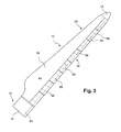
- FIGS. 3 and 4 are illustrations of embodiments of a wind turbine rotor blade 10 in accordance with aspects of the invention.
- the blade 10 includes a first shell component 18 and a second shell component 24 (FIG. 4A).
- the shell components 18, 24 may be individually formed, and may include inner and outer skins, and a core material sandwiched between the inner and outer skins.
- the inner and outer skins may be a fiber reinforced material, and the core material may be a lightweight material, such as balsa wood, extruded polystyrene foam, and the like, as is known in the art.
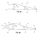
- the first shell component 18 includes a forward edge 20 ( FIG. 5A ), and the second shell component 24 includes a forward edge 26 ( FIG. 5A ).
- the shell components include respective trailing edges that are joined together at the trailing edge 33 of the blade 10. Typically, the trailing edges may be bonded at a bond point 30 ( FIG. 5A ) at the trailing edge 33.
- spar caps 48 may be attached to the inner skin surfaces of the respective shell components 18, 24, with a spar or shear web 50 connected between the spar caps 48.
- the spar caps 48 and web 50 provide structural support and rigidity to the blade 10.
- any manner of additional braces 52 may be included in construction of the blade 10, particularly for larger turbine blades. It should be appreciated that any manner of internal structural support configuration is within the scope and spirit of the invention.
- FIG. 3 illustrates an embodiment wherein a plurality of leading edge segments 34 are joined to the shell components 18, 24 and are aligned along a longitudinal length of the blade 10 so as to define a continuous leading edge 32 for the blade 10.
- FIG. 4 illustrates an alternate embodiment wherein a single edge segment 34 is joined to the shell components 18, 24 to define the continuous leading edge 32 for the blade 10. It should be appreciated that the invention encompasses any number of the leading edge segments 34, at that different economic, manufacturing, and structural considerations may apply to the different embodiments. For illustrative purposes, the embodiment of a blade 10 incorporating a plurality of the leading edge segments is described in greater detail herein.
- the leading edge segments 34 may complete the blade 10 from the tip 12 to the root 14 of the blade 10. In an alternative embodiment, fewer leading edge segments may be utilized, wherein a portion of the blade leading edge 32 is defined by the shell components 18, 24, or other structure.
- the leading edge segment 34 closest to the root 14 may also attach directly to a root ring 16, or other structure of the blade 10.
- the leading edge segment 34 closest to the tip 12 may attach to a tip component, which may be a section of the shell components 18, 24, or a separate tip structure.
- the blade 10 as depicted in FIG. 3 has a designed blade profile, length, and other desired characteristics.
- the complete blade 10 may have a swept shape giving it a curved contour running from the tip 12 to the root 14. In an alternative embodiment, the blade 10 may have a non-swept shape.
- the leading edge segments 34 may be bonded to the shell components 18, 24 by any conventional bonding technique such that a bond line 44 is formed at the juncture of the forward edge 20 of shell component 18 and longitudinal edge 38 of the leading edge segment 34. Likewise, a bond line 46 is formed at the juncture of longitudinal edge 40 and the forward edge 26 of the second shell component 24.
- the leading edge portion 32 of the blade 10 is defined by the continuous unbroken surface of the leading edge segment 36 between the bond lines 44 and 46. Thus, the leading edge portion 32 does not include a bond line at the forward most edge.
- the leading edge segments 34 may be prefabricated from a single piece of skin or shell material 36.
- the skin 36 may be molded as a single integral piece, and may be made from the same material as the shell components 18, 24.
- the prefabricated leading edge components 34 may be formed from a thermoplastic or thermoset material, as well as a glass, carbon, or particle-reinforced composite material.
- the leading edge segments 34 may be formed from a material or treated with a coating or other application to provide the leading edge of the blade 10 with certain desired characteristics as compared to the shell components 18, 24.
- the leading edge segments may be formed of a material that does not require painting, and which may include a UV resistant material or coating, or other material or coating that enhances weathering and erosion resistance.
- the leading edge segments 34 may have a different color or other visual characteristic as compared to the shell components 18, 24. It should be readily appreciated that the construction and materials for the leading edge segments 34 are not a limitation for embodiments of the present invention.
- the forward edges 20, 26 of the respective shell components 18, 24 are forward of the spar caps 48 and sheer web 50, but in relatively close proximity to the spar caps and sheer web such that the structural rigidity and support of these components is relatively close to the bond lines 44, 46 with the leading edge segments 34.
- end faces 42, 43 of adjacent leading edge segments 34 are also bonded or otherwise joined together along the length of the blade 10.
- the end faces 42, 43 may include any manner of splice or joint configuration, such as a dove-tail joint or lap-splice configuration, to ensure positive interlocking engagement between the respective adjacent end faces.
- any manner of conventional joint configuration such as a dove-tail joint or lap-splice configuration, may also be included between the longitudinal edges 38, 40 of the leading edge segments 34 and the forward edges 20, 26 of the respective shell components 18, 24, or between the end faces of the most proximal and most distal edge components (or the end faces of the single edge component embodiment of FIG. 4 ) and the respective root and tip structure of the blade.
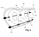
- the leading edge segments 34 may include at least one bracing web 54 attached to the inner surface of the skin 36.
- the bracing webs 54 may extend generally transversely to the longitudinal edges 38, 40 and lend the segment 34 structural rigidity and support. Any manner of internal bracing may be utilized for this reason.
- the bracing webs 54 may be formed from an electrically non-conductive material, and include one or more conductive strip members 56 may run longitudinally within the leading edge segment 34. These conductive strip members 56 may join to the conductive strip members 56 of adjacent leading edge segments 34 by way of any manner of conventional connector 58 so as to define a continuous conductive arrangement for all of the leading edge segments 34, as depicted in FIG. 4 .
- a conductive transmission line or member 60 for each blade may connect all of the blades to a common grounded transmission line 62, as depicted in the wind turbine 200 in FIG. 7 .
- the leading edge segments also provide lightning strike protection to the blades 10, and wind turbine 200.
- the present invention also encompasses a kit for forming a wind turbine rotor blade 10 as depicted in FIGS. 3 and 4 .
- This kit may include the components discussed above in their unassembled or disconnected state.
- the kit may include a first shell component 18, and a second shell component 24, and one or a plurality of the leading edge segments 34 as described above.
- the kit may include any number of the components in a completely unassembled or partially assembled state. With this kit configuration, when assembled, the parts define a blade 10 as depicted in FIGS. 3 and 4 with a leading edge 32 that is continuous and unbroken between bond lines 44 and 46, as depicted in FIG. 5B .
Landscapes
- Engineering & Computer Science (AREA)
- Life Sciences & Earth Sciences (AREA)
- Sustainable Development (AREA)
- Sustainable Energy (AREA)
- Chemical & Material Sciences (AREA)
- Combustion & Propulsion (AREA)
- Mechanical Engineering (AREA)
- General Engineering & Computer Science (AREA)
- Wind Motors (AREA)
Applications Claiming Priority (1)
| Application Number | Priority Date | Filing Date | Title |
|---|---|---|---|
| US12/434,197 US8043065B2 (en) | 2009-05-01 | 2009-05-01 | Wind turbine blade with prefabricated leading edge segments |
Publications (3)
| Publication Number | Publication Date |
|---|---|
| EP2246558A2 true EP2246558A2 (fr) | 2010-11-03 |
| EP2246558A3 EP2246558A3 (fr) | 2014-05-21 |
| EP2246558B1 EP2246558B1 (fr) | 2015-06-10 |
Family
ID=42224558
Family Applications (1)
| Application Number | Title | Priority Date | Filing Date |
|---|---|---|---|
| EP10161199.4A Not-in-force EP2246558B1 (fr) | 2009-05-01 | 2010-04-27 | Pale d'éolienne avec segments du bord d'attaque préfabriqués |
Country Status (4)
| Country | Link |
|---|---|
| US (1) | US8043065B2 (fr) |
| EP (1) | EP2246558B1 (fr) |
| CN (1) | CN101876293B (fr) |
| DK (1) | DK2246558T3 (fr) |
Cited By (7)
| Publication number | Priority date | Publication date | Assignee | Title |
|---|---|---|---|---|
| EP2818701A4 (fr) * | 2012-02-24 | 2015-11-11 | Mitsubishi Heavy Ind Ltd | Pale d'éolienne, procédé de production associé, dispositif de génération d'énergie éolienne l'intégrant, et système de surveillance d'éolienne |
| DK178435B1 (en) * | 2011-01-28 | 2016-02-22 | Gen Electric | Wind turbine blades with a hardened substrate construction |
| EP3275783A1 (fr) * | 2016-07-27 | 2018-01-31 | Bell Helicopter Textron Inc. | Systèmes de protection contre l'érosion de pale de rotor |
| WO2019120412A1 (fr) | 2017-12-20 | 2019-06-27 | Vestas Wind Systems A/S | Pales de turbine éolienne et systèmes et procédés de fabrication utilisant un ensemble pale segmenté |
| WO2020011326A1 (fr) * | 2018-07-09 | 2020-01-16 | Vestas Wind Systems A/S | Améliorations apportées à des pales d'éolienne |
| EP3713749A4 (fr) * | 2017-11-21 | 2021-08-18 | General Electric Company | Composants de pale de rotor d'éolienne et leurs procédés de fabrication |
| WO2021245096A1 (fr) * | 2020-06-02 | 2021-12-09 | LM Wind Power R&D (Holland) B.V. | Pale d'éolienne dotée d'un système de protection contre la foudre |
Families Citing this family (30)
| Publication number | Priority date | Publication date | Assignee | Title |
|---|---|---|---|---|
| GB0815567D0 (en) * | 2008-08-28 | 2008-10-01 | Rolls Royce Plc | An aerofoil |
| CN102308083B (zh) | 2008-12-05 | 2016-04-13 | 模组风能公司 | 高效风轮机叶片 |
| EP2255957B1 (fr) * | 2009-05-25 | 2013-07-10 | LM WP Patent Holding A/S | Procédé de fabrication d'une structure composite avec un élément de renforcement préfabriqué |
| US20110006165A1 (en) * | 2009-07-10 | 2011-01-13 | Peter Ireland | Application of conformal sub boundary layer vortex generators to a foil or aero/ hydrodynamic surface |
| DE102009058101A1 (de) * | 2009-12-12 | 2011-06-16 | Bayer Materialscience Ag | Verwendung von Schichtaufbauten in Windkraftanlagen |
| WO2011077545A1 (fr) * | 2009-12-25 | 2011-06-30 | 三菱重工業株式会社 | Aube rotative de moulin à vent |
| US9500179B2 (en) | 2010-05-24 | 2016-11-22 | Vestas Wind Systems A/S | Segmented wind turbine blades with truss connection regions, and associated systems and methods |
| US8057189B2 (en) * | 2010-12-15 | 2011-11-15 | General Electric Company | Wind turbine blade with modular leading edge |
| GB2497578B (en) * | 2011-12-16 | 2015-01-14 | Vestas Wind Sys As | Wind turbine blades |
| CN103174600A (zh) * | 2011-12-22 | 2013-06-26 | 华锐风电科技(集团)股份有限公司 | 风机叶片 |
| DK2708740T3 (en) | 2012-09-17 | 2017-06-19 | Nordex Energy Gmbh | Wind turbine rotor blade with an electric heater and a line conductor |
| US9470205B2 (en) | 2013-03-13 | 2016-10-18 | Vestas Wind Systems A/S | Wind turbine blades with layered, multi-component spars, and associated systems and methods |
| US9868536B2 (en) * | 2013-10-30 | 2018-01-16 | Goodrich Corporation | Electrical interconnects for ice protection systems |
| KR101541067B1 (ko) | 2013-12-04 | 2015-08-03 | 삼성중공업 주식회사 | 풍력발전기의 블레이드 |
| US10066600B2 (en) | 2014-05-01 | 2018-09-04 | Tpi Composites, Inc. | Wind turbine rotor blade and method of construction |
| DK201570881A1 (da) * | 2015-05-26 | 2017-01-30 | Blade Repair Solutions Ivs | Fremgangsmåde til etablering af erosionsbestandig overfladedel på en vindmøllevinge, fremgangsmåde til dannelse af en erosionsbestandig belægning, vindmøllevinge med eftermonteret belægning i og omkring områder hvor vingen er særligt udsat for erosionsskader, belægning til montering på en vindmøllevinges forkant. |
| EP3303830B1 (fr) * | 2015-05-28 | 2022-09-14 | LM Wind Power A/S | Pale d'éolienne ayant une section d'espacement du bord de fuite |
| GB201509153D0 (en) * | 2015-05-28 | 2015-07-15 | Blade Dynamics Ltd | A composite member |
| US10337490B2 (en) * | 2015-06-29 | 2019-07-02 | General Electric Company | Structural component for a modular rotor blade |
| US20160377052A1 (en) * | 2015-06-29 | 2016-12-29 | General Electric Company | Blade root section for a modular rotor blade and method of manufacturing same |
| US20160377050A1 (en) * | 2015-06-29 | 2016-12-29 | General Electric Company | Modular wind turbine rotor blades and methods of assembling same |
| KR101731951B1 (ko) | 2016-06-21 | 2017-05-11 | 한국항공대학교산학협력단 | 풍력 발전기용 블레이드 |
| WO2018060297A1 (fr) * | 2016-09-27 | 2018-04-05 | Siemens Aktiengesellschaft | Système de couverture pour protéger un bord d'attaque d'une pale de rotor d'éolienne |
| US11536245B2 (en) | 2017-01-26 | 2022-12-27 | General Electric Company | Rotor blade assembly and a wind turbine having the rotor blade assembly |
| JP6418294B1 (ja) * | 2017-08-24 | 2018-11-07 | 株式会社富士通ゼネラル | ロータリ圧縮機 |
| FR3081370B1 (fr) * | 2018-05-22 | 2020-06-05 | Safran Aircraft Engines | Corps d'aube et aube en materiau composite ayant un renfort fibreux compose d'un tissage tridimensionnel et de fibres courtes et leur procede de fabrication |
| CN114072264B (zh) | 2019-07-16 | 2024-06-21 | Lm风力发电公司 | 制造在风力涡轮转子叶片部件中使用的面板的系统和方法 |
| EP3822478A1 (fr) * | 2019-11-15 | 2021-05-19 | Siemens Gamesa Renewable Energy A/S | Procédé de fabrication d'une coque d'une pale d'éolienne ayant une meilleure protection contre l'érosion du bord d'attaque, procédé de fabrication de la pale d'éolienne, coque, pale d'éolienne et éolienne |
| JP7433134B2 (ja) * | 2020-05-22 | 2024-02-19 | 三菱重工業株式会社 | 風車翼、風車、及び、風車翼の製造方法 |
| CN112983756B (zh) * | 2021-03-05 | 2022-05-24 | 天津森聚柯密封涂层材料有限公司 | 一种风能叶片前缘防护加强复合涂膜结构及其制备方法 |
Family Cites Families (25)
| Publication number | Priority date | Publication date | Assignee | Title |
|---|---|---|---|---|
| US2393635A (en) * | 1942-04-17 | 1946-01-29 | Robert H Wendt | Ice removing device for aircraft |
| GB1096294A (en) * | 1964-06-12 | 1967-12-29 | English Electric Co Ltd | Turbine blades |
| US4118147A (en) * | 1976-12-22 | 1978-10-03 | General Electric Company | Composite reinforcement of metallic airfoils |
| BR8008855A (pt) * | 1979-10-03 | 1981-09-01 | Goodrich Co B F | Composto para borda de avanco de aeronaves antecedentes |
| US5314309A (en) * | 1990-05-25 | 1994-05-24 | Anthony Blakeley | Turbine blade with metallic attachment and method of making the same |
| US5430937A (en) | 1994-07-15 | 1995-07-11 | United Technologies Corporation | Apparatus and methods for fabricating a helicopter main rotor blade |
| US5782607A (en) | 1996-12-11 | 1998-07-21 | United Technologies Corporation | Replaceable ceramic blade insert |
| CN1064896C (zh) | 1997-04-16 | 2001-04-25 | 西科尔斯基飞机公司 | 把前缘护套安装在直升飞机的主旋翼叶片分总成上的装置和方法 |
| DK173460B2 (da) | 1998-09-09 | 2004-08-30 | Lm Glasfiber As | Vindmöllevinge med lynafleder |
| DK173607B1 (da) | 1999-06-21 | 2001-04-30 | Lm Glasfiber As | Vindmøllevinge med system til afisning af lynbeskyttelse |
| DE19962454A1 (de) | 1999-12-22 | 2001-07-05 | Aerodyn Eng Gmbh | Rotorblatt für Windenergieanlagen |
| ES2317896T3 (es) | 2000-04-10 | 2009-05-01 | Jomitek Aps | Sistema de proteccion contra rayos, por ejemplo, para un aerogenerador, pala de aerogenerador que presenta un sistema de proteccion contra rayos, procedimiento de creacion de un sistema de proteccion contra rayos y su utilizacion. |
| US6508000B2 (en) * | 2001-02-08 | 2003-01-21 | Siemens Westinghouse Power Corporation | Transient liquid phase bonding repair for advanced turbine blades and vanes |
| CN1975152B (zh) | 2001-07-19 | 2012-03-21 | 维斯塔斯风力系统集团公司 | 风力涡轮机叶片 |
| US6607358B2 (en) * | 2002-01-08 | 2003-08-19 | General Electric Company | Multi-component hybrid turbine blade |
| US7618712B2 (en) * | 2002-09-23 | 2009-11-17 | Siemens Energy, Inc. | Apparatus and method of detecting wear in an abradable coating system |
| WO2004076852A2 (fr) * | 2003-02-28 | 2004-09-10 | Vestas Wind Systems A/S | Procede de fabrication d'une pale d'eolienne, pale d'eolienne, capot avant et utilisation d'un capot avant |
| ES2255454B1 (es) * | 2004-12-15 | 2007-07-01 | Gamesa Eolica, S.A. | Sistema pararrayos para pala de aerogenerador. |
| US20080159870A1 (en) * | 2006-12-14 | 2008-07-03 | Hontek Corporation | Method and coating for protecting and repairing an airfoil surface using molded boots, sheet or tape |
| US7351040B2 (en) | 2006-01-09 | 2008-04-01 | General Electric Company | Methods of making wind turbine rotor blades |
| US7824592B2 (en) * | 2006-09-22 | 2010-11-02 | General Electric Company | Bond line forming method |
| ES2342638B1 (es) * | 2007-02-28 | 2011-05-13 | GAMESA INNOVATION & TECHNOLOGY, S.L. | Una pala de aerogenerador multi-panel. |
| GB0717690D0 (en) * | 2007-09-11 | 2007-10-17 | Blade Dynamics Ltd | Wind turbine blade |
| US8182227B2 (en) * | 2008-02-01 | 2012-05-22 | General Electric Company | Wind turbine blade with lightning receptor |
| US8439647B2 (en) * | 2009-09-08 | 2013-05-14 | Siemens Energy, Inc. | Cooled turbine airfoil fabricated from sheet material |
-
2009
- 2009-05-01 US US12/434,197 patent/US8043065B2/en active Active
-
2010
- 2010-04-27 DK DK10161199.4T patent/DK2246558T3/en active
- 2010-04-27 EP EP10161199.4A patent/EP2246558B1/fr not_active Not-in-force
- 2010-04-30 CN CN201010175160.1A patent/CN101876293B/zh not_active Expired - Fee Related
Non-Patent Citations (1)
| Title |
|---|
| None |
Cited By (10)
| Publication number | Priority date | Publication date | Assignee | Title |
|---|---|---|---|---|
| DK178435B1 (en) * | 2011-01-28 | 2016-02-22 | Gen Electric | Wind turbine blades with a hardened substrate construction |
| EP2818701A4 (fr) * | 2012-02-24 | 2015-11-11 | Mitsubishi Heavy Ind Ltd | Pale d'éolienne, procédé de production associé, dispositif de génération d'énergie éolienne l'intégrant, et système de surveillance d'éolienne |
| EP3275783A1 (fr) * | 2016-07-27 | 2018-01-31 | Bell Helicopter Textron Inc. | Systèmes de protection contre l'érosion de pale de rotor |
| EP3713749A4 (fr) * | 2017-11-21 | 2021-08-18 | General Electric Company | Composants de pale de rotor d'éolienne et leurs procédés de fabrication |
| WO2019120412A1 (fr) | 2017-12-20 | 2019-06-27 | Vestas Wind Systems A/S | Pales de turbine éolienne et systèmes et procédés de fabrication utilisant un ensemble pale segmenté |
| US11499523B2 (en) | 2017-12-20 | 2022-11-15 | Vestas Wind Systems A/S | Wind turbine blades and manufacturing systems and methods using segmented blade assembly |
| WO2020011326A1 (fr) * | 2018-07-09 | 2020-01-16 | Vestas Wind Systems A/S | Améliorations apportées à des pales d'éolienne |
| US11644011B2 (en) | 2018-07-09 | 2023-05-09 | Vestas Wind Systems A/S | Relating to wind turbine blades |
| WO2021245096A1 (fr) * | 2020-06-02 | 2021-12-09 | LM Wind Power R&D (Holland) B.V. | Pale d'éolienne dotée d'un système de protection contre la foudre |
| US12012939B2 (en) | 2020-06-02 | 2024-06-18 | LM Wind Power R&D (Holland) B.V. | Wind blade having a lightning protection system |
Also Published As
| Publication number | Publication date |
|---|---|
| US20100278654A1 (en) | 2010-11-04 |
| US8043065B2 (en) | 2011-10-25 |
| CN101876293B (zh) | 2014-06-04 |
| EP2246558A3 (fr) | 2014-05-21 |
| CN101876293A (zh) | 2010-11-03 |
| EP2246558B1 (fr) | 2015-06-10 |
| DK2246558T3 (en) | 2015-07-27 |
Similar Documents
| Publication | Publication Date | Title |
|---|---|---|
| EP2246558B1 (fr) | Pale d'éolienne avec segments du bord d'attaque préfabriqués | |
| CA2806793C (fr) | Insertion de lame pour une lame de rotor d'eolienne et methodes associees | |
| CA2806784C (fr) | Insertion de lame pour une lame de rotor d'eolienne et methodes associees | |
| CN102454539B (zh) | 用于风力涡轮机的转子叶片节段的接头设计 | |
| EP2249027B1 (fr) | Pale d'éolienne segmentée | |
| CN102287321B (zh) | 风力涡轮机转子叶片接头 | |
| CN113056602B (zh) | 用于接合式风力涡轮转子叶片的翼梁构造 | |
| EP3026259A1 (fr) | Procédés de fabrication d'un bouchon de longeron pour pale de rotor de turbine éolienne | |
| EP3032092A1 (fr) | Embout de longeron pour pale de rotor d'éolienne | |
| EP3682109B1 (fr) | Connexion de joint en biseau de semelle de longeron mal alignée | |
| EP2981708A1 (fr) | Insert de pale pour pale de rotor d'éolienne | |
| EP3874156B1 (fr) | Procédé de rattrapage d'une pale de rotor d'éolienne avec un segment de pointe de pale de remplacement | |
| AU2018446413A1 (en) | Spar cap configuration for a jointed wind turbine blade | |
| EP3884154A1 (fr) | Système de protection contre la foudre pour pale d'éolienne | |
| US20230323854A1 (en) | A connection joint for a split wind turbine blade | |
| WO2023022715A1 (fr) | Configuration de semelle de longeron à aile pour une pale d'éolienne jointe |
Legal Events
| Date | Code | Title | Description |
|---|---|---|---|
| PUAI | Public reference made under article 153(3) epc to a published international application that has entered the european phase |
Free format text: ORIGINAL CODE: 0009012 |
|
| AK | Designated contracting states |
Kind code of ref document: A2 Designated state(s): AT BE BG CH CY CZ DE DK EE ES FI FR GB GR HR HU IE IS IT LI LT LU LV MC MK MT NL NO PL PT RO SE SI SK SM TR |
|
| PUAL | Search report despatched |
Free format text: ORIGINAL CODE: 0009013 |
|
| AK | Designated contracting states |
Kind code of ref document: A3 Designated state(s): AT BE BG CH CY CZ DE DK EE ES FI FR GB GR HR HU IE IS IT LI LT LU LV MC MK MT NL NO PL PT RO SE SI SK SM TR |
|
| RIC1 | Information provided on ipc code assigned before grant |
Ipc: F03D 1/06 20060101AFI20140411BHEP Ipc: F03D 11/00 20060101ALI20140411BHEP |
|
| 17P | Request for examination filed |
Effective date: 20141121 |
|
| RBV | Designated contracting states (corrected) |
Designated state(s): AT BE BG CH CY CZ DE DK EE ES FI FR GB GR HR HU IE IS IT LI LT LU LV MC MK MT NL NO PL PT RO SE SI SK SM TR |
|
| GRAP | Despatch of communication of intention to grant a patent |
Free format text: ORIGINAL CODE: EPIDOSNIGR1 |
|
| INTG | Intention to grant announced |
Effective date: 20150325 |
|
| GRAS | Grant fee paid |
Free format text: ORIGINAL CODE: EPIDOSNIGR3 |
|
| GRAA | (expected) grant |
Free format text: ORIGINAL CODE: 0009210 |
|
| RIN1 | Information on inventor provided before grant (corrected) |
Inventor name: KYRIAKIDES, STEVEN ALAN |
|
| AK | Designated contracting states |
Kind code of ref document: B1 Designated state(s): AT BE BG CH CY CZ DE DK EE ES FI FR GB GR HR HU IE IS IT LI LT LU LV MC MK MT NL NO PL PT RO SE SI SK SM TR |
|
| REG | Reference to a national code |
Ref country code: GB Ref legal event code: FG4D |
|
| REG | Reference to a national code |
Ref country code: CH Ref legal event code: EP |
|
| REG | Reference to a national code |
Ref country code: AT Ref legal event code: REF Ref document number: 731022 Country of ref document: AT Kind code of ref document: T Effective date: 20150715 |
|
| REG | Reference to a national code |
Ref country code: DE Ref legal event code: R096 Ref document number: 602010025137 Country of ref document: DE |
|
| REG | Reference to a national code |
Ref country code: DK Ref legal event code: T3 Effective date: 20150724 |
|
| REG | Reference to a national code |
Ref country code: IE Ref legal event code: FG4D |
|
| PG25 | Lapsed in a contracting state [announced via postgrant information from national office to epo] |
Ref country code: FI Free format text: LAPSE BECAUSE OF FAILURE TO SUBMIT A TRANSLATION OF THE DESCRIPTION OR TO PAY THE FEE WITHIN THE PRESCRIBED TIME-LIMIT Effective date: 20150610 Ref country code: ES Free format text: LAPSE BECAUSE OF FAILURE TO SUBMIT A TRANSLATION OF THE DESCRIPTION OR TO PAY THE FEE WITHIN THE PRESCRIBED TIME-LIMIT Effective date: 20150610 Ref country code: LT Free format text: LAPSE BECAUSE OF FAILURE TO SUBMIT A TRANSLATION OF THE DESCRIPTION OR TO PAY THE FEE WITHIN THE PRESCRIBED TIME-LIMIT Effective date: 20150610 Ref country code: NO Free format text: LAPSE BECAUSE OF FAILURE TO SUBMIT A TRANSLATION OF THE DESCRIPTION OR TO PAY THE FEE WITHIN THE PRESCRIBED TIME-LIMIT Effective date: 20150910 |
|
| REG | Reference to a national code |
Ref country code: AT Ref legal event code: MK05 Ref document number: 731022 Country of ref document: AT Kind code of ref document: T Effective date: 20150610 |
|
| REG | Reference to a national code |
Ref country code: NL Ref legal event code: MP Effective date: 20150610 |
|
| PG25 | Lapsed in a contracting state [announced via postgrant information from national office to epo] |
Ref country code: LV Free format text: LAPSE BECAUSE OF FAILURE TO SUBMIT A TRANSLATION OF THE DESCRIPTION OR TO PAY THE FEE WITHIN THE PRESCRIBED TIME-LIMIT Effective date: 20150610 Ref country code: GR Free format text: LAPSE BECAUSE OF FAILURE TO SUBMIT A TRANSLATION OF THE DESCRIPTION OR TO PAY THE FEE WITHIN THE PRESCRIBED TIME-LIMIT Effective date: 20150911 Ref country code: BG Free format text: LAPSE BECAUSE OF FAILURE TO SUBMIT A TRANSLATION OF THE DESCRIPTION OR TO PAY THE FEE WITHIN THE PRESCRIBED TIME-LIMIT Effective date: 20150910 |
|
| PG25 | Lapsed in a contracting state [announced via postgrant information from national office to epo] |
Ref country code: EE Free format text: LAPSE BECAUSE OF FAILURE TO SUBMIT A TRANSLATION OF THE DESCRIPTION OR TO PAY THE FEE WITHIN THE PRESCRIBED TIME-LIMIT Effective date: 20150610 |
|
| PG25 | Lapsed in a contracting state [announced via postgrant information from national office to epo] |
Ref country code: PL Free format text: LAPSE BECAUSE OF FAILURE TO SUBMIT A TRANSLATION OF THE DESCRIPTION OR TO PAY THE FEE WITHIN THE PRESCRIBED TIME-LIMIT Effective date: 20150610 Ref country code: PT Free format text: LAPSE BECAUSE OF FAILURE TO SUBMIT A TRANSLATION OF THE DESCRIPTION OR TO PAY THE FEE WITHIN THE PRESCRIBED TIME-LIMIT Effective date: 20151012 Ref country code: SK Free format text: LAPSE BECAUSE OF FAILURE TO SUBMIT A TRANSLATION OF THE DESCRIPTION OR TO PAY THE FEE WITHIN THE PRESCRIBED TIME-LIMIT Effective date: 20150610 Ref country code: AT Free format text: LAPSE BECAUSE OF FAILURE TO SUBMIT A TRANSLATION OF THE DESCRIPTION OR TO PAY THE FEE WITHIN THE PRESCRIBED TIME-LIMIT Effective date: 20150610 Ref country code: IS Free format text: LAPSE BECAUSE OF FAILURE TO SUBMIT A TRANSLATION OF THE DESCRIPTION OR TO PAY THE FEE WITHIN THE PRESCRIBED TIME-LIMIT Effective date: 20151010 Ref country code: CZ Free format text: LAPSE BECAUSE OF FAILURE TO SUBMIT A TRANSLATION OF THE DESCRIPTION OR TO PAY THE FEE WITHIN THE PRESCRIBED TIME-LIMIT Effective date: 20150610 Ref country code: RO Free format text: LAPSE BECAUSE OF NON-PAYMENT OF DUE FEES Effective date: 20150610 |
|
| REG | Reference to a national code |
Ref country code: DE Ref legal event code: R097 Ref document number: 602010025137 Country of ref document: DE |
|
| PLBE | No opposition filed within time limit |
Free format text: ORIGINAL CODE: 0009261 |
|
| STAA | Information on the status of an ep patent application or granted ep patent |
Free format text: STATUS: NO OPPOSITION FILED WITHIN TIME LIMIT |
|
| PG25 | Lapsed in a contracting state [announced via postgrant information from national office to epo] |
Ref country code: IT Free format text: LAPSE BECAUSE OF FAILURE TO SUBMIT A TRANSLATION OF THE DESCRIPTION OR TO PAY THE FEE WITHIN THE PRESCRIBED TIME-LIMIT Effective date: 20150610 |
|
| 26N | No opposition filed |
Effective date: 20160311 |
|
| PG25 | Lapsed in a contracting state [announced via postgrant information from national office to epo] |
Ref country code: SI Free format text: LAPSE BECAUSE OF FAILURE TO SUBMIT A TRANSLATION OF THE DESCRIPTION OR TO PAY THE FEE WITHIN THE PRESCRIBED TIME-LIMIT Effective date: 20150610 |
|
| PG25 | Lapsed in a contracting state [announced via postgrant information from national office to epo] |
Ref country code: BE Free format text: LAPSE BECAUSE OF NON-PAYMENT OF DUE FEES Effective date: 20160430 |
|
| REG | Reference to a national code |
Ref country code: CH Ref legal event code: PL |
|
| GBPC | Gb: european patent ceased through non-payment of renewal fee |
Effective date: 20160427 |
|
| PG25 | Lapsed in a contracting state [announced via postgrant information from national office to epo] |
Ref country code: LU Free format text: LAPSE BECAUSE OF FAILURE TO SUBMIT A TRANSLATION OF THE DESCRIPTION OR TO PAY THE FEE WITHIN THE PRESCRIBED TIME-LIMIT Effective date: 20160427 Ref country code: BE Free format text: LAPSE BECAUSE OF FAILURE TO SUBMIT A TRANSLATION OF THE DESCRIPTION OR TO PAY THE FEE WITHIN THE PRESCRIBED TIME-LIMIT Effective date: 20150610 |
|
| REG | Reference to a national code |
Ref country code: IE Ref legal event code: MM4A |
|
| REG | Reference to a national code |
Ref country code: FR Ref legal event code: ST Effective date: 20161230 |
|
| PG25 | Lapsed in a contracting state [announced via postgrant information from national office to epo] |
Ref country code: LI Free format text: LAPSE BECAUSE OF NON-PAYMENT OF DUE FEES Effective date: 20160430 Ref country code: CH Free format text: LAPSE BECAUSE OF NON-PAYMENT OF DUE FEES Effective date: 20160430 Ref country code: GB Free format text: LAPSE BECAUSE OF NON-PAYMENT OF DUE FEES Effective date: 20160427 Ref country code: FR Free format text: LAPSE BECAUSE OF NON-PAYMENT OF DUE FEES Effective date: 20160502 |
|
| PG25 | Lapsed in a contracting state [announced via postgrant information from national office to epo] |
Ref country code: IE Free format text: LAPSE BECAUSE OF NON-PAYMENT OF DUE FEES Effective date: 20160427 |
|
| PG25 | Lapsed in a contracting state [announced via postgrant information from national office to epo] |
Ref country code: NL Free format text: LAPSE BECAUSE OF FAILURE TO SUBMIT A TRANSLATION OF THE DESCRIPTION OR TO PAY THE FEE WITHIN THE PRESCRIBED TIME-LIMIT Effective date: 20150610 Ref country code: SE Free format text: LAPSE BECAUSE OF FAILURE TO SUBMIT A TRANSLATION OF THE DESCRIPTION OR TO PAY THE FEE WITHIN THE PRESCRIBED TIME-LIMIT Effective date: 20150610 |
|
| PG25 | Lapsed in a contracting state [announced via postgrant information from national office to epo] |
Ref country code: HU Free format text: LAPSE BECAUSE OF FAILURE TO SUBMIT A TRANSLATION OF THE DESCRIPTION OR TO PAY THE FEE WITHIN THE PRESCRIBED TIME-LIMIT; INVALID AB INITIO Effective date: 20100427 Ref country code: SM Free format text: LAPSE BECAUSE OF FAILURE TO SUBMIT A TRANSLATION OF THE DESCRIPTION OR TO PAY THE FEE WITHIN THE PRESCRIBED TIME-LIMIT Effective date: 20150610 Ref country code: CY Free format text: LAPSE BECAUSE OF FAILURE TO SUBMIT A TRANSLATION OF THE DESCRIPTION OR TO PAY THE FEE WITHIN THE PRESCRIBED TIME-LIMIT Effective date: 20150610 |
|
| PG25 | Lapsed in a contracting state [announced via postgrant information from national office to epo] |
Ref country code: MK Free format text: LAPSE BECAUSE OF FAILURE TO SUBMIT A TRANSLATION OF THE DESCRIPTION OR TO PAY THE FEE WITHIN THE PRESCRIBED TIME-LIMIT Effective date: 20150610 Ref country code: HR Free format text: LAPSE BECAUSE OF FAILURE TO SUBMIT A TRANSLATION OF THE DESCRIPTION OR TO PAY THE FEE WITHIN THE PRESCRIBED TIME-LIMIT Effective date: 20150610 Ref country code: MC Free format text: LAPSE BECAUSE OF FAILURE TO SUBMIT A TRANSLATION OF THE DESCRIPTION OR TO PAY THE FEE WITHIN THE PRESCRIBED TIME-LIMIT Effective date: 20150610 Ref country code: TR Free format text: LAPSE BECAUSE OF FAILURE TO SUBMIT A TRANSLATION OF THE DESCRIPTION OR TO PAY THE FEE WITHIN THE PRESCRIBED TIME-LIMIT Effective date: 20150610 Ref country code: MT Free format text: LAPSE BECAUSE OF NON-PAYMENT OF DUE FEES Effective date: 20160430 |
|
| P01 | Opt-out of the competence of the unified patent court (upc) registered |
Effective date: 20230522 |
|
| REG | Reference to a national code |
Ref country code: DE Ref legal event code: R081 Ref document number: 602010025137 Country of ref document: DE Owner name: GENERAL ELECTRIC RENOVABLES ESPANA S.L., ES Free format text: FORMER OWNER: GENERAL ELECTRIC CO., SCHENECTADY, N.Y., US Ref country code: DE Ref legal event code: R081 Ref document number: 602010025137 Country of ref document: DE Owner name: LM WIND POWER A/S, DK Free format text: FORMER OWNER: GENERAL ELECTRIC CO., SCHENECTADY, N.Y., US |
|
| PGFP | Annual fee paid to national office [announced via postgrant information from national office to epo] |
Ref country code: DK Payment date: 20240320 Year of fee payment: 15 |
|
| PGFP | Annual fee paid to national office [announced via postgrant information from national office to epo] |
Ref country code: DE Payment date: 20240320 Year of fee payment: 15 |
|
| REG | Reference to a national code |
Ref country code: DE Ref legal event code: R081 Ref document number: 602010025137 Country of ref document: DE Owner name: GENERAL ELECTRIC RENOVABLES ESPANA S.L., ES Free format text: FORMER OWNER: LM WIND POWER A/S, KOLDING, DK |
|
| REG | Reference to a national code |
Ref country code: DE Ref legal event code: R119 Ref document number: 602010025137 Country of ref document: DE |
|
| REG | Reference to a national code |
Ref country code: DK Ref legal event code: EBP Effective date: 20250430 |
|
| PG25 | Lapsed in a contracting state [announced via postgrant information from national office to epo] |
Ref country code: DE Free format text: LAPSE BECAUSE OF NON-PAYMENT OF DUE FEES Effective date: 20251104 |
|
| PG25 | Lapsed in a contracting state [announced via postgrant information from national office to epo] |
Ref country code: DK Free format text: LAPSE BECAUSE OF NON-PAYMENT OF DUE FEES Effective date: 20250430 |