EP2246560A1 - Appareil générateur pour dépôt de stockage de radiateur chaud - Google Patents
Appareil générateur pour dépôt de stockage de radiateur chaud Download PDFInfo
- Publication number
- EP2246560A1 EP2246560A1 EP09707803A EP09707803A EP2246560A1 EP 2246560 A1 EP2246560 A1 EP 2246560A1 EP 09707803 A EP09707803 A EP 09707803A EP 09707803 A EP09707803 A EP 09707803A EP 2246560 A1 EP2246560 A1 EP 2246560A1
- Authority
- EP
- European Patent Office
- Prior art keywords
- building
- hot
- temperature heat
- heat radiator
- air
- Prior art date
- Legal status (The legal status is an assumption and is not a legal conclusion. Google has not performed a legal analysis and makes no representation as to the accuracy of the status listed.)
- Withdrawn
Links
Images










Classifications
-
- F—MECHANICAL ENGINEERING; LIGHTING; HEATING; WEAPONS; BLASTING
- F03—MACHINES OR ENGINES FOR LIQUIDS; WIND, SPRING, OR WEIGHT MOTORS; PRODUCING MECHANICAL POWER OR A REACTIVE PROPULSIVE THRUST, NOT OTHERWISE PROVIDED FOR
- F03D—WIND MOTORS
- F03D9/00—Adaptations of wind motors for special use; Combinations of wind motors with apparatus driven thereby; Wind motors specially adapted for installation in particular locations
- F03D9/20—Wind motors characterised by the driven apparatus
- F03D9/25—Wind motors characterised by the driven apparatus the apparatus being an electrical generator
-
- F—MECHANICAL ENGINEERING; LIGHTING; HEATING; WEAPONS; BLASTING
- F03—MACHINES OR ENGINES FOR LIQUIDS; WIND, SPRING, OR WEIGHT MOTORS; PRODUCING MECHANICAL POWER OR A REACTIVE PROPULSIVE THRUST, NOT OTHERWISE PROVIDED FOR
- F03D—WIND MOTORS
- F03D9/00—Adaptations of wind motors for special use; Combinations of wind motors with apparatus driven thereby; Wind motors specially adapted for installation in particular locations
- F03D9/30—Wind motors specially adapted for installation in particular locations
- F03D9/34—Wind motors specially adapted for installation in particular locations on stationary objects or on stationary man-made structures
- F03D9/35—Wind motors specially adapted for installation in particular locations on stationary objects or on stationary man-made structures within towers, e.g. using chimney effects
- F03D9/37—Wind motors specially adapted for installation in particular locations on stationary objects or on stationary man-made structures within towers, e.g. using chimney effects with means for enhancing the air flow within the tower, e.g. by heating
-
- F—MECHANICAL ENGINEERING; LIGHTING; HEATING; WEAPONS; BLASTING
- F03—MACHINES OR ENGINES FOR LIQUIDS; WIND, SPRING, OR WEIGHT MOTORS; PRODUCING MECHANICAL POWER OR A REACTIVE PROPULSIVE THRUST, NOT OTHERWISE PROVIDED FOR
- F03G—SPRING, WEIGHT, INERTIA OR LIKE MOTORS; MECHANICAL-POWER PRODUCING DEVICES OR MECHANISMS, NOT OTHERWISE PROVIDED FOR OR USING ENERGY SOURCES NOT OTHERWISE PROVIDED FOR
- F03G6/00—Devices for producing mechanical power from solar energy
- F03G6/02—Devices for producing mechanical power from solar energy using a single state working fluid
- F03G6/04—Devices for producing mechanical power from solar energy using a single state working fluid gaseous
- F03G6/045—Devices for producing mechanical power from solar energy using a single state working fluid gaseous by producing an updraft of heated gas or a downdraft of cooled gas, e.g. air driving an engine
-
- F—MECHANICAL ENGINEERING; LIGHTING; HEATING; WEAPONS; BLASTING
- F03—MACHINES OR ENGINES FOR LIQUIDS; WIND, SPRING, OR WEIGHT MOTORS; PRODUCING MECHANICAL POWER OR A REACTIVE PROPULSIVE THRUST, NOT OTHERWISE PROVIDED FOR
- F03G—SPRING, WEIGHT, INERTIA OR LIKE MOTORS; MECHANICAL-POWER PRODUCING DEVICES OR MECHANISMS, NOT OTHERWISE PROVIDED FOR OR USING ENERGY SOURCES NOT OTHERWISE PROVIDED FOR
- F03G6/00—Devices for producing mechanical power from solar energy
- F03G6/071—Devices for producing mechanical power from solar energy with energy storage devices
-
- F—MECHANICAL ENGINEERING; LIGHTING; HEATING; WEAPONS; BLASTING
- F05—INDEXING SCHEMES RELATING TO ENGINES OR PUMPS IN VARIOUS SUBCLASSES OF CLASSES F01-F04
- F05B—INDEXING SCHEME RELATING TO WIND, SPRING, WEIGHT, INERTIA OR LIKE MOTORS, TO MACHINES OR ENGINES FOR LIQUIDS COVERED BY SUBCLASSES F03B, F03D AND F03G
- F05B2220/00—Application
- F05B2220/60—Application making use of surplus or waste energy
- F05B2220/602—Application making use of surplus or waste energy with energy recovery turbines
-
- F—MECHANICAL ENGINEERING; LIGHTING; HEATING; WEAPONS; BLASTING
- F05—INDEXING SCHEMES RELATING TO ENGINES OR PUMPS IN VARIOUS SUBCLASSES OF CLASSES F01-F04
- F05B—INDEXING SCHEME RELATING TO WIND, SPRING, WEIGHT, INERTIA OR LIKE MOTORS, TO MACHINES OR ENGINES FOR LIQUIDS COVERED BY SUBCLASSES F03B, F03D AND F03G
- F05B2240/00—Components
- F05B2240/90—Mounting on supporting structures or systems
- F05B2240/91—Mounting on supporting structures or systems on a stationary structure
- F05B2240/911—Mounting on supporting structures or systems on a stationary structure already existing for a prior purpose
- F05B2240/9111—Mounting on supporting structures or systems on a stationary structure already existing for a prior purpose which is a chimney
-
- Y—GENERAL TAGGING OF NEW TECHNOLOGICAL DEVELOPMENTS; GENERAL TAGGING OF CROSS-SECTIONAL TECHNOLOGIES SPANNING OVER SEVERAL SECTIONS OF THE IPC; TECHNICAL SUBJECTS COVERED BY FORMER USPC CROSS-REFERENCE ART COLLECTIONS [XRACs] AND DIGESTS
- Y02—TECHNOLOGIES OR APPLICATIONS FOR MITIGATION OR ADAPTATION AGAINST CLIMATE CHANGE
- Y02B—CLIMATE CHANGE MITIGATION TECHNOLOGIES RELATED TO BUILDINGS, e.g. HOUSING, HOUSE APPLIANCES OR RELATED END-USER APPLICATIONS
- Y02B10/00—Integration of renewable energy sources in buildings
- Y02B10/20—Solar thermal
-
- Y—GENERAL TAGGING OF NEW TECHNOLOGICAL DEVELOPMENTS; GENERAL TAGGING OF CROSS-SECTIONAL TECHNOLOGIES SPANNING OVER SEVERAL SECTIONS OF THE IPC; TECHNICAL SUBJECTS COVERED BY FORMER USPC CROSS-REFERENCE ART COLLECTIONS [XRACs] AND DIGESTS
- Y02—TECHNOLOGIES OR APPLICATIONS FOR MITIGATION OR ADAPTATION AGAINST CLIMATE CHANGE
- Y02B—CLIMATE CHANGE MITIGATION TECHNOLOGIES RELATED TO BUILDINGS, e.g. HOUSING, HOUSE APPLIANCES OR RELATED END-USER APPLICATIONS
- Y02B10/00—Integration of renewable energy sources in buildings
- Y02B10/30—Wind power
-
- Y—GENERAL TAGGING OF NEW TECHNOLOGICAL DEVELOPMENTS; GENERAL TAGGING OF CROSS-SECTIONAL TECHNOLOGIES SPANNING OVER SEVERAL SECTIONS OF THE IPC; TECHNICAL SUBJECTS COVERED BY FORMER USPC CROSS-REFERENCE ART COLLECTIONS [XRACs] AND DIGESTS
- Y02—TECHNOLOGIES OR APPLICATIONS FOR MITIGATION OR ADAPTATION AGAINST CLIMATE CHANGE
- Y02B—CLIMATE CHANGE MITIGATION TECHNOLOGIES RELATED TO BUILDINGS, e.g. HOUSING, HOUSE APPLIANCES OR RELATED END-USER APPLICATIONS
- Y02B10/00—Integration of renewable energy sources in buildings
- Y02B10/70—Hybrid systems, e.g. uninterruptible or back-up power supplies integrating renewable energies
-
- Y—GENERAL TAGGING OF NEW TECHNOLOGICAL DEVELOPMENTS; GENERAL TAGGING OF CROSS-SECTIONAL TECHNOLOGIES SPANNING OVER SEVERAL SECTIONS OF THE IPC; TECHNICAL SUBJECTS COVERED BY FORMER USPC CROSS-REFERENCE ART COLLECTIONS [XRACs] AND DIGESTS
- Y02—TECHNOLOGIES OR APPLICATIONS FOR MITIGATION OR ADAPTATION AGAINST CLIMATE CHANGE
- Y02E—REDUCTION OF GREENHOUSE GAS [GHG] EMISSIONS, RELATED TO ENERGY GENERATION, TRANSMISSION OR DISTRIBUTION
- Y02E10/00—Energy generation through renewable energy sources
- Y02E10/40—Solar thermal energy, e.g. solar towers
- Y02E10/46—Conversion of thermal power into mechanical power, e.g. Rankine, Stirling or solar thermal engines
-
- Y—GENERAL TAGGING OF NEW TECHNOLOGICAL DEVELOPMENTS; GENERAL TAGGING OF CROSS-SECTIONAL TECHNOLOGIES SPANNING OVER SEVERAL SECTIONS OF THE IPC; TECHNICAL SUBJECTS COVERED BY FORMER USPC CROSS-REFERENCE ART COLLECTIONS [XRACs] AND DIGESTS
- Y02—TECHNOLOGIES OR APPLICATIONS FOR MITIGATION OR ADAPTATION AGAINST CLIMATE CHANGE
- Y02E—REDUCTION OF GREENHOUSE GAS [GHG] EMISSIONS, RELATED TO ENERGY GENERATION, TRANSMISSION OR DISTRIBUTION
- Y02E10/00—Energy generation through renewable energy sources
- Y02E10/70—Wind energy
- Y02E10/72—Wind turbines with rotation axis in wind direction
-
- Y—GENERAL TAGGING OF NEW TECHNOLOGICAL DEVELOPMENTS; GENERAL TAGGING OF CROSS-SECTIONAL TECHNOLOGIES SPANNING OVER SEVERAL SECTIONS OF THE IPC; TECHNICAL SUBJECTS COVERED BY FORMER USPC CROSS-REFERENCE ART COLLECTIONS [XRACs] AND DIGESTS
- Y02—TECHNOLOGIES OR APPLICATIONS FOR MITIGATION OR ADAPTATION AGAINST CLIMATE CHANGE
- Y02E—REDUCTION OF GREENHOUSE GAS [GHG] EMISSIONS, RELATED TO ENERGY GENERATION, TRANSMISSION OR DISTRIBUTION
- Y02E10/00—Energy generation through renewable energy sources
- Y02E10/70—Wind energy
- Y02E10/728—Onshore wind turbines
-
- Y—GENERAL TAGGING OF NEW TECHNOLOGICAL DEVELOPMENTS; GENERAL TAGGING OF CROSS-SECTIONAL TECHNOLOGIES SPANNING OVER SEVERAL SECTIONS OF THE IPC; TECHNICAL SUBJECTS COVERED BY FORMER USPC CROSS-REFERENCE ART COLLECTIONS [XRACs] AND DIGESTS
- Y02—TECHNOLOGIES OR APPLICATIONS FOR MITIGATION OR ADAPTATION AGAINST CLIMATE CHANGE
- Y02P—CLIMATE CHANGE MITIGATION TECHNOLOGIES IN THE PRODUCTION OR PROCESSING OF GOODS
- Y02P70/00—Climate change mitigation technologies in the production process for final industrial or consumer products
- Y02P70/50—Manufacturing or production processes characterised by the final manufactured product
Definitions
- the present invention relates a high-temperature radiator storage yard generating apparatus that is configured to enable efficient recovery of heat retained by a high-temperature radiator that is cooled by natural radiation of heat after manufacture in a high-temperature state in various types of equipment, and thereby to enable efficient use of the heat for power generation.
- the present application claims the benefit of Japanese Patent Application 2008-26720 filed February 6, 2008 in Japan, Japanese Patent Application 2008-320242 filed in Japan on December 16, 2008, Japanese Patent Application 2008-323231 filed in Japan on December 19, 2008, and Japanese Patent Application 2008-332066 filed in Japan on December 26, 2008, the entire disclosure of which is incorporated by reference herein.
- the molten steel is continuously cast to thereby form a steel billet such as a stab or the like, then the steel billet is hot-rolled, and the rolled sheet plate is formed into a hot-rolled coil rolled into a coil shape. Thereafter, an iron and steel product such as steel stock is manufactured by subjecting the hot-rolled coils to a predetermined processing such as cold rolling or the like.
- steel billet such as a slab or the like that is continuously cast from molten steel during the process of manufacturing an iron and steel product reaches a temperature in excess of 1000 ° C immediately after manufacture. Consequently the steel billet such as a slab or the like is transferred to a storage yard such as a slab yard for temporary storage before transfer to the subsequent rolling process and the residual heat in the steel billet such as a slab caused by the continuous casting is allowed to radiate. Normally, the billets are transferred to the next process in the order in which they entered the storage yard.
- the hot-rolled coils immediately after manufacture reach a high temperature of 500 - 600 °C, they are transferred to a coil yard to allow radiation of residual heat caused by the hot-rolling process and temporarily stored until transfer to a subsequent process. Normally, the hot-rolled coils are transferred to the next process in the order in which they entered the coil yard.
- a thermal power plant building and wind power generation system has been proposed in which a wind power generation means that generates power using an ascending airflow produced by heat from the power generation equipment and an exhaust port by which the ascending airflow is discharged are provided in a thermal power plant building that houses power generating equipment. Furthermore this system also proposes a configuration of the thermal power plant building into a boiler building or turbine building. According to the thermal power plant building and wind power generation system, heat produced by the power generation equipment disposed in the thermal power plant building can be used for power generation by a wind power generating means that uses an ascending airflow produced by air heated by radiation of heat (for example, refer to Patent Literature 1).
- a draft-duct type power generation apparatus which is formed by a solar collector that uses solar radiation to heat air, a draft duct (chimney) that introduces air heated by the solar collector to thereby produce an ascending airflow caused by the buoyancy of heated air, and a power generating turbine that is disposed in the draft duct and generates power by using the ascending airflow produced in the draft duct (for example, refer to Patent Literature 2).
- the draft duct power generation apparatus described in Patent Literature 2 uses solar light as a heat source and therefore there is no teaching whatsoever regarding the recovery of heat radiated from a high-temperature heat radiating body such as an intermediate iron and steel product manufactured under a high-temperature condition.
- the invention was founded on the insights that a high heat density can be obtained from high-temperature heat radiating bodies that are accumulated and stored in a temporary storage yard for high-temperature heat radiating bodies manufactured under high-temperature conditions by introduction of heat during manufacture, the sum of the heat amount in the stored high-temperature heat radiating bodies undergoes little variation, and almost all heat radiation occurs in the yard. Therefore an air temperature in the storage yard can be stably and efficiently increased.
- the retained energy in the high-temperature heat radiating bodies enables stable power generation with little waste.
- an object of the present invention is to provide a high-temperature radiator storage yard generating apparatus for that enables power generation by efficient recovery of heat retained in a high-temperature radiator that is manufactured under a high-temperature condition by introduction of heat. Furthermore another object of the present invention is to provide a high-temperature radiator storage yard generating apparatus that can also be employed to an existing high-temperature radiator storage yard without interference to the existing operation of the high-temperature radiator storage yard and that does not require large renovation works on the ceiling portion of the building.
- Another object of the present invention is a high-temperature radiator storage yard generating apparatus that increases the temperature increase of air that is heated by heating convection with the high-temperature radiator by increasing the heat exchange time between the air entering into the high-temperature radiator storage yard and the high-temperature radiator stored in the high-temperature radiator storage yard, and thereby further reduce the density of ascending air in the air discharge tower, increase the operating energy of heated air ascending in the air discharge tower and further increase the energy recoverable by the power generating turbine.
- a further object of the present invention is to provide a high-temperature radiator storage yard generating apparatus that, in comparison to using only natural convection heating, increases the total amount of gas flow heated in the high-temperature heat radiator storage yard to produce buoyancy and thereby further increases the energy recoverable by the power generating turbine.
- the present invention has a configuration in which a chimney having an upper portion configured into a cylindrical portion extending upwardly is disposed in a ceiling portion of a building of a high-temperature radiator storage yard that temporarily accumulates and stores a high-temperature radiator, and a power generating turbine that generates power with an ascending airflow is disposed at a predetermined position in the cylindrical portion in the chimney to thereby generate power with an ascending airflow.
- an intake port may be provided in a lower portion of a side wall of the building that houses the high-temperature radiator storage yard.
- radiant heat-receiving panels separated by a predetermined space from facing side walls may be provided on an inner side of the side wall of the building that houses the high-temperature radiator storage yard.
- the radiant heat-receiving panels may be disposed vertically at a predetermined position in an upper portion of the building that houses the high-temperature radiator storage yard that does not interfere with the stored high-temperature radiator.
- the high-temperature heat radiating body may be an intermediate iron and steel product in an iron mill and the high-temperature radiator storage yard may be a storage yard for temporary storage of the intermediate iron and steel product.
- the intermediate iron and steel product may be a hot-rolled coil manufactured by hot-rolling equipment in the iron mill, and the storage yard for temporarily storing the intermediate iron and steel product may be a coil yard.
- the high-temperature heat radiator may be a hot-rolled coil manufactured by hot-rolling equipment in the iron mill, and an end portion in the exporting direction of the hot-rolled coil in the building that houses the hot-rolling equipment may communicate with and be connected to a side portion of the building that houses the high-temperature heat radiator storage yard that temporarily stores and accumulates the hot-rolled coils to enable air intake.
- the radiation heat receiving panels may be provided on an inner side of a side wall except for a side portion of the hot-rolling equipment forming a connecting portion with the building in the building that houses the high-temperature heat radiator storage yard that temporarily stores and accumulates the hot-rolled coils.
- a gridiron type member may be provided on the floor of the building for the high-temperature heat radiator storage yard and the high-temperature heat radiator may be loaded thereon.
- an insulting member having high-temperature resistant properties may be arranged on an inner bottom portion of the building for the high-temperature heat radiator storage yard.
- a predetermined position of the building for the high-temperature heat radiator storage yard that temporarily accumulates and stores the high-temperature heat radiator communicates with and is connected through a connecting duct to a lower end portion of the air discharge tower that extends in a vertical direction and is provided on an outer portion separately to the building. Furthermore a power generating turbine is provided at a predetermined position on the air discharge tower or the connecting duct, and air imparted with buoyancy by heating in the building is introduced into the air discharge tower through the connecting duct to thereby generate power by the airflow passing through the air discharge tower.
- a predetermined position of the building for the high-temperature heat radiator storage yard that temporarily accumulates and stores the high-temperature heat radiator communicates with and is connected through a connecting duct to a lower end portion of the air discharge tower that extends in a vertical direction and is provided on an outer portion separately to the building.
- a water spraying nozzle for spraying water onto the high-temperature heat radiator stored in the building is provided at a predetermined position on a ceiling portion in the building and a power generating turbine is provided at a predetermined position on the air discharge tower or the connecting duct.
- steam that is produced by evaporation of water sprayed from the water spraying nozzle resulting from heat retained in the high-temperature heat radiator and air imparted with buoyancy by heating in the building are introduced into the air discharge tower through the connecting duct to thereby generate power by the air and the steam passing through the air discharge tower.
- a funnel for air discharge equipment may be used as the air discharge tower that is separate from the building.
- the high-temperature heat radiator may be an intermediate iron and steel product in the iron mill
- the building that houses the high-temperature heat radiator storage yard that communicates with and is connected through a connecting duct to a lower end portion of the air discharge tower may be the building that houses the storage yard that temporarily stores and accumulates the intermediate iron and steel product.
- the intermediate iron and steel product forming the high-temperature heat radiator is a hot-rolled coil that is manufactured by hot-rolling equipment in the iron mill and the building that houses the storage yard acting as the building for the storage yard of the high-temperature heat radiator that temporarily stores and accumulates the intermediate iron and steel product and communicates with and is connected through a connecting duct to a lower end portion of the air discharge tower may be a building that houses the coil yard.
- the end portion in the exporting direction of the hot-rolled coil in the building that houses the hot-rolling equipment may communicate with and be connected to enable air intake with a side portion of the building that houses the coil yard that temporarily stores and accumulates the intermediate iron and steel product and is connected through a connecting duct to a lower end portion of the air discharge tower.
- a lower end portion of an air discharge tower extending vertically and provided on an upper side of the building communicates with and is connected to a central portion of the ceiling of the building of the high-temperature heat radiator storage yard that temporarily stores and accumulates high-temperature heat radiator.
- air ducts enabling inflow of air in a horizontal direction along an inner face of the building peripheral wall may be provided at a plurality of predetermined positions on the peripheral wall of the building so that the inflow direction of air inflowing in a horizontal direction into the building through each air duct meets at either one of a clockwise or a counterclockwise air circulation direction when viewed on a plane, and furthermore a power generating turbine may be provided a predetermined position on the air discharge tower.
- a lower end portion of the air discharge tower extending vertically and provided on an upper side of the building communicates with and is connected to a central portion of the ceiling of the building of the high-temperature heat radiator storage yard that temporarily stores and accumulates high-temperature heat radiating bodies.
- a water spraying nozzle for spraying water onto the high-temperature heat radiator stored in the building is provided at a predetermined position on the ceiling portion in the building.
- air ducts enabling inflow of air in a horizontal direction along an inner face of the building peripheral wall are provided at a plurality of predetermined positions on the peripheral wall of the building so that the inflow direction of air inflowing in a horizontal direction into the building through each air duct meets at either one of a clockwise or a counterclockwise air circulation direction when viewed on a plane, and furthermore a power generating turbine is provided a predetermined position on the air discharge tower.
- the high-temperature heat radiator may be an intermediate iron and steel product in the iron mill
- the building of the high-temperature heat radiator storage yard provided with an air duct at a plurality of predetermined positions on a peripheral wall may be a building of the storage yard that temporarily stores and accumulates the intermediate iron and steel product.
- the intermediate iron and steel product acting as the high-temperature heat radiator may be a hot-rolled coil manufactured by hot-rolling equipment in the iron mill, and the building of the storage yard acting as the high-temperature heat radiator storage yard temporarily storing the intermediate iron and steel product and provided with an air duct at a plurality of predetermined positions on a peripheral wall may be a building of a coil yard.
- a lower end portion of an air discharge tower extending vertically and provided on an upper side of the building communicates with and is connected to a predetermined position on the ceiling of the building of the high-temperature heat radiator storage yard that temporarily stores and accumulates high-temperature heat radiator.
- a water spraying nozzle is provided at a predetermined position on a ceiling portion of an inner portion of the building, and is connected through a water supply line with a water pump.
- a power generating turbine may be disposed at a predetermined position of the air discharge tower.
- a lower end portion of an air discharge tower extending vertically and provided on an upper side of the building communicates with and is connected to a predetermined position on the ceiling of the building of the high-temperature heat radiator storage yard that temporarily stores and accumulates high-temperature heat radiator.
- a water spraying nozzle is provided at a predetermined position on a ceiling portion of an inner portion of the building, and is connected through a water supply line with a rainwater tank provided at a higher position than the position at which the water spraying nozzle is disposed.
- a power generating turbine may be disposed at a predetermined position of the air discharge tower.
- a plurality of water spraying nozzles may be provided a predetermined position on a ceiling portion of an inner portion of the building, and a water supply valve may be provided corresponding to each of the water spraying nozzles.
- the high-temperature heat radiator may be an intermediate iron and steel product in an iron mill
- the building of the high-temperature heat radiator storage yard in which a water spraying nozzle is provided at a predetermined position on a ceiling portion may be a building of a storage yard for temporary storage of the intermediate iron and steel product.
- the intermediate iron and steel product acting as the high-temperature heat radiator may be a hot-rolled coil manufactured by hot-rolling equipment in the iron mill, and the building of the storage yard acting as the building that houses the high-temperature heat radiator storage yard for temporary storage of the high-temperature heat radiator and in which a water spraying nozzle is provided at a predetermined position on a ceiling portion may be a building of the coil yard.
- the high-temperature heat radiator storage yard generating apparatus displays the following excellent effects.
- FIG. 1 shows an embodiment of a high-temperature heat radiator storage yard generation apparatus for according to the present invention which is applied to a coil yard 1 which acts as a high-temperature heat radiator storage yard for the temporary storage of a hot-rolled coil 2 which is an intermediate iron and steel product acting as a high-temperature heat radiator that is manufactured using the hot-rolling equipment of an integrated iron and steel mill or the like, and the configuration thereof will be described below.
- a chimney 4 which has a lower portion substantially in the shape of a pyramid and an upper portion forming a cylindrical portion 4a that extends with a predetermined dimension upwardly is provided in a ceiling portion of a building 3 of a coil yard that is used for temporary storage of the hot-rolled coil 2 that is manufactured by introducing heat via hot-rolling equipment until transfer to a subsequent process.
- a power generating turbine 5 is provided at a predetermined position on the cylindrical portion 4a.
- an intake duct 7 is provided in a lower end portion of the four side walls 6 of the building 3.
- an export conveying port and an import conveying port for the hot-rolled coils 2 in the coil yard building 3 may be provided in a predetermined side wall 6 of the coil yard building 3 and may be provided with an opening and closing door. Furthermore an air intake duct similar to the above air intake duct 7 may be provided in a lower end portion of the door of the export conveying port and the import conveying port.
- a conveying means (not shown) for the hot-rolled coils 2 may be provided in the building 3.
- the hot-rolled coil 2 that is manufactured by a hot-rolling process causing introduction of heat from hot-rolling equipment (not shown) is imported by the import conveying port (not shown) into the building 3 of the coil yard 1 provides with a high-temperature heat radiator storage yard generating apparatus as described above, and is temporarily accumulated and stored until transfer to a subsequent processing step.
- the heat retained in each hot-rolled coil 2 in the coil yard building 3 undergoes heat transfer into the air in the building 3 mainly due to convection heating, and thereby the air in the building 3 is heated.
- the heated air undergoes a reduction in density and displaces towards the chimney 4 in the ceiling portion by ascending in the building 3 due to the resulting buoyancy.
- an ascending airflow is produced that; after ascending towards the chimney 4 through an inner portion of the building 3 from the intake duct 7 provided in the four side walls 6, flows from a lower position upwardly in the cylindrical portion 4a.
- This ascending airflow drives a power generating turbine 5 that are provided in the cylindrical portion 4a of the chimney 4 to thereby execute wind-power power generation.
- the high-temperature heat radiator storage yard generation apparatus According to the above manner, according to the high-temperature heat radiator storage yard generation apparatus according to the present invention, accumulation and storage of high-temperature hot-rolled coils 2 immediately after manufacture enables efficient heating of air using heat retained in hot-rolled coils 2 in the building 3 of the coil yard 1 that has an increased heat density. Consequently, an ascending airflow can be efficiently produced in the building 3 of the coil yard 1 by air that is efficiently heated by the heat retained in the hot-rolled coils 2. In this manner, the power generating turbine 5 that is provided in the cylindrical portion 4a of the chimney 4 can be efficiently driven to execute more efficient power generation.
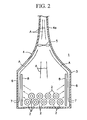
- FIG. 2 shows a modified example of the apparatus shown in FIG. 1 as another embodiment of the present invention.
- This example has a similar configuration to FIG. 1 in which a radiant heat-receiving panel 8 that is adapted to enable efficient absorption of radiant heat is disposed on an inner side of each side wall 6 of the building 2 of the coil yard 1 with a predetermined space between the surface of each side wall 6, for example, a space from several centimeters to ten centimeters, and is disposed to cover the interval from the position that covers an inner side of the intake duct 7 provided on a lower end portion of each side wall 6 to an upper end portion of each side wall 6.
- the panels 8 are mounted on the corresponding side walls 6 with a fixing member (not shown).
- Each radiant heat-receiving panel 8 may be formed for example with a surface coating displaying a high absorption rate for ultraviolet-band wavelengths on a porous aluminum board.
- the radiant heat-receiving panel 8 may also be mounted at a predetermined interval on an inner side of a door of the import conveying port and the export conveying port of the building 3 of the coil yard 1.
- Other aspects of the configuration are the same as those shown in FIG. 1 and the same reference numerals are assigned to the same members.
- a hot-rolled coil 2 when a hot-rolled coil 2 is manufactured by a hot-rolling process causing introduction of heat from hot-rolling equipment (not shown) and is imported by an import conveying port (not shown) into a building 3 of a coil yard 1 to be temporarily accumulated and stored until transfer to a subsequent processing step, air in the building 3 is heated by convection heat from each hot-rolled coil 2. Furthermore, radiant heat (shown by the broken line in the figure, same in the figures hereafter) emitted from each hot-rolled coil 2 in the coil yard building 3 is efficiently absorbed by each radiant heat-receiving panel 8 provided on an inner side of each side wall 6 and thereby heats each radiant heat-receiving panel 8.
- each radiant heat-receiving panel 8 is disposed on an inner side of the intake duct 7 provided on a lower end portion of each side wall 6 of the coil yard building 3. Therefore low-temperature external air introduced into the building 3 through each intake duct 7 is efficiently heated by convection heat from each radiant heat-receiving panel 8 and the resulting an ascending airflow towards the ceiling portion through the space with the side wall 6 corresponding to each radiant heat-receiving panel 8 is produced by buoyancy.
- the present embodiment also enables the production of an ascending airflow ascending in the building 3 towards the chimney 4 of the ceiling portion and passing through the cylindrical portion 4a due to air heated by the heat source of the heat retained in hot-rolled coils 1 in the building 3 of the coil yard 1.
- power generation is performed by driving a power generating turbine 5. Therefore the same effect as the embodiment shown in FIG. 1 is enabled.
- each radiant heat-receiving panel 8 disposed on an inner side of each side wall 6 is heated by absorption of radiant heat from the hot-rolled coils 2 to thereby produce convection heating into the air from each radiant heat-receiving panel 8 that mainly heats the air in the building 3. Therefore the region in which an ascending airflow is produced within the building 3 can be restricted to a region in proximity to each side wall 6. Consequently, it is possible to suppress a risk of the ascending airflow of heated air coming into contact with apparatuses (not shown) that are disposed in proximity to a central portion of the building 3.
- FIG. 3 shows a modified example of the apparatus shown in FIG. 1 as yet another embodiment of the present invention.
- This example has a similar configuration to FIG. 1 in that a radiant heat-receiving panel 8, that is the same as the radiant heat-receiving panel 8 shown in FIG. 2 , is disposed at a position that does not cause interference with the stored hot-rolled coils 2 or when the hot-rolled coils 2 are conveyed in an upper portion of the building 3 of the coil yard 1 in a direction that does not impede the ascending airflow of air produced inside the building 3, for example, in a vertical direction, and are mounted at a predetermined position on the chimney 4 or a predetermined position in the building 3 using a fixing member (not shown).
- a hot-rolled coil 2 that is manufactured by a hot-rolling process causing introduction of heat from hot-rolling equipment (not shown) is imported by an import conveying port (not shown) into a building 3 of the coil yard 1, and is temporarily accumulated and stored until transfer to a subsequent processing step, air in the building 3 is heated by convection heat from each hot-rolled coil 2.
- radiant heat emitted from each hot-rolled coil 2 in the coil yard building 3 is efficiently absorbed by each radiant heat-receiving panel 8 and thereby heats each radiant heat-receiving panel 8. Consequently the air present in proximity to that surface is heated by convection heat from the radiant heat-receiving panels 8.
- the present embodiment also enables the production of an ascending airflow ascending in the building 3 towards the chimney 4 of the ceiling portion and passing through the cylindrical portion 4a as a result of air heated using the heat source of the heat retained in hot-rolled coils 2 in the building 3 of the coil yard 1 to thereby execute power generation by driving a power generating turbine 5.
- the same effect as the embodiment shown in FIG. 1 is enabled.
- the presence of the radiant heat-receiving panel 8 enables more efficient heating of air than the embodiment shown in FIG. 1 , and increases the strength of the resulting ascending airflow, to thereby increase the power generation amount.
- FIG. 4 shows a modified example of the apparatus shown in FIG. 1 as yet a further embodiment of the present invention.
- This example has a similar configuration to FIG. 1 in that a gridiron type member 9 is provided on a floor portion of the building 3 of the coil yard 1 and the hot-rolled coils 2 that are imported into the coil yard 1 are placed on an upper side of the gridiron type member 9 to thereby enable flow of air from below each hot-rolled coil 2 through the lower side of the gridiron type member 9.
- the gridiron type member 9 may be composed of any material as long as it can withstand the weight of the hot-rolled coils 2 and the temperature of the hot-rolled coils 2 immediately after being imported into the coil yard 1.
- a hot-rolled coil 2 that is manufactured by a hot-rolling process by introduction of heat from hot-rolling equipment (not shown) is imported by an import conveying port (not shown) into the building 3 of the coil yard 1, and is temporarily accumulated and stored until transfer to a subsequent processing step, air in the building 3 is heated by convection heat from each hot-rolled coil 2.
- air in the building 3 is heated by convection heat from each hot-rolled coil 2.
- low-temperature external air which is drawn in from an external portion through the intake duct 7 provided at a lower end portion of the three side walls of the building 3 is introduced from below to each hot-rolled coil 2 through the lower side of the gridiron type member 9.
- the present embodiment also enables the production of an ascending airflow ascending in the building 3 as a result of air heated using the heat source of the heat retained in hot-rolled coils 2 in the building 3 of the coil yard 1 to thereby execute power generation by driving the power generating turbine 5 provided in the cylindrical portion 4a of the chimney 4 in the ceiling portion.
- the power generation amount can be increased in comparison with the embodiment shown in FIG. 1 .
- FIG. 5 shows a modified example of the apparatus shown in FIG. 1 as yet a further embodiment of the present invention.
- This example has a similar configuration to FIG. 1 in that an insulating member 10 having resistant properties to high temperatures, for example, an insulating member 10 such as a heat-resistant brick is arranged in the inner bottom portion of the building 3 of the coil yard 1, and from the inner bottom portion of the building 3 is formed an insulating structure to thereby enable suppression of the dissipation of heat from the bottom of the building into the ground surface.
- an insulating member 10 having resistant properties to high temperatures for example, an insulating member 10 such as a heat-resistant brick is arranged in the inner bottom portion of the building 3 of the coil yard 1, and from the inner bottom portion of the building 3 is formed an insulating structure to thereby enable suppression of the dissipation of heat from the bottom of the building into the ground surface.
- a hot-rolled coil 2 that is manufactured by a hot-rolling process by introduction of heat from hot-rolling equipment (not shown) is imported by an import conveying port (not shown) into the building 3 of the coil yard 1, and is temporarily accumulated and stored until transfer to a subsequent processing step, air in the building 3 is heated by convection heat from each hot-rolled coil 2.
- the insulating member 10 is arranged in the inner bottom portion of the coil yard 1, even when the inner bottom portion of the building 3 is heated by the conduction heat or the radiant heat of the hot-rolled coils 2, that heat can be prevented from dissipating into the ground surface below the building 3.
- the present embodiment also enables the production of an ascending airflow ascending in the building 3 as a result of air heated using the heat source of the heat retained in hot-rolled coils 2 in the building 3 of the coil yard 1 to thereby execute power generation by driving the power generating turbine 5 provided in the cylindrical portion 4a of the chimney 4 in the ceiling portion.
- the power generation amount can be increased in comparison with the embodiment shown in FIG. 1 .
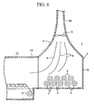
- FIG. 6 shows an applied example of the apparatus shown in FIG. 1 as yet a further embodiment of the present invention.
- This example has a similar configuration to FIG. 1 in that a chimney 4 is provided in a ceiling portion of the building 3 of the coil yard 1 and the power generating turbine 5 is provided in the cylindrical portion 4a of the chimney 4.
- One side portion which forms an import conveying port side in the building 3 of the coil yard 1 communicates with and is connected to an end portion on the extraction side for hot-rolled coils 2 in the building 12 for hot-rolling equipment 11 in which the hot-rolled coils 2 are manufactured using hot-rolling processes in which heat is introduced.
- the building 3 of the coil yard 1 is integrated with the building 12 of the hot-rolling equipment.
- a hot-rolled coil 2 that is manufactured by hot-rolling equipment 11 is imported into the building 3 of the coil yard 1, and is temporarily accumulated and stored until transfer to a subsequent processing step, in the same manner as the apparatus shown in FIG. 1 , air in the building 3 is mainly heated and undergoes a reduction in density due to convection heating from heat retained in each hot-rolled coil 2 in the coil yard building 3, and the resulting buoyancy produces an ascending airflow that rises in the building 3 towards the chimney 4 in the ceiling portion and passes through an inner portion of the cylindrical portion 4a.
- the present embodiment also enables the production of an ascending airflow ascending in the building 3 towards the chimney 4 in the ceiling portion and passing through the cylindrical portion 4a as a result of air heated using the heat source of the heat retained in hot-rolled coils 2 in the building 3 of the coil yard 1 to thereby execute power generation by driving the power generating turbine 5 provided in the cylindrical portion 4a of the chimney 4 in the ceiling portion.
- the same effect as the embodiment shown in FIG. 1 is enabled.
- the strength of the draft of the ascending airflow that drives the power generating turbine 5 can be increased, the power generation amount can be increased.
- FIG. 7 and FIG. 8 show a modified example of the apparatus shown in FIG. 6 as yet a further embodiment of the present invention.
- This example has a similar configuration to FIG. 6 in that a radiant heat-receiving panel 8, that is the same as that shown in FIG. 2 , is provided on an inner side of the three side walls 6 excluding the connection position with the building 12 of the heat-rolling equipment 11 and the building 3 of the coil yard 1.
- the present embodiment also obtains the same effect as the embodiment shown in FIG. 6 .
- the radiant heat-receiving panels 8 that are disposed on an inner side of the three side walls 6 are heated by absorption of the radiant heat of the hot-rolled coils 2 to thereby enable production of convection heat into air from each radiant heat-receiving panel 8.
- the power generation amount can be further increased.
- the present invention is not limited to the configuration in each of the above embodiments, and to the extent that the power generating turbine 5 can be driven by the ascending airflow passing through the cylindrical portion 4a of the chimney 4, the height at which the power generating turbine 5 is disposed in the cylindrical portion 4a of the chimney 4 may be suitably varied.
- a radiant heat-receiving panel 8 may be disposed in the same manner as shown in FIG. 3 at a position that does not cause interference with the stored hot-rolled coils 2 or when the hot-rolled coils 2 are conveyed in an upper portion of the building 3 of the coil yard 1. In this manner, since the air in the building 3 is more efficiently heated and the strength of the ascending airflow in the building 3 of the coil yard 1 is further increased, the power generation amount can be further increased.
- an gridiron type member 9 that is the same as that shown in FIG. 4 may be provided on the floor portion of the building 3 of the coil yard 1. In this manner, it is possible to pass air through the lower side of each hot-rolled coils 2 and to promote transmission of convection heat into the air in the building 3 resulting from heat retained in each hot-rolled coils 2. Thus air in the building 3 is more efficiently heated, the strength of the ascending airflow produced in the building 3 of the coil yard 1 can be further strengthened thereby enabling a further increase to the power generation amount.
- an insulating member 10 having high-temperature resistant properties in the same manner as that shown in FIG. 5 can be arranged on the inner bottom portion of the building 3 of the coil yard 1.
- the available heat amount for heating the air in the building 3 can be increased and the heating efficiency for air in the building 3 can be increased.
- a further increase in the power generation amount is enabled as a result of increasing the strength of the ascending airflow that is produced in the building 3.
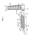
- FIG. 9 shows another embodiment of a high-temperature heat radiating body storage yard power generation apparatus according to the present invention which is applied to a coil yard 1 which acts as a high-temperature heat radiator storage yard for the temporary storage of a hot-rolled coil 102 which is an intermediate iron and steel product acting as a high-temperature heat radiator that is manufactured using the hot-rolling equipment of an integrated iron and steel mill or the like, and the configuration thereof will be described below.
- An air discharge tower 104 which is provided with a funnel-shaped air passage 104a extending vertically in predetermined dimensions within the tower at a predetermined allotment separated by a predetermined distance from a coil yard building 103 on an outer side of the coil yard building 103 configured for temporary storage of hot-rolled coils 102 manufactured by introducing heat by hot-rolling equipment prior to transfer to a subsequent processing step is constructed separately to a building 103.
- a discharge port 105 is provided in proximity to an upper portion of a side wall of the building 103 and a connecting duct 106 connects a lower position of the funnel-shaped air passage 104a of the air discharge tower 104 with the discharge port 105. Furthermore a power generating turbine 107 is disposed at a predetermined position in a vertical direction of the air discharge tower 104.
- an intake duct 108 is provided in a predetermined position on each side wall except for one side wall in which the discharge port 105 provides for connecting the connecting duct 106.
- an import conveying port and an export conveying port for hot-rolled coils 102 in the coil yard building 103 are provided in a predetermined side wall of the coil yard building 103 and an opening and closing door may be provided.
- an intake duct that is the same as the intake duct 108 may also be provided in the lower portion of the door of the import conveying port and the export conveying port.
- a conveying means (not shown) for the hot-rolled coils 102 may be provided in the building 103.
- the entire peripheral surface of the connecting duct 106 is provided with an insulating member (not shown) and air 109 discharged from the discharge port 105 of the building 103 is introduced into the air discharge tower 104 while preventing a reduction in temperature, and thereby maintains the temperature of the air 109 passing through the inner portion of the air discharge tower 104 as much as possible.
- Reference numeral 104b denotes a support structure of the air discharge tower 104.
- the hot-rolled coil 102 that is manufactured by a hot-rolling process by introduction of heat by hot-rolling equipment (not shown) is imported by an import conveying port (not shown) into the building 103 of the coil yard 101 provided with a high-temperature heat radiating body storage yard power generation apparatus as described above, and is temporarily accumulated and stored until transfer to a subsequent processing step.
- the heat retained in each hot-rolled coil 102 in the coil yard building 103 undergoes heat transfer into the air 109 in the building 103 mainly due to convection heating, and thereby the air 109 in the building 103 is heated.
- the heated air 109 becomes buoyant due to a reduction in density, rises in the building 103 towards a discharge port 105 provided in an upper portion in proximity to one side wall of the building 103, is introduced from the discharge port 105 through the connecting duct 106 into a lower portion of the funnel-shaped air passage 104a of the air discharge tower 104 and rises through the funnel-shaped air passage 104a of the air discharge tower 104 to be released in an external portion by an upper end discharge port of the air discharge tower 104.
- low-temperature external air is introduced into the building 103 through each air intake duct 108 that is provided in the side walls of the building 103 due to the air 109 heated inside the building 103 being introduced from the discharge port 105 through the connecting duct 106 into the air discharge tower 104.
- a flow of air 109 is produced in the building 103 that passes through the building 103 from each intake port 108 in succession towards the discharge port 105 and the air 109 is successively heated by convection heating by the heat retained in the hot-rolled coils 102 in the period in which the air 109 passes through the building 103.
- air 109 can be efficiently heated by heat retained in the hot-rolled coils 102 in a building 103 of a coil yard 101 that has a high heat density since high-temperature hot-rolled coils 102 immediately after manufacturing processes are accumulated and stored. Furthermore air 109 that is heated efficiently to produce a buoyancy by heat retained in the hot-rolled coils 102 passes from the discharge port 105 of the building 103 through connecting duct 106 and is introduced into an external air discharge tower 104 to thereby efficiently produce an ascending airflow in the air discharge tower 104. In this manner, efficient power generation can be executed by efficient driving of the power generating turbine 107 provided in the air discharge tower 104.
- the air discharge tower 104 Since the air discharge tower 104 is provided on a separate allotment to the building 103 of the coil yard 101, construction work for the air discharge tower 104 requiring a number of days to construct the power generation apparatus for a high-temperature heat radiator storage yard according to the present invention can be performed without having any effect on the coil yard 101. Furthermore the work associated with providing the discharge port 105 or the intake duct 108 in the side wall of the building 103 of the coil yard can be executed without problems. Thus when the high-temperature heat radiator storage yard generating apparatus according to the present invention is provided in a coil yard 101 in an existing high-temperature heat radiator storage yard, a risk of impediment to the operation of the existing high-temperature heat radiator storage yard can be avoided and its operation can be continued.
- FIG. 10 shows a modified example of the apparatus shown in FIG. 9 as yet a further embodiment of the present invention.
- This example has a similar configuration to FIG. 9 in that the other side portion facing one side wall on which the discharge port 105 is provided in the building 103 of the coil yard 101 communicates with and is connected to the end portion on the extraction side for hot-rolled coils 102 in the building 111 of the hot-rolling equipment 110 that manufactures the hot-rolled coils 102 using a hot-rolling process by introduction of heat.
- the building 111 of the hot-rolling equipment 110 and the building 103 of the coil yard 101 are integrated.
- the intake duct 108 on the side walls is omitted to thereby enable air to be drawn from the building 111 of the hot-rolling equipment 110.
- Other aspects of the configuration are the same as those shown in FIG. 9 and the same reference numerals are assigned to the same members.
- the hot-rolled coils 102 manufactured by the hot-rolling equipment 110 are imported into the building 103 of the coil yard 101 and temporarily stored until transfer to a subsequent process, in the same manner as the embodiment shown in FIG. 9 , air in the building 103 is heated mainly by convection heating by heat retained in each hot-rolled coil 102 in the coil yard building 103.
- the air 109 that is heated to a reduced density and becomes buoyant is introduced from the discharge port 105 of the building 103 through the connecting duct 106 into the discharge tower 104 to thereby produce an ascending airflow in the discharge tower 104.
- the temperature of the air 109 that is introduced from the discharge port 105 of the building 103 of the coil yard 101 through the connecting duct 106 into the discharge tower 104 can be further increased, the wind speed of the ascending airflow produced by the buoyancy of heated air in the discharge tower 104 can be increased and the power generation amount of the power generating turbine 107 can be increased.
- FIG. 11 shows a modified example of the apparatus shown in FIG. 9 as yet a further embodiment of the present invention.
- This example has a similar configuration to FIG. 9 in that a plurality of water spraying nozzles 112 is provided on the ceiling portion in the building 103 of the coil yard 101 corresponding to the disposition of the hot-rolled coils 102 disposed in the building 103.
- a water supply line 114 introducing water 115 from a water pump 113 in an external portion of the building is connected to each water spraying nozzle 112 and water 115 supplied from the water pump 113 through the water supply line 114 can be sprayed as a mist or as a shower from each water spraying nozzle 112 on the hot-rolled coils 102 that are stored in the building 103.
- a water supply valve 116 corresponding to each individual water spraying nozzle 112 is provided in the water supply line 114 connected to each water spraying nozzle 112 to thereby enable individual switching between spraying of water 115 from each water spraying nozzle 112 and stopping of spraying.
- selective spraying of water 115 onto those groups of hot-rolled coils 102 of the respective hot-rolled coils 102 stored in the building 103 that are at a relatively high temperature is enabled by opening only the water supply valves 116 corresponding to the water spraying nozzle 112 that are disposed above a group of the relatively high-temperature hot-rolled coils 102 that have not spent much time in the yard after importing into the building 103.
- the water 115 that is supplied to each water spraying nozzle 112 by the water pump 113 may be, for example, cold water that is heated (warmed) after being supplied for use in a cooling process during hot rolling by the hot-rolling equipment that manufactures the hot-rolled coils 102.
- cold water that is heated (warmed) after being supplied for use in a cooling process during hot rolling by the hot-rolling equipment that manufactures the hot-rolled coils 102.
- air heated in the building 103 of the coil yard 101 that stores the hot-rolled coils 102 by convection heating by heat retained in each stored hot-rolled coil 102 is introduced from the discharge port 105 of the building 103 through the connecting duct 106 into the discharge tower 104.
- the water supply valve 116 is opened corresponding to each water spraying nozzle 112 disposed above a group of the relatively high-temperature hot-rolled coils 102
- the water 115 that is supplied from the water pump 113 through the water supply line 114 is sprayed as a mist or as a shower towards the group of the relatively high-temperature hot-rolled coils 102.
- a part of the water drops in the water 115 that is sprayed towards a group of the relatively high-temperature hot-rolled coils 102 are heated and evaporated midway during descending by contact with the air 9 that is heated by the convection heat of heat retained in the hot-rolled coils 102.
- the remaining water drops that are sprayed fall onto the group of the relatively high-temperature hot-rolled coils 102, and the water drops that come into contact with each hot-rolled coil 102 are directly heated and evaporate due to heat retained in each hot-rolled coil 102.
- each water spraying nozzle 112 When the water 115 that is sprayed onto a group of the relatively high-temperature hot-rolled coils 102 by each water spraying nozzle 112 is heated directly by heat retained in the group of the hot-rolled coils 102, or indirectly by the heated air 109, and evaporates to form steam 117, the volume expands by one thousand and several hundred times.
- the amount of heated gas is greatly increased by the addition of the large amount of steam 117 produced by evaporating water 115 sprayed from each water spraying nozzle 112 into the air 109 that is heated by the convection heating with the hot-rolled coils 102 in the building 103.
- the large amount of steam 117 is produced by evaporation of the water 115 sprayed from the water spraying nozzles 112 using heat retained in the hot-rolled coils 102.
- the large amount of steam 117 is also introduced into the discharge tower 104 to thereby enable a radical increase in the wind speed of the air ascending through the discharge tower 104. In this manner, the energy that is recoverable by the power generating turbine 107 can be increased and the output of the power generating turbine 107 can be markedly increased.
- the earliest imported coil of the hot-rolled coils 102 that are already stored in the coil yard 101 that is to say, the hot-rolled coil 102 with the lowest temperature as a result of dissipating heat for the longest period is exported in that sequence through the export conveying port (not shown).
- the water supply valve 116 of those water supply valves 116 provided for each of the water spraying nozzles 112, that corresponds to the water spraying nozzle 112 positioned above the newly imported hot-rolled coil 102 is opened, and a spray of water may be commenced onto the hot-rolled coil 102 having a large heat retention amount that has been newly imported into the building 103.
- the water supply valve 116 is stopped that corresponds to the water spraying nozzle 112 positioned above the hot-rolled coil 102, of those hot-rolled coils 102 that are already stored in the coil yard 101, with a temperature that has fallen to a level at which the sprayed water 115 cannot be sufficiently evaporated.
- the present invention is not limited to each of the embodiments above, and the discharge port 105 of the building 103 of the coil yard 101 may be provided at a predetermined position on the ceiling portion of the building 103 rather than at a position proximate to an upper portion of the side wall, and the discharge port 105 provided on the ceiling portion of the building 103 may be connected through the connecting duct 106 with the lower portion of the discharge tower 104.
- the height at which the power generating turbine 107 is disposed in the discharge tower 104 may be suitably varied.
- the power generating turbine 107 may be provided in the connecting duct 106.
- a cylindrical passage corresponding to the diameter of the power generating turbine 107 may be formed on the connecting duct 106, and the power generating turbine 107 may be mounted in a portion of the cylindrical passage.
- connection positions corresponding to the funnel in the end portion towards the lower flow in the connecting duct mounted in the discharge port 105 of the building that houses the coil yard 101 may be suitably provided so that the discharge air flowing through the funnel does not undergo reverse flow toward the building 103 of the coil yard 101.
- water supply valves 116 that can switch independently between water spraying from each water spraying nozzle 112 and terminating spraying are respectively provided for each water spraying nozzle 112 provided in the ceiling portion in the building 103 of the coil yard 101, one water supply valve 116 may be provided for each of a plurality of water spraying nozzles 112 provided within a certain range in the building 103. Furthermore when the position into which the newly manufactured hot-rolled coil 102 with a large heat amount is determined in the building 103 of the coil yard 101, a water spraying nozzle 112 may be provided only above the position to which the newly manufactured hot-rolled coil 102 with a large heat amount is imported.
- the configuration of the embodiment above may be modified by a configuration in which a member is provided to increase the heating efficiency of air in the building 103 using heat retained in the hot-rolled coil 102 stored in the building 103.
- a gridiron type member (not shown) to allow passage of air to a lower side of each hot-rolled coil 102 is provided on a floor portion of the building 103 of the coil yard 101 and the hot-rolled coils 102 imported into the coil yard 101 are placed on an upper side of the gridiron type member.
- the configuration may be modified by a configuration in which an insulating member having high-temperature resistant properties is arranged to suppress dissipation of heat to the ground surface from the bottom portion of the building 103 of the coil yard 101.
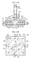
- FIG. 12A and 12B to FIG. 14A and 14B show yet a further embodiment of the present invention applied to a coil yard 201 that is an example of a high-temperature heat radiator storage yard for temporary storage of a hot-rolled coil 202 which is an intermediate iron and steel product acting as a high-temperature heat radiator that is manufactured using the hot-rolling equipment of an integrated iron and steel mill or the like, and the configuration thereof will be described below.
- a power generating turbine 205 is provided at a predetermined position in a vertical direction in the air discharge tower 204 so that the ceiling surface of the coil yard building 203 is smoothly connected to the inner side of the air discharge tower 204 by forming a lower end portion 204a of the air discharge tower 204 in the shape of a flare.
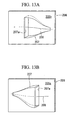
- air ducts 207 enabling inflow of air (external air) 208 in a horizontal direction along an inner face of each side wall 206 are provided at a plurality of predetermined positions on a lower portion on the four side walls 206 forming the peripheral walls of the building 203 so that the inflow direction of air 208 inflowing in a horizontal direction into the building 203 through each air duct 207 meets at either one of a clockwise or a counterclockwise air circulation direction when viewed on a plane, for example, as shown in FIG. 12B , all inflow directions of the air 208 passing through each air duct 207 meet in a clockwise direction when viewed on a plane.
- the air duct 7 is formed as an NACA-type duct in which an opening 207a connected into the building 203 and extending with a predetermined dimension in a horizontal direction is configured as a rectangular opening 207a extending vertically along an inner surface of the building side wall 206.
- the air duct 207 may be formed as a two-dimensional lamp-type duct in which the opening 207a connected into the building 203 and extending with a predetermined dimension in a horizontal direction is configured as a rectangular opening 207a extending vertically along an inner surface of the building side wall 206.
- the flow of the air 208 in a horizontal direction along the inner wall 206a of the side wall 206 can be efficiently produced inside the building 203 by the input of the air 208 into the building 203 from an external portion of the building through the air duct 207.
- the reference numeral 206b shown in FIG. 13A and FIG. 13B , and FIG. 14A and FIG. 14B denotes the outer surface of the side wall 206.
- the size of the air duct 207 may be suitably set considering the scale of the coil yard building 203, the height of the discharge tower 204 and the number of hot-rolled coils 202 normally stored in the building 203 so that the inflow air amount is balanced by the air discharge amount from the building 203 to an external portion when the air in the building 203 is heated by the conductive heating of heat retained in the hot-rolled coils 202 stored in the building 203, rises in the air discharge tower 204 and is discharged to an external portion from an upper end port of the discharge tower 204.
- the number of air ducts 207 may also be suitably modified so that the air inflow amount balances the air discharge amount from within the building 203 to an external portion.
- the import conveying port and the export conveying port for hot-rolled coils 202 in the coil yard building 203 may be provided in a predetermined side wall 206 of the coil yard building 203 and may be provided with an opening and closing door. Further, an air duct that is the same as the air duct 207 may also be provided in a lower portion of the door of the import conveying port and the export conveying port.
- a conveying means (not shown) for the hot-rolled coils 202 may be provided in the building 203.
- the hot-rolled coil 202 that is manufactured by a hot-rolling process causing introduction of heat from hot-rolling equipment (not shown) is imported by an import conveying port (not shown) into the building 203 of the coil yard 201 provided with a high-temperature heat radiator storage yard generating apparatus as described above, and is temporarily accumulated and stored until transfer to a subsequent processing step.
- the heat retained in each hot-rolled coil 202 in the coil yard building 203 undergoes heat transfer into the air 208 in the building 203 mainly due to convection heating, and thereby the air 208 in the building 203 is heated.
- the heated air 208 undergoes a reduction in density and displaces towards the air discharge tower 204 in the ceiling portion by ascending in the building 203 due to the resulting buoyancy. After passing through the air discharge tower 204, the heated air 208 is released into an external portion by an upper end discharge port.
- the time required to reach the air discharge tower 204 provided near to the center of the ceiling portion of the building 203 is lengthened. In this manner, since the heat exchange time for convection heat with each hot-rolled coil 202 spread out on the large surface area in the coil yard building 203 is increased, the temperature increase in the air 208 that is heated by convection heating from each hot-rolled coil 202 is further increased.
- the flow amount of air 208 can be increased by buoyant air 208 in the building 203 being introduced into the air discharge tower 204 and ascending therein. Consequently, driving of the power generating turbine 205 provided in the air discharge turbine 204 can be performed by the ascending airflow of air 208 that displays an increased flow amount to thereby execute power generation.
- a revolving flow of the air 208 that displays low vertical components can be produced in the building 203 of the coil yard 201 that displays an elevated heat density by accumulating and storing the hot-rolled coils 202 that have a high temperature immediately after manufacture. Furthermore the heat exchange time of each hot-rolled coil 202 with the air 208 in the building 203 can be increased.
- the air 208 in the building 203 is heated more efficiently and air heated to produce a higher buoyancy can be introduced into the air discharge tower 204. Consequently, the airflow amount ascending in an inner portion of the air discharge tower 204 can be increased, the energy that is recoverable by the power generating turbine 205 can be increased, and therefore the output of the power generating turbine 205 can be increased.
- FIG. 15A and FIG. 15B shows a modified example of the apparatus shown in FIG. 12A and FIG. 12B to FIG. 14A to FIG. 14B as yet another embodiment of the present invention.
- a plurality of water spraying nozzles 209 corresponding to the disposition of the hot-rolled coils 202 disposed in the building 203 is provided on a ceiling portion in the building 203.
- a water supply line 211 introducing water 212 from a water pump 210 in an external portion of the building is respectively connected to each water spraying nozzle 209, and the water 212 supplied through the water supply line 211 from the water pump 210 is sprayed as a mist or as a shower onto the hot-rolled coils 202 stored in the building 203 from each water spraying nozzle 209.
- a water supply valve 213 corresponding to each individual water spraying nozzle 209 is provided on the water supply line 211 connected to each water spraying nozzle 209 to thereby enable individual switching between spraying of water 212 from each water spraying nozzle 209, and stopping of spraying.
- selective spraying of water 212 onto those groups of hot-rolled coils 202 of the respective hot-rolled coils 202 stored in the building 203 that are at a relatively high temperature is enabled by opening only the water supply valves 213 corresponding to the water spraying nozzle 209 that is disposed above a group of the relatively high-temperature hot-rolled coils 202 that have not spent much time in the yard after importing into the building 203.
- the water 212 that is supplied to each water spraying nozzle 209 by the water pump 210 may be, for example, cold water that is heated (warmed) after being supplied for use in a cooling process during hot rolling by the hot-rolling equipment (not shown) that manufactures the hot-rolled coils 202.
- the energy corresponds to the sensible heat required to heat the water 212 to an evaporation temperature can be reduced when the water 212 that is sprayed from the water spraying nozzles 209 is evaporated by heat retained in the hot-rolled coils 202, a useful configuration is enabled in which the production efficiency for steam 214 by the heat retained in the hot-rolled coils 202 is increased.
- the air 208 flows into the building 203 though each air duct 207 provided in the four side walls 106 of the building 203 of the coil yard 201 that stores the hot-rolled coils 202 to thereby produce a flow of air 208 that revolves in the building 203 while displaying low levels of vertical components.
- each water spraying nozzle 209 When the water 212 sprayed onto a group of the relatively high-temperature hot-rolled coils 202 by each water spraying nozzle 209 is heated directly by heat retained in the group of the hot-rolled coils 202, or indirectly by the heated air 208, and evaporates to form steam 214, the volume expands by one thousand and several hundred times.
- the amount of heated gases in the building 203 can be greatly increased by adding the large amount of the steam 214 produced by evaporating the water 212 sprayed from each water spraying nozzle 209 into the air 208 that is heated by the convection heating with the hot-rolled coils 202.
- the steam 214 mixed with a revolving flow of the heated air 208 displaces towards the air discharge tower 204 provided near to the center of a ceiling portion of the building 203 and passes through an inner portion of the air discharge tower 204, and then is discharged to an external portion through an upper end discharge port, the speed of the airflow ascending in the air discharge tower 204 can be increased. Therefore the power generating turbine 205 provided in the discharge tower 204 is driven by the accelerated ascending airflow to execute wind-power generation.
- a large amount of the steam 214 is produced by evaporation of the water 212 sprayed from the water spraying nozzles 209 using the heat retained in the hot-rolled coils 202.
- the large amount of the steam 214 is introduced into the discharge tower 204 to thereby enable a radical increase in the wind speed of the air ascending through the discharge tower 204. In this manner, the energy that is recoverable by the power generating turbine 205 can be increased and the output of the power generating turbine 205 can be markedly increased.
- the water supply valve 213 of the water supply valves 213 provided for each of the water spraying nozzles 209 that corresponds to the water spraying nozzle 209 positioned above the newly imported hot-rolled coil 202 is opened, and a spray of water may be commenced onto the hot-rolled coil 202 that has a large heat retention amount and has been newly imported into the building 203.
- the water supply valve 213 that corresponds to the water spraying nozzle 209 positioned above the hot-rolled coil 202 of the hot-rolled coils 202 that are already stored in the coil yard 201 that has a temperature that has fallen to a level at which the sprayed water 212 cannot be sufficiently evaporated is closed.
- the spraying of water 212 from the water spraying nozzle 209 may be stopped.
- the present invention is not limited to each of the embodiments above, to the extent that the power generating turbine 205 are driven by the ascending airflow passing through the inner portion of the discharge tower 204, the height and position of the power generating turbine 205 in the discharge tower 204 may be suitably varied.
- the air duct 207 provided in the side wall 206 of the building 203 of the coil yard 201 was exemplified by an NACA-type duct in FIG. 13A and FIG. 13B , and by a two-dimensional lamp-type duct in FIG. 14A and FIG. 14B
- a configuration of the air duct 207 other than that shown in the figures may be used to the extent that a flow of the air 208 from an external portion of the building 203 passes through the air duct 207 and flows into an inner portion of the building 203 to thereby create a flow of the air 208 in a horizontal direction along the inner surface 206a of the side wall 206 of the building 203.
- each of the air ducts 207 provided in the side wall 206 of the building 203 may be suitably varied in response to the shape and the like of the building 203.
- the water spraying valve 213 that individually switches between spraying and stopping spraying of the water 212 from each water spraying nozzle 209 is respectively disposed in each water spraying nozzle 209 provided on a ceiling portion in the building 203 of the coil yard 201.
- one water spraying valve 213 may be provided for a plurality of water spraying nozzles 209 provided in a certain range in the building 203.
- the water spraying nozzle 209 may be only provided above the position to which newly manufactured hot-rolled coil 202 having a large heat retention amount is conveyed.
- a configuration may be added in which a member is provided to increase the heating efficiency of the air 208 in the building 203 using heat retained in the hot-rolled coil 202 stored in the building 203.
- a gridiron type member (not shown) to allow passage of the air 208 to a lower side of each hot-rolled coil 202 is provided on a floor portion of the building 203 of the coil yard 201 and the hot-rolled coils 202 imported into the coil yard 201 are placed on an upper side of the gridiron type member.
- a configuration may be added in which an insulating member having high-temperature resistant properties is arranged on an inner bottom portion of the building 203 of the coil yard 201 to suppress dissipation of heat to the ground surface from the bottom portion of the building 203 of the coil yard 201.
- FIG. 16 shows yet a further embodiment of the present invention applied to a coil yard 301 which acts as a high-temperature heat radiator storage yard for temporary storage of a hot-rolled coil 302 which is an intermediate iron and steel product acting as a high-temperature heat radiator that is manufactured using the hot-rolling equipment of an integrated iron and steel mill or the like, and the configuration thereof will be described below.
- a power generating turbine 305 is provided at a predetermined position in a vertical direction in the air discharge tower 304 so that the ceiling surface of the coil yard building 303 is smoothly connected to the inner side of the air discharge tower 304 by forming a lower end portion 304a of the air discharge tower 304 in the shape of a flare.
- An intake duct 307 is provided in the lower end portion in the four side walls 306 of the building 303.
- a plurality of water spraying nozzles 308 corresponding to the storage position of the hot-rolled coils 302 disposed in the building 303 is provided on a ceiling portion in the building 303. Furthermore a water supply line 310 introducing water 311 from a water pump 309 in an external portion of the building is respectively connected to each of the water spraying nozzles 308, and the water 311 supplied through the water supply line 310 from the water pump 309 is sprayed from each water spraying nozzle 308 as a mist or as a shower onto the hot-rolled coils 302 stored in the building 303.
- a water supply valve 312 corresponding to each individual water spraying nozzle 308 is provided on the water supply line 310 connected to each of the water spraying nozzles 308 to thereby enable individual switching between spraying of water 311 from each water spraying nozzle 308, and stopping of spraying.
- selective spraying of water 311 onto those groups of hot-rolled coils 302 of the respective relatively high-temperature hot-rolled coils 302 stored in the building 303 is enabled by opening only the water supply valves 312 corresponding to the water spraying nozzle 308 disposed above a group of the relatively high-temperature hot-rolled coils 302 that have not spent much time in the yard after importing into the building 303.
- the water 311 that is supplied to each water spraying nozzle 308 by the water pump 309 may be, for example, cold water that is heated (warmed) after being supplied for use in a cooling process during hot rolling by the hot-rolling equipment (not shown).
- the energy corresponds to the sensible heat required to heat the water 311 to an evaporation temperature can be reduced when the water 311 that is sprayed from the water spraying nozzles 308 is evaporated by heat retained in the hot-rolled coils 302, a useful configuration is enabled in which the production efficiency of steam by the heat retained in the hot-rolled coils 302 is increased.
- an export conveying port and an import conveying port of the hot-rolled coils 302 in the coil yard building 303 may be provided in a predetermined side wall 306 of the coil yard building 303 and may be provided with an opening and closing door. Furthermore an air intake duct similar to the air intake duct 307 above may be provided in a lower end portion of the door of the export conveying port and the import conveying port.
- a conveying means (not shown) for the hot-rolled coils 302 may be provided in the building 303.
- the disposition of the conveying means (not shown) and each water spraying nozzle 308 and water supply line 310 may be determined to avoid interference.
- the hot-rolled coil 302 that is manufactured by a hot-rolling process by introduction of heat from hot-rolling equipment (not shown) is imported by an import conveying port (not shown) into the building 303 of the coil yard 301 provided with a high-temperature heat radiator storage yard generating apparatus as described above, and is temporarily accumulated and stored until transfer to a subsequent processing step.
- the heat retained in each hot-rolled coil 302 in the coil yard building 303 undergoes heat transfer into the air in the building 303 mainly due to convection heating, and thereby the air in the building 303 is heated.
- the heated air undergoes a reduction in density and displaces towards the discharge tower 304 in the ceiling portion by ascending in the building 303 due to the resulting buoyancy. After passing through the discharge tower 304, the air is released into an external portion through an upper end discharge port.
- the water supply valve 312 is opened corresponding to each water spraying nozzle 308 disposed above a group of the relatively high-temperature hot-rolled coils 302, the water 311 supplied from the water pump 309 through the water supply line 310 is sprayed as a mist or as a shower towards the group of the relatively high-temperature hot-rolled coils 302.
- a part of the water drops in the water 311 sprayed towards a group of the relatively high-temperature hot-rolled coils 302 is heated and evaporated midway during descending by contact with the air that is heated by the convection heat of heat retained in the hot-rolled coils 302.
- the remaining water drops that are sprayed fall onto the group of the relatively high-temperature hot-rolled coils 302, and the water drops that come into contact with each hot-rolled coil 302 are directly heated and evaporate due to heat retained in each hot-rolled coil 302.
- the high-temperature heat radiator storage yard generating apparatus of the present invention air can be more efficiently heated using heat retained in hot-rolled coils 302 in a building 303 of a coil yard 301 that is subjected to an increased heat density by accumulating and storing high-temperature hot-rolled coils 302 immediately after manufacture. Furthermore, since a large amount of steam can be produced by using the heat retained in the hot-rolled coils 302 to evaporate the water 311 sprayed from the water spraying nozzles 308, it is possible to introduce an ascending airflow of the large amount of steam produced in the building 303 into the discharge tower 304.
- the wind speed of the airflow ascending inside the air discharge tower 304 is radically increased in comparison to introduce an ascending airflow which is heated by only the convection heating of the hot-rolled coils 302 in the building 303 to the discharge tower 304.
- the increase in the wind speed of the ascending airflow in the discharge tower 304 increases the energy that is recoverable by the power generating turbine 305 and thus enables a marked increase in the output of the power generating turbine 305.
- the earliest imported coil of the hot-rolled coils 302 that are already stored in the coil yard 301 that is to say, the hot-rolled coil 302 with the lowest temperature as a result of dissipating heat for the longest period is successively exported through the export conveying port (not shown).
- the water supply valve 312, of those water supply valves 312 provided for each of the water spraying nozzles 308, that corresponds to the water spraying nozzle 308 positioned above the newly imported hot-rolled coil 302 is opened, and a spray of water may be commenced onto the hot-rolled coil 302 having a large heat retention amount that has been newly imported into the building 303.
- the water supply valve 312 that corresponds to the water spraying nozzle 308 positioned above the hot-rolled coil 302, of the hot-rolled coils 302 that are already stored in the coil yard 301, with a temperature that has fallen to a level at which the sprayed water 311 cannot be sufficiently evaporated is closed.
- the spraying of water 302 from the water spraying nozzle 308 may be stopped.
- FIG. 17 shows an example of the apparatus shown in FIG. 16 as yet a further embodiment of the present invention.
- a rainwater tank 313 which is provided at a higher position than the position at which the respective water spraying nozzles 308 are disposed on the ceiling portion in the building 303, for example, on an upper side of the roof of the building 303 is connected upstream of the water supply line 310.
- a rainwater recovery mechanism 314 for recovering water falling onto the building 303 is mounted in the rainwater tank 313.
- the rainwater tank 313 may be provided at a position other than the roof of the building 303 of the coil yard 301. Furthermore rainwater from the rainwater recovery mechanism provided on a structural element higher than the building 303 of the coil yard 301 (not shown) may be recovered into the rainwater tank 313 by gravity feeding. Even in the event that there is no rainwater in the rainwater tank 313 due to lack of rainfall, a water supply means such as running water or the like may be provided to the rainwater tank 313 to continue supply of water 311 to the respective water spraying nozzles 308.
- rainwater in the rainwater tank 313 can be supplied by gravity-feed energy as the water 311 for spraying to each water spraying nozzle 308 provided on the ceiling portion of the building 303.
- the energy required to supply water to each water spraying nozzle 308 can be reduced and therefore a reduction is enabled in the energy consumed in recovering as energy the heat retained in the hot-rolled coils 302 stored in the coil yard 301.
- the present invention is not limited to only the above embodiments, and to the extent that the power generating turbine 305 is driven by an ascending airflow passing through an inner portion of the discharge tower 304, the position and height of disposition of the power generating turbine 305 in the discharge tower 304 can be suitably varied.
- the water spraying nozzles 308 are provided across the entire surface of the ceiling portion of the building 303 of the coil yard 301 and switching between spraying or stopping spraying of water 311 from each water spraying nozzle 308 is enabled by the water supply valve 312 provided in each water spraying nozzle 308.
- one water supply valve 312 may be provided for each of a plurality of water spraying nozzles 308 provided within a certain range in the building 303, and switching between spraying and stopping spraying of water 311 from the plurality of water spraying nozzles 308 provided in a certain range in the building 303 may be enabled by operation of the water supply valve 312.
- the water spraying nozzle 308 may be provided only above the position to which the newly manufactured hot-rolled coil 302 with a large heat amount is imported into the building 303.
- Inflow of external air into the building 303 from an external portion of the building 303 may only be allowed through each intake duct 307 provided in the side walls 306 of the building 303 of the coil yard 301, and a reverse-flow prevention damper (not shown) may be provided to prevent gas escaping to an external portion from the internal portion of the building 303.
- the configuration of the embodiment above may be modified by a configuration in which a member is provided to increase the heating efficiency for air in the building 303 using heat retained in the hot-rolled coil 302 stored in the building 303.
- a configuration may be provided in which a radiant heat-receiving panel (not shown) is provided at a position that does not interfere with the water sprayed from the water spraying nozzles 308 in an upper portion of the building 303 of the coil yard 301, or with the conveying of hot-rolled coils 302 or with stored hot-rolled coils 302 or on an inner side of the side wall 306 of the building 303 of the coil yard 301.
- a configuration may be provided in which a gridiron type member (not shown) to allow passage of air to a lower side of each hot-rolled coil 302 is provided on a floor portion of the building 303 of the coil yard 301 and the hot-rolled coils 302 imported into the coil yard 301 are placed on an upper side of the gridiron type member.
- a configuration may be provided in which an insulating member having high-temperature resistant properties is arranged to suppress dissipation of heat to the ground surface from the bottom portion of the building 303 of the coil yard 301.
- All of the embodiments above describe an example of application to a coil yard for temporary storage of a hot-rolled coil 2 that is an intermediate iron and steel product that is manufactured in an integrated iron and steel mill or the like acting as a high-temperature heat radiator manufactured by introduction of heat.
- a storage yard for an intermediate iron and steel products such as a slab yard that temporarily stores steel billet such as a slab or the like manufactured by continuous casting by introduction of heat in an integrated iron and steel mill.
- the high-temperature heat radiator storage yard is adapted for temporary accumulation and storage prior to transfer to a subsequent processing step while dissipating the heat retained in a high-temperature heat radiator manufactured by introduction of heat by various types of equipment, application is possible to any type of high-temperature heat radiating body storage yard.
Landscapes
- Engineering & Computer Science (AREA)
- Chemical & Material Sciences (AREA)
- Combustion & Propulsion (AREA)
- Life Sciences & Earth Sciences (AREA)
- Sustainable Development (AREA)
- Sustainable Energy (AREA)
- Mechanical Engineering (AREA)
- General Engineering & Computer Science (AREA)
- Power Engineering (AREA)
- Wind Motors (AREA)
- Engine Equipment That Uses Special Cycles (AREA)
Applications Claiming Priority (5)
| Application Number | Priority Date | Filing Date | Title |
|---|---|---|---|
| JP2008026720A JP5338081B2 (ja) | 2008-02-06 | 2008-02-06 | 高温放熱物体貯蔵ヤード発電装置 |
| JP2008320242A JP5463665B2 (ja) | 2008-12-16 | 2008-12-16 | 高温放熱物体貯蔵ヤード発電装置 |
| JP2008323231A JP5499470B2 (ja) | 2008-12-19 | 2008-12-19 | 高温放熱物体貯蔵ヤード発電装置 |
| JP2008332066A JP5499473B2 (ja) | 2008-12-26 | 2008-12-26 | 高温放熱物体貯蔵ヤード発電装置 |
| PCT/JP2009/052093 WO2009099206A1 (fr) | 2008-02-06 | 2009-02-06 | Appareil générateur pour dépôt de stockage de radiateur chaud |
Publications (2)
| Publication Number | Publication Date |
|---|---|
| EP2246560A1 true EP2246560A1 (fr) | 2010-11-03 |
| EP2246560A4 EP2246560A4 (fr) | 2012-09-19 |
Family
ID=40952274
Family Applications (1)
| Application Number | Title | Priority Date | Filing Date |
|---|---|---|---|
| EP09707803A Withdrawn EP2246560A4 (fr) | 2008-02-06 | 2009-02-06 | Appareil générateur pour dépôt de stockage de radiateur chaud |
Country Status (6)
| Country | Link |
|---|---|
| US (1) | US8572965B2 (fr) |
| EP (1) | EP2246560A4 (fr) |
| KR (1) | KR101201873B1 (fr) |
| CN (2) | CN104533721A (fr) |
| TW (1) | TWI472681B (fr) |
| WO (1) | WO2009099206A1 (fr) |
Cited By (2)
| Publication number | Priority date | Publication date | Assignee | Title |
|---|---|---|---|---|
| CN102465842A (zh) * | 2011-05-18 | 2012-05-23 | 袁宏 | 风力发电设备 |
| ITMI20111784A1 (it) * | 2011-10-03 | 2013-04-04 | Leonardo Mussetola | Impianto di produzione di energia rinnovabile |
Families Citing this family (14)
| Publication number | Priority date | Publication date | Assignee | Title |
|---|---|---|---|---|
| JP5389713B2 (ja) * | 2010-03-26 | 2014-01-15 | 新日鉄住金エンジニアリング株式会社 | 熱延コイルの顕熱回収装置 |
| CN102493919B (zh) * | 2011-11-14 | 2013-08-14 | 郑立鑫 | 一种双效能热风发电装置 |
| CN102748256A (zh) * | 2012-07-01 | 2012-10-24 | 张康德 | 利用楼房产生的热能来发电的装置 |
| CN102748230B (zh) * | 2012-07-16 | 2015-07-22 | 朱胡傲君 | 一种可降低城市热岛效应的楼房管道喷雾式发电方法 |
| JP2014035264A (ja) * | 2012-08-08 | 2014-02-24 | Toshiba Corp | 冷却装置 |
| US20140216031A1 (en) * | 2013-02-04 | 2014-08-07 | James E. Hill, JR. | System for converting waste energy into electricity |
| WO2016059612A1 (fr) * | 2014-10-16 | 2016-04-21 | Mediterranean Design Network S.R.L. | Turbine comportant un dispositif de déviation de flux et dispositif de déviation de flux pour turbines |
| CN104501123B (zh) * | 2014-10-27 | 2016-11-16 | 宁夏天纵泓光余热发电技术有限公司 | 烟气余热发电系统 |
| US9890769B1 (en) * | 2014-11-17 | 2018-02-13 | Barry Albert | Hot air electric generating systems |
| CN106468927A (zh) * | 2015-08-22 | 2017-03-01 | 天津有序环境科技发展有限公司 | 医用燃气辅助节能太阳能烟囱及其控制方法 |
| US10337504B1 (en) | 2017-12-15 | 2019-07-02 | King Fahd University Of Petroleum And Minerals | Solar chimney for power production using fresnel lens |
| CN108412557A (zh) * | 2018-01-23 | 2018-08-17 | 长沙理工大学 | 利用废热产生空气密度差推动叶轮发电装置 |
| TWI807486B (zh) * | 2021-11-17 | 2023-07-01 | 侯承江 | 油壓飛輪發電系統 |
| CN114000978B (zh) * | 2021-11-24 | 2022-11-11 | 冉农全 | 一种制氢储能设备及建筑物微风发电系统 |
Family Cites Families (25)
| Publication number | Priority date | Publication date | Assignee | Title |
|---|---|---|---|---|
| FR2461832A1 (fr) * | 1979-07-24 | 1981-02-06 | Fonteix Andre | Dispositif pour la production d'energie de consommation a partir du vent et/ou du soleil |
| JPS57134207A (en) * | 1981-02-12 | 1982-08-19 | Sumitomo Metal Ind Ltd | Cooling method for hot rolled coil |
| JPS57134202A (en) * | 1981-02-12 | 1982-08-19 | Hitachi Ltd | Hydraulic circuit |
| JPS6185588A (ja) * | 1984-10-02 | 1986-05-01 | Toshiaki Ichikawa | 筒柱内の上昇気流を利用した発電装置 |
| JPS63216927A (ja) * | 1987-03-03 | 1988-09-09 | Sumitomo Metal Ind Ltd | ホツトコイルの冷却方法 |
| RU2037101C1 (ru) | 1988-09-14 | 1995-06-09 | М.Кент Джон | Способ получения безвредного агрегата из вредных отходов и устройство для его осуществления |
| JPH05280462A (ja) | 1991-03-27 | 1993-10-26 | Mikio Kinoshita | 風力発電装置 |
| RU2013655C1 (ru) | 1991-06-10 | 1994-05-30 | Киселев Владимир Яковлевич | Аэродинамическая гелиостанция |
| JPH05134207A (ja) * | 1991-11-13 | 1993-05-28 | Canon Inc | 双方向空間光通信装置 |
| JPH10296319A (ja) * | 1997-04-25 | 1998-11-10 | Nippon Steel Corp | 冷却床での廃熱の利用方法 |
| JP4172552B2 (ja) * | 1997-10-20 | 2008-10-29 | 日新製鋼株式会社 | ヤード内金属製品の結露防止方法及び結露予測装置 |
| CN2413050Y (zh) | 2000-04-02 | 2001-01-03 | 刘正密 | 火力发电装置 |
| DE10023424B4 (de) * | 2000-05-12 | 2007-01-11 | Horst Moncorps | Anlage zur Erzeugung elektrischer Energie aus Sonnenenergie |
| JP2002276540A (ja) * | 2001-03-16 | 2002-09-25 | Makoto Yanagida | 地熱と風力を高度に併用する発電装置 |
| JP2002276531A (ja) | 2001-03-19 | 2002-09-25 | Tanaka Hisayoshi | 上昇気流型風力発電装置 |
| CN1405448A (zh) | 2001-08-16 | 2003-03-26 | 苗伯霖 | 烟囱式风力发电设备 |
| JP4011322B2 (ja) * | 2001-10-16 | 2007-11-21 | 東芝プラントシステム株式会社 | 風力発電装置 |
| RU2265161C2 (ru) | 2002-09-12 | 2005-11-27 | Чабанов Алим Иванович | Способ преобразования солнечной энергии |
| TWM242587U (en) * | 2003-08-22 | 2004-09-01 | Jin-Yi Chen | Improved structure for turbine type wind power generation device |
| CN2653164Y (zh) * | 2003-09-09 | 2004-11-03 | 陈进义 | 涡轮式风力发电装置 |
| BRPI0418763A (pt) * | 2004-04-23 | 2007-07-24 | Msc Power S Pte Ltd | estrutura e métodos usando múltiplos sistemas para geração de eletricidade e dessalinização da água |
| JP2006036411A (ja) * | 2004-07-23 | 2006-02-09 | Jfe Steel Kk | 金属帯コイル搬送用台車、金属帯コイルの搬送方法、及び金属帯コイルの貯留、搬送設備列 |
| JP2006077676A (ja) | 2004-09-09 | 2006-03-23 | Chugoku Electric Power Co Inc:The | 火力発電所建屋風力発電システム |
| JP2007077941A (ja) | 2005-09-16 | 2007-03-29 | Kazumi Aoki | ドラフトダクト型発電装置 |
| US7747784B2 (en) | 2008-03-04 | 2010-06-29 | Apple Inc. | Data synchronization protocol |
-
2009
- 2009-02-06 WO PCT/JP2009/052093 patent/WO2009099206A1/fr not_active Ceased
- 2009-02-06 CN CN201410643320.9A patent/CN104533721A/zh active Pending
- 2009-02-06 TW TW98103805A patent/TWI472681B/zh not_active IP Right Cessation
- 2009-02-06 KR KR1020107019028A patent/KR101201873B1/ko not_active Expired - Fee Related
- 2009-02-06 EP EP09707803A patent/EP2246560A4/fr not_active Withdrawn
- 2009-02-06 US US12/866,390 patent/US8572965B2/en not_active Expired - Fee Related
- 2009-02-06 CN CN2009801118968A patent/CN102099573A/zh active Pending
Cited By (2)
| Publication number | Priority date | Publication date | Assignee | Title |
|---|---|---|---|---|
| CN102465842A (zh) * | 2011-05-18 | 2012-05-23 | 袁宏 | 风力发电设备 |
| ITMI20111784A1 (it) * | 2011-10-03 | 2013-04-04 | Leonardo Mussetola | Impianto di produzione di energia rinnovabile |
Also Published As
| Publication number | Publication date |
|---|---|
| TW200940832A (en) | 2009-10-01 |
| US8572965B2 (en) | 2013-11-05 |
| EP2246560A4 (fr) | 2012-09-19 |
| CN104533721A (zh) | 2015-04-22 |
| KR20100103724A (ko) | 2010-09-27 |
| CN102099573A (zh) | 2011-06-15 |
| TWI472681B (zh) | 2015-02-11 |
| US20100314879A1 (en) | 2010-12-16 |
| KR101201873B1 (ko) | 2012-11-15 |
| WO2009099206A1 (fr) | 2009-08-13 |
Similar Documents
| Publication | Publication Date | Title |
|---|---|---|
| US8572965B2 (en) | High-temperature radiator storage yard generating apparatus | |
| CN1997859B (zh) | 采用多系统发电和水脱盐的结构 | |
| CN204596431U (zh) | 非能动安全壳热量导出系统和具有它的压水反应堆 | |
| WO2011051220A2 (fr) | Procédé de récupération d'énergie dans des installations métallurgiques et installation métallurgique à base d'éléments thermiques | |
| JP5338081B2 (ja) | 高温放熱物体貯蔵ヤード発電装置 | |
| US20050258556A1 (en) | Fan-assisted wet coolong tower and method of reducing liquid loss | |
| CN102341199B (zh) | 用于制造和/或用于加工由金属材料制成的板坯或带的方法和设备 | |
| CN109554520A (zh) | 一种网带式热风循环回火炉 | |
| CN114641452A (zh) | 用于发电和海水淡化的热电联产涡轮机 | |
| CN209388781U (zh) | 一种卧式漆包机 | |
| RU2458228C2 (ru) | Генерирующее устройство хранилища высокотемпературного термоизлучателя (варианты) | |
| CN201463605U (zh) | 高温物料气体超快速喷射冷却单元 | |
| CN108682461A (zh) | 一种用于小型堆的安全壳非能动空气冷却系统 | |
| US20250354757A1 (en) | Industrial cooling system to control the water temperature of the process using a hybrid of air-cooled and water-cooled phases | |
| JP5463665B2 (ja) | 高温放熱物体貯蔵ヤード発電装置 | |
| CN201615698U (zh) | 高温物料气体喷射冷却单元 | |
| JP5499473B2 (ja) | 高温放熱物体貯蔵ヤード発電装置 | |
| CN101509147A (zh) | 长晶炉炉身冷却结构 | |
| JP5499470B2 (ja) | 高温放熱物体貯蔵ヤード発電装置 | |
| CN205679076U (zh) | 一种复合式小颗粒半焦冷却及余热回收装置 | |
| CN201540034U (zh) | 高温物料气体超快速喷射冷却单元 | |
| CN202137208U (zh) | 一种热轧卷库机械通风冷却装置 | |
| CN209386337U (zh) | 热风混合式烟气消白烟系统 | |
| CN207180386U (zh) | 多角多面多层360度送风烧结矿冷却塔 | |
| CN206469740U (zh) | 一种采用软水密闭循环冷却系统的板壳式高炉蒸发空冷系统 |
Legal Events
| Date | Code | Title | Description |
|---|---|---|---|
| PUAI | Public reference made under article 153(3) epc to a published international application that has entered the european phase |
Free format text: ORIGINAL CODE: 0009012 |
|
| 17P | Request for examination filed |
Effective date: 20100818 |
|
| AK | Designated contracting states |
Kind code of ref document: A1 Designated state(s): AT BE BG CH CY CZ DE DK EE ES FI FR GB GR HR HU IE IS IT LI LT LU LV MC MK MT NL NO PL PT RO SE SI SK TR |
|
| AX | Request for extension of the european patent |
Extension state: AL BA RS |
|
| DAX | Request for extension of the european patent (deleted) | ||
| A4 | Supplementary search report drawn up and despatched |
Effective date: 20120817 |
|
| RIC1 | Information provided on ipc code assigned before grant |
Ipc: B21B 45/02 20060101ALI20120810BHEP Ipc: F03D 9/00 20060101AFI20120810BHEP Ipc: F03D 1/04 20060101ALI20120810BHEP Ipc: F03G 6/04 20060101ALI20120810BHEP |
|
| 17Q | First examination report despatched |
Effective date: 20151022 |
|
| STAA | Information on the status of an ep patent application or granted ep patent |
Free format text: STATUS: THE APPLICATION IS DEEMED TO BE WITHDRAWN |
|
| 18D | Application deemed to be withdrawn |
Effective date: 20160503 |