EP2246627A2 - Lufteinlass mit Umlenkelement für ein Verbrennungssystem - Google Patents
Lufteinlass mit Umlenkelement für ein Verbrennungssystem Download PDFInfo
- Publication number
- EP2246627A2 EP2246627A2 EP10160584A EP10160584A EP2246627A2 EP 2246627 A2 EP2246627 A2 EP 2246627A2 EP 10160584 A EP10160584 A EP 10160584A EP 10160584 A EP10160584 A EP 10160584A EP 2246627 A2 EP2246627 A2 EP 2246627A2
- Authority
- EP
- European Patent Office
- Prior art keywords
- combustion liner
- thimble
- air mixing
- fans
- liner
- Prior art date
- Legal status (The legal status is an assumption and is not a legal conclusion. Google has not performed a legal analysis and makes no representation as to the accuracy of the status listed.)
- Withdrawn
Links
Images


Classifications
-
- F—MECHANICAL ENGINEERING; LIGHTING; HEATING; WEAPONS; BLASTING
- F23—COMBUSTION APPARATUS; COMBUSTION PROCESSES
- F23R—GENERATING COMBUSTION PRODUCTS OF HIGH PRESSURE OR HIGH VELOCITY, e.g. GAS-TURBINE COMBUSTION CHAMBERS
- F23R3/00—Continuous combustion chambers using liquid or gaseous fuel
- F23R3/02—Continuous combustion chambers using liquid or gaseous fuel characterised by the air-flow or gas-flow configuration
- F23R3/04—Air inlet arrangements
- F23R3/06—Arrangement of apertures along the flame tube
-
- F—MECHANICAL ENGINEERING; LIGHTING; HEATING; WEAPONS; BLASTING
- F23—COMBUSTION APPARATUS; COMBUSTION PROCESSES
- F23R—GENERATING COMBUSTION PRODUCTS OF HIGH PRESSURE OR HIGH VELOCITY, e.g. GAS-TURBINE COMBUSTION CHAMBERS
- F23R2900/00—Special features of, or arrangements for continuous combustion chambers; Combustion processes therefor
- F23R2900/03041—Effusion cooled combustion chamber walls or domes
-
- F—MECHANICAL ENGINEERING; LIGHTING; HEATING; WEAPONS; BLASTING
- F23—COMBUSTION APPARATUS; COMBUSTION PROCESSES
- F23R—GENERATING COMBUSTION PRODUCTS OF HIGH PRESSURE OR HIGH VELOCITY, e.g. GAS-TURBINE COMBUSTION CHAMBERS
- F23R2900/00—Special features of, or arrangements for continuous combustion chambers; Combustion processes therefor
- F23R2900/03042—Film cooled combustion chamber walls or domes
Definitions
- the present application relates generally to gas turbine engines and more particularly relates to a thimble fan for use with a combustor liner and system so as to direct a flow of air towards the fuel stream to prevent hot gases from reaching the liner wall, mixing holes, and louvers.
- the combustion chamber contains a liner that is typically of a tubular or an annular configuration with a closed end and an opposite open end. Fuel is ordinarily introduced into the liner via one or more fuel nozzles at or near the closed end while combustion air is admitted through circular rows of apertures or air mixing holes space axially and circumferentially along the liner.
- These gas turbine combustion liners usually operate at extremely high temperatures and depend to a large extent on the incoming combustion air from an appropriate compressor for cooling purposes.
- These structures and techniques preferably may protect the upstream portions of the combustor liner from flames and heat which may result in durability issues including cracking, oxidation, creep deformation, thermal barrier coating spallation, etc.
- the present application thus provides a combustion liner.
- the combustion liner may include a number of air mixing holes and a number of thimble fans positioned thereon.
- the present application further provides a method of operating a fuel nozzle within a combustion liner having a number of air mixing holes.
- the method may include the steps of positioning a number of angled slots on the combustion liner upstream of a first row of the air mixing holes, combusting a flow of fuel from the fuel nozzle within the combustion liner, and directing a flow of air through the angled slots to force the combusted flow of fuel away from the combustion liner wall.
- the present application further provides a combustion system.
- the combustion system may include a combustion liner and a fuel nozzle in communication therewith.
- the combustion liner may include a number of air mixing holes positioned downstream of the fuel nozzle and a number of thimble fans positioned downstream of the fuel nozzle and upstream of the air mixing holes.
- Fig. 1 shows a conventional turbine combustor liner 10.
- the combustor liner 10 may include a generally cylindrical body having a forward end 12 and an aft end 14.
- the forward end 12 is typically enclosed by liner cap hardware 16 with one or more fuel injection nozzles 18 for supplying fuel to the combustor chamber within the liner 10. Any type or number of the fuel nozzles 18 may be used herein.
- the opposite aft end 14 of the liner 10 typically may be secured to a tubular transition piece 20 that supplies the hot combustion gases to the first stage of the turbine.
- the liner 10 may have a number of slots 22 that may be fabricated by using a combination of brazing and welding techniques.
- the slots 22 may have a number of air cooling holes (not visible in Fig. 1 ) so as to provide a uniform circumferential distribution of cooling airflows known as film cooling.
- a number of axially spaced, circumferential rows of air distribution or air mixing holes 24 may be formed in the combustion liner 10 towards the forward end 12 of the liner 10, i.e., closer to the fuel nozzles 18.
- a first of the rows of air distribution or air mixing holes is shown at 26 and is discussed further below.
- the flow of combustion gases (inside the liner) is in a direction indicated by the flow arrow 28 with the combustion/diluent air being supplied radially and axially into the liner 10.
- the liner 10 and similar designs also may be applicable to any hot gas path component where cooling air is required.
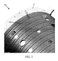
- Fig. 2 shows a combustion liner 100 as is described above. Similar to the liner 10 described above, the combustion liner 100 includes the forward end 12 and the aft end 14. Likewise, the combustion liner 100 includes a number of air mixing holes 110 arranged circumferentially around the combustion liner 100. The combustion liner 100 also includes a number of slots 120 with a number of cooling holes 130 extending therethrough. Other types of apertures, such as spark plug holes, flame detection holes, and the like may be used.
- the combustion liner 100 may include a number of angled slots or thimble fans 140. As is shown in Figs. 3 and 4 , each thimble fan 140 may include a substantially flat outer lip 150 surrounding a downwardly inclining wall 160. The outer lip 150 may extend around the inclining wall 160 in whole or in part. The outer lip 150 of the thimble fans 140 may be attached to the combustion liner 100 via welding or other types of conventional techniques.
- the inclining wall 160 may have any desired angle of incline.
- the inclining wall 160 maybe substantially flat as is shown or may have any desired contour and/or shape.
- the thimble fans 140 may have any desired size.
- the thimble fans 140 may have any shape that directs a flow of air at an angle into the combustion liner 100. Any number of thimble fans 140 may be used. The thimble fans 140 may be positioned anywhere and at any angle to the air mixing holes 110 along the combustion liner 100.
- the thimble fans 140 may be positioned upstream of the first row 26 of the airflow mixing holes 110. As described above, the air mixing holes 110 may interrupt the cooling airflow from the cooling holes 130. By positioning the thimble fans 140 upstream of the first row 26 of the mixing holes 110, the thimble fans 140 direct the airflow at the intersection of the fuel jet and the first row 26. Specifically, the airflow directed by the thimble fans 140 may prevent fuel and therefore flame from reaching the surface of the liner 100 so as to avoid localized overheating. Such a reduction should improve durability with respect to cracking, oxidation (specifically louver oxidation), creep deformation, thermal barrier coating spallation, etc. Durability issues about the adjacent cooling holes 130 also may be reduced. The thimble fans 140 thus should prevent overheating about the first row 26 of the air mixing holes 110 and both downstream and upstream thereof. The thimble fans 140 thus should increase the lifetime of the combustion liner 100.
- thimble fans 140 may take any desired size or shape.
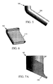
- Fig. 5 shows a thimble fan 140 in the form of an extended tube 200.
- Fig. 6 shows the thimble fan as an extended flattened tube 210.
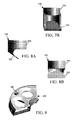
- Fig. 7A and 7B show a thimble fan 140 with a tube 220 leading to an angled flat surface 230.
- Figs. 8A and 8B show a thimble fan 140 with a tube 240 extending to a partially extended angled flat surface 250.
- Many other designs may be used herein.
- the thimble fans 140 also may be positioned on a combustor cap 260. As is shown in Fig. 9 , the combustor cap 260 may be positioned adjacent to the combustion liner 100. A number of thimble fans 140 may be positioned thereon. The thimble fans 140 may be positioned elsewhere.
Landscapes
- Engineering & Computer Science (AREA)
- Chemical & Material Sciences (AREA)
- Combustion & Propulsion (AREA)
- Mechanical Engineering (AREA)
- General Engineering & Computer Science (AREA)
- Gas Burners (AREA)
- Spray-Type Burners (AREA)
- Air Supply (AREA)
Applications Claiming Priority (1)
| Application Number | Priority Date | Filing Date | Title |
|---|---|---|---|
| US12/428,546 US20100269513A1 (en) | 2009-04-23 | 2009-04-23 | Thimble Fan for a Combustion System |
Publications (2)
| Publication Number | Publication Date |
|---|---|
| EP2246627A2 true EP2246627A2 (de) | 2010-11-03 |
| EP2246627A3 EP2246627A3 (de) | 2014-07-30 |
Family
ID=42291295
Family Applications (1)
| Application Number | Title | Priority Date | Filing Date |
|---|---|---|---|
| EP10160584.8A Withdrawn EP2246627A3 (de) | 2009-04-23 | 2010-04-21 | Lufteinlass mit Umlenkelement für ein Verbrennungssystem |
Country Status (4)
| Country | Link |
|---|---|
| US (1) | US20100269513A1 (de) |
| EP (1) | EP2246627A3 (de) |
| JP (1) | JP2010256005A (de) |
| CN (1) | CN101922734A (de) |
Cited By (2)
| Publication number | Priority date | Publication date | Assignee | Title |
|---|---|---|---|---|
| WO2012134698A1 (en) * | 2011-03-29 | 2012-10-04 | Siemens Energy, Inc. | Turbine combustion system cooling scoop |
| EP3263840A1 (de) * | 2016-06-28 | 2018-01-03 | Doosan Heavy Industries & Construction Co., Ltd. | Übergangsteilanordnung und brennkammer damit |
Families Citing this family (5)
| Publication number | Priority date | Publication date | Assignee | Title |
|---|---|---|---|---|
| US20130276450A1 (en) * | 2012-04-24 | 2013-10-24 | General Electric Company | Combustor apparatus for stoichiometric combustion |
| US20140216044A1 (en) * | 2012-12-17 | 2014-08-07 | United Technologoes Corporation | Gas turbine engine combustor heat shield with increased film cooling effectiveness |
| KR101766449B1 (ko) * | 2016-06-16 | 2017-08-08 | 두산중공업 주식회사 | 공기유도 캡 및 이를 구비하는 연소 덕트 |
| KR101986729B1 (ko) * | 2017-08-22 | 2019-06-07 | 두산중공업 주식회사 | 실 영역 집중냉각을 위한 냉각유로 구조 및 이를 포함하는 가스 터빈용 연소기 |
| EP4202301B1 (de) * | 2021-12-21 | 2026-03-11 | General Electric Company | Brennkammer mit verdünnungsöffnungen |
Family Cites Families (32)
| Publication number | Priority date | Publication date | Assignee | Title |
|---|---|---|---|---|
| US2638745A (en) * | 1943-04-01 | 1953-05-19 | Power Jets Res & Dev Ltd | Gas turbine combustor having tangential air inlets for primary and secondary air |
| GB594285A (en) * | 1944-03-16 | 1947-11-07 | Power Jets Ltd | Improvements relating to combustion apparatus |
| US2458497A (en) * | 1945-05-05 | 1949-01-11 | Babcock & Wilcox Co | Combustion chamber |
| US2601390A (en) * | 1946-11-07 | 1952-06-24 | Westinghouse Electric Corp | Combustion chamber for gas turbines with circumferentially arranged pulverized solidfuel and air nozzles |
| US2541171A (en) * | 1947-01-25 | 1951-02-13 | Kellogg M W Co | Air inlet structure for combustion chambers |
| US3581492A (en) * | 1969-07-08 | 1971-06-01 | Nasa | Gas turbine combustor |
| US3899882A (en) * | 1974-03-27 | 1975-08-19 | Westinghouse Electric Corp | Gas turbine combustor basket cooling |
| GB1537109A (en) * | 1975-10-23 | 1978-12-29 | Gen Electric | Gas turbine combustion system |
| US4199936A (en) * | 1975-12-24 | 1980-04-29 | The Boeing Company | Gas turbine engine combustion noise suppressor |
| US4688310A (en) * | 1983-12-19 | 1987-08-25 | General Electric Company | Fabricated liner article and method |
| US4622821A (en) * | 1985-01-07 | 1986-11-18 | United Technologies Corporation | Combustion liner for a gas turbine engine |
| US4700544A (en) * | 1985-01-07 | 1987-10-20 | United Technologies Corporation | Combustors |
| US4653279A (en) * | 1985-01-07 | 1987-03-31 | United Technologies Corporation | Integral refilmer lip for floatwall panels |
| US4875339A (en) * | 1987-11-27 | 1989-10-24 | General Electric Company | Combustion chamber liner insert |
| US4887432A (en) * | 1988-10-07 | 1989-12-19 | Westinghouse Electric Corp. | Gas turbine combustion chamber with air scoops |
| US5077969A (en) * | 1990-04-06 | 1992-01-07 | United Technologies Corporation | Cooled liner for hot gas conduit |
| US6149774A (en) * | 1998-06-10 | 2000-11-21 | Delsys Pharmaceutical Corporation | AC waveforms biasing for bead manipulating chucks |
| US6468669B1 (en) * | 1999-05-03 | 2002-10-22 | General Electric Company | Article having turbulation and method of providing turbulation on an article |
| US6260359B1 (en) * | 1999-11-01 | 2001-07-17 | General Electric Company | Offset dilution combustor liner |
| US6494044B1 (en) * | 1999-11-19 | 2002-12-17 | General Electric Company | Aerodynamic devices for enhancing sidepanel cooling on an impingement cooled transition duct and related method |
| US6484505B1 (en) * | 2000-02-25 | 2002-11-26 | General Electric Company | Combustor liner cooling thimbles and related method |
| US6349899B1 (en) * | 2000-04-04 | 2002-02-26 | The Boeing Company | Aircraft auxiliary air intake with ram and flush opening door |
| US6543233B2 (en) * | 2001-02-09 | 2003-04-08 | General Electric Company | Slot cooled combustor liner |
| GB2379499B (en) * | 2001-09-11 | 2004-01-28 | Rolls Royce Plc | Gas turbine engine combustor |
| US6722134B2 (en) * | 2002-09-18 | 2004-04-20 | General Electric Company | Linear surface concavity enhancement |
| US7104067B2 (en) * | 2002-10-24 | 2006-09-12 | General Electric Company | Combustor liner with inverted turbulators |
| US6681578B1 (en) * | 2002-11-22 | 2004-01-27 | General Electric Company | Combustor liner with ring turbulators and related method |
| US7010921B2 (en) * | 2004-06-01 | 2006-03-14 | General Electric Company | Method and apparatus for cooling combustor liner and transition piece of a gas turbine |
| US7007477B2 (en) * | 2004-06-03 | 2006-03-07 | General Electric Company | Premixing burner with impingement cooled centerbody and method of cooling centerbody |
| US7373778B2 (en) * | 2004-08-26 | 2008-05-20 | General Electric Company | Combustor cooling with angled segmented surfaces |
| FR2899315B1 (fr) * | 2006-03-30 | 2012-09-28 | Snecma | Configuration d'ouvertures de dilution dans une paroi de chambre de combustion de turbomachine |
| US8387396B2 (en) * | 2007-01-09 | 2013-03-05 | General Electric Company | Airfoil, sleeve, and method for assembling a combustor assembly |
-
2009
- 2009-04-23 US US12/428,546 patent/US20100269513A1/en not_active Abandoned
-
2010
- 2010-04-21 JP JP2010097474A patent/JP2010256005A/ja not_active Withdrawn
- 2010-04-21 EP EP10160584.8A patent/EP2246627A3/de not_active Withdrawn
- 2010-04-23 CN CN201010171628XA patent/CN101922734A/zh active Pending
Non-Patent Citations (1)
| Title |
|---|
| None |
Cited By (5)
| Publication number | Priority date | Publication date | Assignee | Title |
|---|---|---|---|---|
| WO2012134698A1 (en) * | 2011-03-29 | 2012-10-04 | Siemens Energy, Inc. | Turbine combustion system cooling scoop |
| KR20130143656A (ko) * | 2011-03-29 | 2013-12-31 | 지멘스 에너지, 인코포레이티드 | 터빈 연소 시스템 냉각 스쿠프 |
| US9127551B2 (en) | 2011-03-29 | 2015-09-08 | Siemens Energy, Inc. | Turbine combustion system cooling scoop |
| EP3263840A1 (de) * | 2016-06-28 | 2018-01-03 | Doosan Heavy Industries & Construction Co., Ltd. | Übergangsteilanordnung und brennkammer damit |
| US10495311B2 (en) | 2016-06-28 | 2019-12-03 | DOOSAN Heavy Industries Construction Co., LTD | Transition part assembly and combustor including the same |
Also Published As
| Publication number | Publication date |
|---|---|
| US20100269513A1 (en) | 2010-10-28 |
| CN101922734A (zh) | 2010-12-22 |
| EP2246627A3 (de) | 2014-07-30 |
| JP2010256005A (ja) | 2010-11-11 |
Similar Documents
| Publication | Publication Date | Title |
|---|---|---|
| CN101457937B (zh) | 燃烧器衬里套管嵌入件和相关方法 | |
| US8726631B2 (en) | Dual walled combustors with impingement cooled igniters | |
| JP6506503B2 (ja) | 燃焼器に燃料を供給するためのシステム | |
| EP1253379B1 (de) | Verfahren und Vorrichtung zur Kühlung von Gasturbinenbrennkammern | |
| CN100529544C (zh) | 用于燃气轮机的燃烧器衬的多孔衬片 | |
| CN104061595B (zh) | 用于燃气涡轮机的燃烧器的连续燃烧衬套 | |
| EP4148326A1 (de) | Kreuzfeuerrohr für gasturbine mit axial beabstandeten spülluftlochpaaren | |
| EP1253380B1 (de) | Verfahren und Vorrichtung zur Kühlung von Gasturbinenbrennkammern | |
| CN100520185C (zh) | 具有自由浮动旋流器的燃气涡轮发动机的燃烧器拱顶组件 | |
| EP2527740B1 (de) | Brenner mit Quetscheinsätzen | |
| JP4156245B2 (ja) | スロット冷却式燃焼器ライナ | |
| US20100212324A1 (en) | Dual walled combustors with impingement cooled igniters | |
| JP6659344B2 (ja) | 燃焼器内で冷却空気を利用するシステム及び方法 | |
| EP2246627A2 (de) | Lufteinlass mit Umlenkelement für ein Verbrennungssystem | |
| JP4838888B2 (ja) | ガスタービン燃焼器 | |
| CN102563697B (zh) | 用于点燃燃烧器的装置和方法 | |
| JP5507139B2 (ja) | 燃料ノズル中心体及びそれを組立てる方法 | |
| CN103443421B (zh) | 燃烧器及具备该燃烧器的燃气涡轮 | |
| EP3220047B1 (de) | Gasturbinenstromhülsenhalterung | |
| US20100043448A1 (en) | Gas turbine engine combustor and method for delivering purge gas into a combustion chamber of the combustor | |
| EP1258681B1 (de) | Verfahren und Vorrichtung zur Kühlung einer Gasturbinenverbrennungskammer | |
| JP2009085222A (ja) | タービュレータ付き後端ライナアセンブリ及びその冷却方法 | |
| CN106796031A (zh) | 火炬式点火器 | |
| CN102052689A (zh) | 用于涡轮机喷射器的冲击插入件 | |
| JP2011179812A (ja) | 燃焼器空気流スリーブ内の角度付き静翼 |
Legal Events
| Date | Code | Title | Description |
|---|---|---|---|
| PUAI | Public reference made under article 153(3) epc to a published international application that has entered the european phase |
Free format text: ORIGINAL CODE: 0009012 |
|
| AK | Designated contracting states |
Kind code of ref document: A2 Designated state(s): AT BE BG CH CY CZ DE DK EE ES FI FR GB GR HR HU IE IS IT LI LT LU LV MC MK MT NL NO PL PT RO SE SI SK SM TR |
|
| AX | Request for extension of the european patent |
Extension state: AL BA ME RS |
|
| PUAL | Search report despatched |
Free format text: ORIGINAL CODE: 0009013 |
|
| AK | Designated contracting states |
Kind code of ref document: A3 Designated state(s): AT BE BG CH CY CZ DE DK EE ES FI FR GB GR HR HU IE IS IT LI LT LU LV MC MK MT NL NO PL PT RO SE SI SK SM TR |
|
| AX | Request for extension of the european patent |
Extension state: AL BA ME RS |
|
| RIC1 | Information provided on ipc code assigned before grant |
Ipc: F23R 3/06 20060101AFI20140620BHEP |
|
| STAA | Information on the status of an ep patent application or granted ep patent |
Free format text: STATUS: THE APPLICATION IS DEEMED TO BE WITHDRAWN |
|
| 18D | Application deemed to be withdrawn |
Effective date: 20150131 |