EP2246652A2 - Heiz-/Kühlsystem für medizinischen Wärmetauscherdauerkatheter - Google Patents
Heiz-/Kühlsystem für medizinischen Wärmetauscherdauerkatheter Download PDFInfo
- Publication number
- EP2246652A2 EP2246652A2 EP10171931A EP10171931A EP2246652A2 EP 2246652 A2 EP2246652 A2 EP 2246652A2 EP 10171931 A EP10171931 A EP 10171931A EP 10171931 A EP10171931 A EP 10171931A EP 2246652 A2 EP2246652 A2 EP 2246652A2
- Authority
- EP
- European Patent Office
- Prior art keywords
- fluid
- heating
- bath
- light
- temperature
- Prior art date
- Legal status (The legal status is an assumption and is not a legal conclusion. Google has not performed a legal analysis and makes no representation as to the accuracy of the status listed.)
- Ceased
Links
- 238000001816 cooling Methods 0.000 title claims abstract description 40
- 238000010438 heat treatment Methods 0.000 claims abstract description 59
- 239000012809 cooling fluid Substances 0.000 claims abstract description 17
- 239000003507 refrigerant Substances 0.000 claims abstract description 16
- 239000012530 fluid Substances 0.000 claims description 76
- 238000001514 detection method Methods 0.000 claims description 6
- FAPWRFPIFSIZLT-UHFFFAOYSA-M Sodium chloride Chemical compound [Na+].[Cl-] FAPWRFPIFSIZLT-UHFFFAOYSA-M 0.000 abstract description 74
- 239000011780 sodium chloride Substances 0.000 abstract description 74
- 239000002826 coolant Substances 0.000 abstract description 19
- LYCAIKOWRPUZTN-UHFFFAOYSA-N Ethylene glycol Chemical compound OCCO LYCAIKOWRPUZTN-UHFFFAOYSA-N 0.000 description 120
- WGCNASOHLSPBMP-UHFFFAOYSA-N hydroxyacetaldehyde Natural products OCC=O WGCNASOHLSPBMP-UHFFFAOYSA-N 0.000 description 60
- XLYOFNOQVPJJNP-UHFFFAOYSA-N water Substances O XLYOFNOQVPJJNP-UHFFFAOYSA-N 0.000 description 60
- 229910003460 diamond Inorganic materials 0.000 description 27
- 239000010432 diamond Substances 0.000 description 27
- 230000001276 controlling effect Effects 0.000 description 7
- 238000000034 method Methods 0.000 description 7
- 230000008859 change Effects 0.000 description 5
- 239000000523 sample Substances 0.000 description 4
- 238000001990 intravenous administration Methods 0.000 description 3
- 230000000750 progressive effect Effects 0.000 description 3
- 230000009467 reduction Effects 0.000 description 3
- 238000010792 warming Methods 0.000 description 3
- 206010037660 Pyrexia Diseases 0.000 description 2
- 239000003570 air Substances 0.000 description 2
- 239000008280 blood Substances 0.000 description 2
- 210000004369 blood Anatomy 0.000 description 2
- 238000004891 communication Methods 0.000 description 2
- 230000002631 hypothermal effect Effects 0.000 description 2
- 238000012544 monitoring process Methods 0.000 description 2
- 230000004044 response Effects 0.000 description 2
- 238000001356 surgical procedure Methods 0.000 description 2
- 229920004943 Delrin® Polymers 0.000 description 1
- 206010020843 Hyperthermia Diseases 0.000 description 1
- 208000030886 Traumatic Brain injury Diseases 0.000 description 1
- DHKHKXVYLBGOIT-UHFFFAOYSA-N acetaldehyde Diethyl Acetal Natural products CCOC(C)OCC DHKHKXVYLBGOIT-UHFFFAOYSA-N 0.000 description 1
- 125000002777 acetyl group Chemical class [H]C([H])([H])C(*)=O 0.000 description 1
- 239000012080 ambient air Substances 0.000 description 1
- 230000036760 body temperature Effects 0.000 description 1
- 238000009833 condensation Methods 0.000 description 1
- 230000005494 condensation Effects 0.000 description 1
- 238000010276 construction Methods 0.000 description 1
- 238000010168 coupling process Methods 0.000 description 1
- 238000005859 coupling reaction Methods 0.000 description 1
- 230000003247 decreasing effect Effects 0.000 description 1
- 238000010586 diagram Methods 0.000 description 1
- 238000012377 drug delivery Methods 0.000 description 1
- 238000001704 evaporation Methods 0.000 description 1
- 230000008020 evaporation Effects 0.000 description 1
- 230000036541 health Effects 0.000 description 1
- 230000036031 hyperthermia Effects 0.000 description 1
- 230000002977 hyperthermial effect Effects 0.000 description 1
- 239000012212 insulator Substances 0.000 description 1
- 208000028867 ischemia Diseases 0.000 description 1
- 238000002955 isolation Methods 0.000 description 1
- 208000010125 myocardial infarction Diseases 0.000 description 1
- 230000003071 parasitic effect Effects 0.000 description 1
- 230000002572 peristaltic effect Effects 0.000 description 1
- 229920001296 polysiloxane Polymers 0.000 description 1
- 230000001105 regulatory effect Effects 0.000 description 1
- 238000002560 therapeutic procedure Methods 0.000 description 1
- 230000000007 visual effect Effects 0.000 description 1
Images



Classifications
-
- A—HUMAN NECESSITIES
- A61—MEDICAL OR VETERINARY SCIENCE; HYGIENE
- A61F—FILTERS IMPLANTABLE INTO BLOOD VESSELS; PROSTHESES; DEVICES PROVIDING PATENCY TO, OR PREVENTING COLLAPSING OF, TUBULAR STRUCTURES OF THE BODY, e.g. STENTS; ORTHOPAEDIC, NURSING OR CONTRACEPTIVE DEVICES; FOMENTATION; TREATMENT OR PROTECTION OF EYES OR EARS; BANDAGES, DRESSINGS OR ABSORBENT PADS; FIRST-AID KITS
- A61F7/00—Heating or cooling appliances for medical or therapeutic treatment of the human body
- A61F7/0085—Devices for generating hot or cold treatment fluids
-
- A—HUMAN NECESSITIES
- A61—MEDICAL OR VETERINARY SCIENCE; HYGIENE
- A61M—DEVICES FOR INTRODUCING MEDIA INTO, OR ONTO, THE BODY; DEVICES FOR TRANSDUCING BODY MEDIA OR FOR TAKING MEDIA FROM THE BODY; DEVICES FOR PRODUCING OR ENDING SLEEP OR STUPOR
- A61M1/00—Suction or pumping devices for medical purposes; Devices for carrying-off, for treatment of, or for carrying-over, body-liquids; Drainage systems
- A61M1/36—Other treatment of blood in a by-pass of the natural circulatory system, e.g. temperature adaptation, irradiation ; Extra-corporeal blood circuits
- A61M1/369—Temperature treatment
-
- A—HUMAN NECESSITIES
- A61—MEDICAL OR VETERINARY SCIENCE; HYGIENE
- A61F—FILTERS IMPLANTABLE INTO BLOOD VESSELS; PROSTHESES; DEVICES PROVIDING PATENCY TO, OR PREVENTING COLLAPSING OF, TUBULAR STRUCTURES OF THE BODY, e.g. STENTS; ORTHOPAEDIC, NURSING OR CONTRACEPTIVE DEVICES; FOMENTATION; TREATMENT OR PROTECTION OF EYES OR EARS; BANDAGES, DRESSINGS OR ABSORBENT PADS; FIRST-AID KITS
- A61F7/00—Heating or cooling appliances for medical or therapeutic treatment of the human body
- A61F2007/0054—Heating or cooling appliances for medical or therapeutic treatment of the human body with a closed fluid circuit, e.g. hot water
-
- A—HUMAN NECESSITIES
- A61—MEDICAL OR VETERINARY SCIENCE; HYGIENE
- A61F—FILTERS IMPLANTABLE INTO BLOOD VESSELS; PROSTHESES; DEVICES PROVIDING PATENCY TO, OR PREVENTING COLLAPSING OF, TUBULAR STRUCTURES OF THE BODY, e.g. STENTS; ORTHOPAEDIC, NURSING OR CONTRACEPTIVE DEVICES; FOMENTATION; TREATMENT OR PROTECTION OF EYES OR EARS; BANDAGES, DRESSINGS OR ABSORBENT PADS; FIRST-AID KITS
- A61F7/00—Heating or cooling appliances for medical or therapeutic treatment of the human body
- A61F2007/0095—Heating or cooling appliances for medical or therapeutic treatment of the human body with a temperature indicator
- A61F2007/0096—Heating or cooling appliances for medical or therapeutic treatment of the human body with a temperature indicator with a thermometer
-
- A—HUMAN NECESSITIES
- A61—MEDICAL OR VETERINARY SCIENCE; HYGIENE
- A61F—FILTERS IMPLANTABLE INTO BLOOD VESSELS; PROSTHESES; DEVICES PROVIDING PATENCY TO, OR PREVENTING COLLAPSING OF, TUBULAR STRUCTURES OF THE BODY, e.g. STENTS; ORTHOPAEDIC, NURSING OR CONTRACEPTIVE DEVICES; FOMENTATION; TREATMENT OR PROTECTION OF EYES OR EARS; BANDAGES, DRESSINGS OR ABSORBENT PADS; FIRST-AID KITS
- A61F7/00—Heating or cooling appliances for medical or therapeutic treatment of the human body
- A61F7/12—Devices for heating or cooling internal body cavities
- A61F2007/126—Devices for heating or cooling internal body cavities for invasive application, e.g. for introducing into blood vessels
-
- A—HUMAN NECESSITIES
- A61—MEDICAL OR VETERINARY SCIENCE; HYGIENE
- A61M—DEVICES FOR INTRODUCING MEDIA INTO, OR ONTO, THE BODY; DEVICES FOR TRANSDUCING BODY MEDIA OR FOR TAKING MEDIA FROM THE BODY; DEVICES FOR PRODUCING OR ENDING SLEEP OR STUPOR
- A61M2205/00—General characteristics of the apparatus
- A61M2205/36—General characteristics of the apparatus related to heating or cooling
-
- A—HUMAN NECESSITIES
- A61—MEDICAL OR VETERINARY SCIENCE; HYGIENE
- A61M—DEVICES FOR INTRODUCING MEDIA INTO, OR ONTO, THE BODY; DEVICES FOR TRANSDUCING BODY MEDIA OR FOR TAKING MEDIA FROM THE BODY; DEVICES FOR PRODUCING OR ENDING SLEEP OR STUPOR
- A61M2205/00—General characteristics of the apparatus
- A61M2205/36—General characteristics of the apparatus related to heating or cooling
- A61M2205/366—General characteristics of the apparatus related to heating or cooling by liquid heat exchangers
-
- A—HUMAN NECESSITIES
- A61—MEDICAL OR VETERINARY SCIENCE; HYGIENE
- A61M—DEVICES FOR INTRODUCING MEDIA INTO, OR ONTO, THE BODY; DEVICES FOR TRANSDUCING BODY MEDIA OR FOR TAKING MEDIA FROM THE BODY; DEVICES FOR PRODUCING OR ENDING SLEEP OR STUPOR
- A61M2230/00—Measuring parameters of the user
- A61M2230/50—Temperature
Definitions
- the present invention relates generally to methods and apparatus for exchanging heat with the body of a patient.
- the above-mentioned advantages in regulating temperature can be realized by cooling or heating the patient's entire body.
- the present invention understands that since many patients already are intubated with central venous catheters for other clinically approved purposes anyway such as drug delivery and blood monitoring, providing a central venous catheter that can also cool or heat the blood requires no additional surgical procedures for those patients.
- single purpose heat exchange catheters such as are made by Innercool Therapies of San Diego, CA and Radiant Medical of Portola Valley, CA can also be less optimally used.
- a heat exchange system for an indwelling heat exchange catheter includes a heat exchange bath configured to receive a conduit that carries working fluid to and from the catheter.
- the bath is filled with a heating/coolant fluid that exchanges heat with the working fluid.
- the system further includes a heat exchanger through which the heating/coolant fluid flows.
- the heat exchanger includes a refrigerant and a variable speed DC compressor.
- a heating/coolant fluid pump circulates the heating/coolant fluid between the heat exchanger and the heat exchange bath.
- the system includes a heating/coolant fluid level detector that communicates with the heating/coolant fluid.
- the system also includes a working fluid level detector that communicates with the working fluid.
- the system includes a controller that receives patient temperature input and target temperature input. The controller controls the temperature of the heating/coolant fluid in response to the patient temperature input and the target temperature input.
- the controller selectively energizes the working fluid pump.
- the system includes a lid on the bath. The lid is spaced above the top of the heating/cooling fluid.
- the system includes a display that shows a graph of temperature, e.g., patient temperature as a function of time. The display also presents qualitative comments on cooling and/or heating.
- a heat exchange system for an indwelling heat exchange catheter includes a working fluid circuit that is connected to the catheter to carry a working fluid to and from the catheter.
- a heating/cooling circuit is thermally coupled to the working fluid circuit and includes a heating/cooling fluid that exchanges heat with the working fluid.
- a refrigerating circuit is thermally coupled to the heating/cooling circuit.
- the refrigerating circuit includes a refrigerant that exchanges heat with the heating/cooling fluid.
- a display is connected to a controller for displaying temperature related to a patient having a cooling catheter intubated therein.
- the display includes means for providing a continuous graph of patient temperature as a function of time as the patient is heated or cooled via the cooling catheter.
- a fluid level detector in still another aspect of the present invention, includes a hollow container that defines a longitudinal axis and a radial axis.
- the fluid level detector also includes a light emitter that emits a light beam along a first light axis angled from the axes of the container.
- the direction of the light beam through the container is altered when the light beam is refracted by the fluid in the container.
- a light detector unit is distanced from the first light axis for receiving the light beam only when the light beam passes through fluid in the container and otherwise not receiving the light beam.
- the light detector unit outputs a detection signal when the light beam is detected.
- the detection signal is representative of fluid level in the container.
- a method for controlling a heat exchange apparatus that is connectable to an indwelling catheter for circulating saline thereto.
- the method includes determining a difference between a patient temperature and a target temperature. Based on the difference, one of two control modes are entered.
- a heat exchange system for an indwelling heat exchange catheter includes a working fluid circuit that is connected to the catheter to carry a working fluid to and from the catheter. Moreover, a heating/cooling circuit is thermally coupled to the working fluid circuit. The heating/cooling circuit includes a heating/cooling fluid that exchanges heat with the working fluid. A refrigerating circuit is thermally coupled to the heating/cooling circuit. The refrigerating circuit includes a refrigerant that exchanges heat with the heating/cooling fluid.
- the system also includes a controller for controlling the circulation of the working fluid, heating/cooling fluid and the refrigerant. The controller includes a program for determining the power required to heat or cool a patient in which the catheter is disposed.
- a patient heating/cooling system is shown and generally designated 10.
- the system 10 includes three separate fluid circuits: a saline circuit (also referred to as the working fluid circuit), a water glycol circuit (also referred to as the heating/cooling fluid circuit), and a refrigerant circuit (also referred to as the refrigerating fluid circuit.)
- a saline circuit also referred to as the working fluid circuit
- a water glycol circuit also referred to as the heating/cooling fluid circuit
- refrigerant circuit also referred to as the refrigerating fluid circuit.
- an indwelling heat exchange catheter 12 that can be inserted into a patient 13 during an operation is connected to a heat exchange bath 14 by a saline supply line 16.
- the supply line 16 is connected to a coiled or helical heat exchange tube 17 that is immersed in the bath 14 fluid to exchange heat therewith.
- the heat exchange tube 17 is connected a peristaltic tubing saline pump 18 by fluid line 20.
- the saline pump 18 draws saline from a saline reservoir 22 via fluid line 24.
- the saline reservoir 22 is disposed within a saline level detector 25 that, as described in detail below, helps control the saline pump 18 based on the level of saline in the level reservoir 22.
- the saline pump 18 has four modes: a standby or off mode, two treatment modes (i.e., two treatment speeds), and an idle mode wherein the saline pump 18 operates very slowly, but does not stop. In the idle mode, the patient 13 is effectively thermally decoupled from the heating/cooling system 10.
- a saline source 26 provides saline to the saline reservoir 22 via fluid line 28.
- the saline source 26 is an intravenous (IV) bag and a line clamp 27 is installed on fluid line 28 between the saline source 26 and the saline reservoir 22. It is to be understood that after the saline reservoir 22 is filled the line clamp 27 is clamped on fluid line 28 to isolate the saline source 26 from the saline reservoir 22.
- Figure 1 shows a saline return line 29 communicates saline from the catheter 12 to the saline reservoir 22 to complete the saline circuit. It is to be appreciated that the tubes 16, 17, 20, 24, and 29 can be provided as a disposable IV tubing set.
- Figure 1 also shows a system controller 30 that is connected to the saline level detector 25 via electrical line 32 and electrical line 34, i.e., one for each infrared detector that is associated with the saline level detector 25 as described below.
- the system controller 30 is also connected to a safety switch 36 of the saline pump 18 via electrical line 38.
- the system controller 30 receives signals from the saline level detector 25 regarding the level of saline therein and uses this information to control the saline pump 18, including opening the safety switch 36 to de-energize the saline pump 18 under certain low saline level conditions.
- saline is circulated to and from the catheter 12 through the helical heat exchange tube 17 in the heat exchange bath 14.
- the heat exchange bath 14 is filled with heating/cooling fluid, preferably water glycol.
- the water glycol can be heated or cooled in order to heat or cool the saline and thus, increase or decrease the temperature of the patient 13 into which the catheter 12 is inserted.
- the preferred working fluid is saline, but any similar fluid well known in the art can be used.
- the water glycol circuit communicates with a chiller/heater 40 via a water glycol supply line 42 and a water glycol return line 44.
- a water glycol pump 46 is installed in the water glycol return line 44 to circulate water glycol through the water glycol circuit.
- Figure 1 shows that the heat exchange bath 14 is also in fluid communication with a water glycol reservoir 47 installed within a water glycol level detector 48 via fluid line 50.
- the water glycol level detector 48 is used to determine the level of water glycol within the heat exchange bath 14.
- system controller 30 is connected to the chiller/heater 40 via electrical lines 52 and 54. Moreover, the system controller 30 is connected to a safety switch 55 at the water glycol pump 46 via electrical line 56 and to the coolant level detector 48 via electrical line 58 and electrical line 60. Thus, the system controller 30 can control the operation of the chiller/heater 40 based on signals from a temperature monitor, described below, and control the operation of the water glycol pump 46 based on level signals from infrared detectors, also described below, that are disposed within the water glycol level detector 48. As shown, the system controller 300 is also connected to a temperature sensor 57 placed at the outlet of the chiller/heater via electrical line 59. The controller 30 uses input from the temperature sensor 57 to control the chiller/heater 40 and other system 10 components.
- the chiller/heater 40 can heat or cool the water glycol.
- the water glycol exchanges heat with the saline.
- the water glycol can be used to heat or cool saline and in turn, heat or cool the patient in which the catheter 12 is intubated.
- water glycol is the preferred heating/cooling fluid. However, any other fluid with similar properties can be used.
- a variable speed direct current (DC) compressor 62 is in fluid communication with the chiller/heater 40 via a refrigerant supply line 64 and a refrigerant return line 66. It is to be understood that the compressor 62 is filled with refrigerant, e.g., R134a.
- a compressor controller 68 is connected to the compressor 62 via an electrical line 70.
- the system controller 30 is connected to the compressor controller 68 via electrical line 72.
- the compressor controller 68 is also connected to a heater, described below, within the chiller/heater 40 via electrical line 73.
- the system controller 30 receives temperature signals from the temperature monitor, described below, and uses these signals to control the operation of the compressor 62 and the heater.
- the compressor 62 is used to cool the water glycol that is pumped through the chiller/heater 40 by the water glycol pump 46.
- a DC power supply 74 is connected to the system controller 30 by an electrical line 76.
- the DC power supply 74 preferably is connected to an isolation transformer (XFMR) 78 by electrical line 80.
- the XFMR 78 can be connected to an alternating current (AC) input 82, e.g., a standard one hundred and twenty volt (120V) wall outlet, via a power cord 84.
- AC alternating current
- a temperature monitor 86 is connected to the system controller 30 via an electrical line 88.
- a first patient temperature probe 90 and a second patient temperature probe 92 preferably are connected to the temperature monitor 86 via electrical lines 94 and 96, respectively.
- the temperature monitor 86 uses the temperature probes 90, 92 to monitor the temperature of the patient 13.
- the temperature monitor 86 sends signals to the system controller 30 representing the temperature of the patient 13. These signals are used by the system controller 30 to control the operation of the chiller/heater 40, the saline pump 18, and the DC compressor 62.
- Figure 1 shows a display device 98 that is connected to the system controller 30 via electrical line 100 and electrical line 102.
- the display device 98 provides a visual indication of the patient's temperature and the bath temperature.
- the display device 98 can be used to output graphs of minute by minute patient temperature (for, e.g., twenty one days) and water glycol bath temperature.
- the display device 98 can also be used to provide information regarding the cooling power required by the patient, whether the system is heating or cooling the bath, and at which rate, e.g., low, medium, or maximum, the system is heating or cooling the bath.
- the display device 98 can display the current patient temperature and the patient target temperature.
- the display device 98 also includes a control panel 104 to allow a user, i.e., a doctor or a nurse, to input data, such as a target patient temperature, to the system 10.
- the preferred heat exchange bath 14 includes a bottom 110 having a generally cylindrical continuous sidewall 112 extending therefrom. As shown, the bottom 110 of the bath 14 is formed with a hole 114 and the water glycol supply line 42 is connected thereto. A preferably vertical standpipe 116 extends from the end of the water glycol supply line 42 into the interior of the bath 14. In a preferred embodiment, the standpipe 116 is perforated along its length with a series of four hole rings 118 out of which water glycol flows into the bath 14. These four hole rings 118 ensure radial movement of the water glycol through the heat exchange tubing 17, i.e., between and across the turns of the coil. It can be appreciated that in lieu of the standpipe 116, a small impeller (not shown) can be mounted on the bottom 110 of the bath 14 to circulate the water glycol therein.
- a small impeller (not shown) can be mounted on the bottom 110 of the bath 14 to circulate the water glycol therein.
- the generally spiral-shaped heat exchange tubing 17 is disposed within the bath 14 such that when the bath 14 is filled with water glycol the heat exchange tubing 17 is fully immersed in the water glycol.
- Figure 2 shows that the saline supply line 16 is connected to one end of the heat exchange tubing 17.
- the fluid line 20 from the saline pump 18 is connected to the other end of the heat exchange tubing 17.
- four vertical stanchions 122 extend up from the bottom 110 of the bath 14 and touch the outer surface of the tubing set 120.
- the heat exchange tubing 17 can rest against the sidewall 112 of the bath 14.
- FIG. 2 further shows that the bath 14 is covered by a lid 124.
- the bottom of the lid 124 is spaced above the top of the water glycol within the bath 14 in order to establish a dead air space 126 between the lid 124 and the water glycol.
- This dead air space 126 acts as an insulator to minimize parasitic heat loads, control the evaporation of the water glycol, and prevent progressive overfilling of the bath 14 by condensation from the ambient air.
- the lid 124 can be sealed against the wall 112 by a resilient, preferably silicone, gasket 128.
- the saline level detector 25 includes a housing 130 that is preferably made from acetal, e.g., Delrin® manufactured by E.I. Dupont De Nemours & Co. of Delaware.
- the housing 130 is formed with a preferably "U" shaped central bore 132 in which the preferably clear saline reservoir 22 is disposed.
- Figure 3 shows that the housing is formed with a first transverse bore 134, a second transverse bore 136, and a third transverse bore 138 leading to the central bore 132.
- the saline level detector 25 includes a light emitter, e.g., an infrared light emitting diode (IR LED) 140, that is mounted in the first bore 134 on one side of the level detector 22.
- IR LED infrared light emitting diode
- two light detectors such as a first IR detector 142 and a second IR detector 144, are placed on the opposite side of the saline level detector 25 from the LED 140 within the second and third transverse bores 136, 138.
- the detectors 142, 144 are photodiodes or phototransistors.
- the IR light beam can be modulated, i.e. pulsed, e.g., at nine and a half kiloHertz (9.5 kHz), to avoid false detections caused, e.g., by other light sources placed in the same room as the level detector 25 and/or bubbles in the saline reservoir 22.
- the first IR detector 142 and second IR detector 144 can be connected to upper and lower tone detectors 150, 152, respectively, which output signals only when they receive an input of, e.g., 9.5 kHz. It can be appreciated that when the saline level within the level detector falls below a predetermined level, the controller 30 can activate an alarm at the display device 98.
- the alarm can include a visible alarm, e.g., a light, or an audible alarm, e.g., a buzzer.
- a visible alarm e.g., a light
- an audible alarm e.g., a buzzer.
- the controller 30 can de-energize the saline pump 18 by opening the safety switch 36.
- FIG. 4 shows the details regarding one preferred, non-limiting implementation of the chiller/heater 40.
- the chiller/heater 40 is a shell-and-tube heat exchanger having a lower chamber 160, an upper chamber 162, and plural tubes 164 communicating water glycol therebetween. It is to be understood that water glycol flows into the lower chamber 160, up the tubes 164, into to the upper chamber 162, and out of the upper chamber 162 to the heat exchange bath 14. Refrigerant, e.g., R134a, flows around the tubes 164 to cool the water glycol therein.
- a resistive heater element 166 is disposed in the lower chamber 160 and extends partially up an enlarged center tube 168 for heating the water glycol in the chiller/heater 60. It is to be appreciated that in a less preferred embodiment the chiller/heater 40 and the heat exchange bath 14 can be combined into a single unit.
- T pt the patient temperature
- T target the patient target temperature
- T bath the bath temperature
- T pt is received from the temperature monitor 86, specifically from the second temperature probe 92.
- ⁇ T a temperature differential
- decision diamond 204 it is determined whether the absolute value of ⁇ T is less than a predetermined amount, e.g., one tenth of a degree Celsius (0.1 °C).
- the logic moves to block 206 where the system 10 enters maximum cooling mode or maximum warming mode. It is to be understood that if ⁇ T is negative the saline pump 18 is brought to full speed, the compressor 62 is turned on at high speed, and the heater 166 is turned off to cool the patient. Conversely, if ⁇ T is positive, the saline pump 18 is brought to full speed, the compressor 62 is turned off, and the heater 166 is turned on to warm the patient.
- the logic moves to decision diamond 210 where it is determined whether the absolute value of dT pt /dt is greater than thirty six hundredths of a degree Celsius per hour (0.36 °C/hr). If not, the logic continues to block 212 and a new T bath is determined.
- the new T bath is determined based on the rate of change of patient temperature. A higher rate of change results in a new T bath that is further away from the current T bath and a lower rate of change results in a new T bath that is closer to the current T bath .
- dT pt /dt is indeed greater than 0.36 °C/hr and negative, meaning that the patient 13 is being rapidly cooled and does not require saline circulation through the catheter.
- the logic moves to block 214 where the saline pump 18 is idled. Thereafter, the logic moves to 212 and a new T bath is determined.
- the logic proceeds to block 216, wherein the compressor 62 and chiller/heater 40 are operated in accordance with the rules set forth below to achieve the new T bath .
- the saline pump 18 is selectively idled per the following rules:
- Figure 6 shows the linear mode operation logic of the present invention.
- a do loop is entered wherein while in the linear mode, the succeeding steps are performed.
- several "fail safe" tests are monitored for to revert to maximum cooling or heating in the event that a rapid patient temperature change occurs. For instance, at decision diamond 232, if it is determined that ⁇ T is greater than one half a degree Celsius (0.5 °C) and has a negative sign, the system exits linear mode and enters maximum cooling mode at block 234.
- ⁇ T is positive and greater than three tenths of a degree Celsius (0.3 °C)
- the logic moves to block 238 where the linear mode is exited and the maximum warming mode is entered.
- dT pt /dt is determined using the equation described above.
- dT pt /dt is greater than seven tenths of a degree Celsius per hour (0.7 °C/hr) for the last ten (10) minutes. If so, the logic moves to block 234 where the linear mode is exited and the maximum cooling mode is entered. If dT pt /dt is less than 0.7 °C/hr for the last 10 minutes, the logic returns to decision diamond 232 and continues as described above.
- the control logic of the compressor commences at block 250 with a do loop, wherein after a new T bath is determined, the following steps are performed.
- decision diamond 252 it is determined whether the new T bath is greater than the current T bath . If the new T bath is lower than the current T bath , the logic moves to block 254 and the heater 166 is deactivated while the compressor 62 is activated at maximum speed to cool the water glycol.
- decision diamond 256 it is determined whether the current bath temperature is within a predetermined range, e.g., two-tenths degrees Celsius (0.2 °C) of the new T bath . If not, the logic moves to block 258 where the cooling of the water glycol is continued. The logic then returns to decision diamond 256. If the current bath temperature is within the predetermined range of the new T bath , the logic moves to block 260 wherein the compressor speed is progressively reduced.
- a predetermined range e.g., two-tenths degrees Celsius (0.2 °C) of the new T bath .
- the logic moves to decision diamond 262 where it is determined whether the current temperature is stable at the new T bath . If so, the logic moves to block 264 and the compressor 62 is held at the current speed to maintain the temperature at the new T bath . If, at decision diamond 262, the temperature has not stabilized at the new T bath , the logic moves to decision diamond 266 where it is determined whether the minimum compressor speed has been reached. If the minimum compressor speed has not been reached, the logic returns to block 260 and continues as described above. Conversely, if the minimum compressor speed has been reached, the logic moves to block 268 where the heater power is progressively increased.
- the logic continues to decision diamond 270 where it is determined if the current temperature has stabilized at the new T bath . If not, the logic returns to block 268 where the heater power continues to be progressively increased. If, on the other hand, the current temperature has stabilized at T bath the logic moves to block 272 where the current power is maintained. Thereafter, the logic moves to block 264 where the compressor is idled at the current speed, in this case the lowest speed, in order to maintain the temperature at T bath . In a preferred, non-limiting embodiment, the lowest temperature to which the bath can be commanded is one-half degree Celsius (0.5 °C).
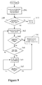
- the logic proceeds to decision diamond 274 where it is determined whether the new T bath is less than or equal to a predetermined upper bath limit, e.g., forty two degrees Celsius (42 °C). If the new T bath is less than the upper bath limit, the logic moves to Figure 8 . However, if the new T bath is equal to the upper bath limit, the logic moves to Figure 9 .
- a predetermined upper bath limit e.g., forty two degrees Celsius (42 °C).
- the logic proceeds to block 276 where the compressor 62 is activated at minimum speed and the heater 166 is activated at maximum power. From block 276, the logic moves to decision diamond 278 where it is determined if the current temperature is within a predetermined range, e.g., two-tenths degrees Celsius (0.2 °C) of the new T bath . If not, the logic proceeds to block 280 and the heating of the water glycol is continued. If the temperature is within the predetermined range, the logic continues to block 282 where the heater power is progressively reduced.
- a predetermined range e.g., two-tenths degrees Celsius (0.2 °C)
- decision diamond 284 it is determined whether the current temperature has stabilized at the new T bath . If the current temperature has stabilized at the new T bath , the current heater power is maintained to maintain the temperature at the new T bath . On the other hand, if the current temperature has not stabilized, the logic proceeds to decision diamond 288 where it is determined if the heater duty cycle is equal to zero (0). If not, the logic returns to block 282 where the progressive reduction of the heater power is continued.
- the logic moves to Figure 9 .
- the compressor is deactivated and the heater is activated at maximum power.
- the logic moves to decision diamond 298 where it is determined whether the temperature is within a predetermined range, e.g., two-tenths degrees Celsius (0.2 °C), of the new T bath . If not, the heating of the water glycol is continued at block 300. If the current temperature is within 3 °C of the new T bath , the logic proceeds to block 302 where the power of the heater 166 is progressively reduced. Then, at decision diamond 304, it is determined whether the temperature has stabilized at the new T bath .
- a predetermined range e.g., two-tenths degrees Celsius (0.2 °C)
- the system described above has two nested closed-loop controllers: an outer loop and an inner loop.
- the outer loop is directly responsible for controlling the patient temperature and is driven by the temperature difference between T target and T pt .
- the inner loop is directly responsible for the coolant temperature, i.e., T bath , that is established by the system controller 30.
- the outer loop logic i.e., the overall operation logic and linear mode operation logic describe above, resides in the system controller 30.
- the inner loop control logic i.e., the compressor control logic described above, resides in the compressor controller 68.
- the compressor controller 68 controls the compressor 62 and the heater 166, as described above, in order to achieve the new T bath .
- the compressor controller 68 has two means of control over the compressor 62. First, it can turn the power to compressor 62 on and off via a solid-state DC relay. Second, it can modulate the compressor speed between a maximum value, e.g., thirty five hundred revolutions per minute (3,500 RPM), and a minimum value, e.g., two thousand revolutions per minute (2,000 RPM).
- a maximum value e.g., thirty five hundred revolutions per minute (3,500 RPM)
- a minimum value e.g., two thousand revolutions per minute (2,000 RPM).
- the compressor controller 68 has only duty-cycle control over the heater 166.
- the compressor controller 68 can modulate the heater power anywhere between zero percent (0 %), i.e., off, and one hundred percent (100 %), i.e., on.
- the heater 166 has a fixed one second (1 s) pulse period.
- the heater 166 has a maximum power of two hundred and forty watts (240 w).
- a fifty percent (50 %) duty cycle corresponds to one hundred and twenty watts (120 w) of time-averaged input power to the water glycol and a twenty five percent (25 %) duty cycle would correspond to sixty watts (60 w) of time-averaged input power.
- the saline pump 18 preferably is idled to thermally de-couple the patient 13 from the cooling system 10 and the T bath is increased, e.g., by energizing the heater 166, to approximately twenty-five degrees Celsius (25 °C).
- T pt will discontinue the rapid decrease described above while T bath is increased.
- the power required to cool the patient can be viewed at the display device 98. It is to be understood that the power equation described below is most accurate for a patient having a weight of approximately seventy-five kilograms (75 kg). Accordingly, the power used to cool a patient can be determined using the following equation: dT pt / dt °C / min x 60 min / hr 1.4 °C / hr x 100 ⁇ w x - 1 where:
- a heat exchange system for an indwelling heat exchange catheter comprising: a heat exchange bath configured to receive a conduit carrying working fluid to and from the catheter; a heating/coolant fluid in the bath to exchange heat with the working fluid; a heat exchanger through which the heating/coolant fluid flows, the heat exchanger including a refrigerant and a variable speed DC compressor; and a heating/coolant fluid pump circulating the heating/coolant fluid between the heat exchanger and the heat exchange bath.
- the system may further comprise a heating/coolant fluid level detector communicating with the heating/coolant fluid.
- the system may further comprise a working fluid level detector communicating with the working fluid.
- the system may further comprise at least one controller receiving patient temperature input and target temperature input, the controller controlling a heating/coolant fluid temperature in response thereto.
- the system may further comprise a working fluid pump to circulate the working fluid through the catheter, the working fluid pump being selectively energized by the controller.
- the system may further comprise a lid on the bath spaced above a top of the heating/coolant fluid.
- the system may further comprise a display showing at least one graph of temperature.
- the display may present qualitative comments on cooling.
- a display connected to a controller for displaying temperature related to a patient having a cooling catheter intubated therein, comprising: means for providing a continuous graph of patient temperature as the patient is heated or cooled via the cooling catheter.
- a method for controlling a heat exchange apparatus connectable to an indwelling catheter for circulating saline thereto comprising: determining a difference between an actual temperature and a target temperature; and based on the difference, entering one of at least two control modes.
Landscapes
- Health & Medical Sciences (AREA)
- Heart & Thoracic Surgery (AREA)
- Vascular Medicine (AREA)
- Public Health (AREA)
- Biomedical Technology (AREA)
- Life Sciences & Earth Sciences (AREA)
- Animal Behavior & Ethology (AREA)
- General Health & Medical Sciences (AREA)
- Engineering & Computer Science (AREA)
- Veterinary Medicine (AREA)
- Cardiology (AREA)
- Anesthesiology (AREA)
- Hematology (AREA)
- Thermotherapy And Cooling Therapy Devices (AREA)
- External Artificial Organs (AREA)
- Media Introduction/Drainage Providing Device (AREA)
Applications Claiming Priority (3)
| Application Number | Priority Date | Filing Date | Title |
|---|---|---|---|
| US09/965,560 US6581403B2 (en) | 2001-09-25 | 2001-09-25 | Heating/cooling system for indwelling heat exchange catheter |
| EP09166059A EP2119988A3 (de) | 2001-09-25 | 2002-09-23 | Heiz-/Kühlsystem für medizinischen Wärmetauscherdauerkatheter |
| EP02766336A EP1430258B1 (de) | 2001-09-25 | 2002-09-23 | Heiz-Kühlsystem für medizinische Wärmetauscher-Dauerkatheter |
Related Parent Applications (2)
| Application Number | Title | Priority Date | Filing Date |
|---|---|---|---|
| EP02766336.8 Division | 2002-09-23 | ||
| EP09166059.7 Division | 2009-07-21 |
Publications (2)
| Publication Number | Publication Date |
|---|---|
| EP2246652A2 true EP2246652A2 (de) | 2010-11-03 |
| EP2246652A3 EP2246652A3 (de) | 2012-03-14 |
Family
ID=25510146
Family Applications (3)
| Application Number | Title | Priority Date | Filing Date |
|---|---|---|---|
| EP09166059A Ceased EP2119988A3 (de) | 2001-09-25 | 2002-09-23 | Heiz-/Kühlsystem für medizinischen Wärmetauscherdauerkatheter |
| EP10171931A Ceased EP2246652A3 (de) | 2001-09-25 | 2002-09-23 | Heiz-/Kühlsystem für medizinischen Wärmetauscherdauerkatheter |
| EP02766336A Expired - Lifetime EP1430258B1 (de) | 2001-09-25 | 2002-09-23 | Heiz-Kühlsystem für medizinische Wärmetauscher-Dauerkatheter |
Family Applications Before (1)
| Application Number | Title | Priority Date | Filing Date |
|---|---|---|---|
| EP09166059A Ceased EP2119988A3 (de) | 2001-09-25 | 2002-09-23 | Heiz-/Kühlsystem für medizinischen Wärmetauscherdauerkatheter |
Family Applications After (1)
| Application Number | Title | Priority Date | Filing Date |
|---|---|---|---|
| EP02766336A Expired - Lifetime EP1430258B1 (de) | 2001-09-25 | 2002-09-23 | Heiz-Kühlsystem für medizinische Wärmetauscher-Dauerkatheter |
Country Status (5)
| Country | Link |
|---|---|
| US (1) | US6581403B2 (de) |
| EP (3) | EP2119988A3 (de) |
| AT (1) | ATE437346T1 (de) |
| DE (1) | DE60233059D1 (de) |
| WO (1) | WO2003027589A1 (de) |
Families Citing this family (58)
| Publication number | Priority date | Publication date | Assignee | Title |
|---|---|---|---|---|
| US6974463B2 (en) * | 1999-02-09 | 2005-12-13 | Innercool Therapies, Inc. | System and method for patient temperature control employing temperature projection algorithm |
| US7287398B2 (en) * | 2001-09-25 | 2007-10-30 | Alsius Corporation | Heating/cooling system for indwelling heat exchange catheter |
| US6338727B1 (en) | 1998-08-13 | 2002-01-15 | Alsius Corporation | Indwelling heat exchange catheter and method of using same |
| US8128595B2 (en) | 1998-04-21 | 2012-03-06 | Zoll Circulation, Inc. | Method for a central venous line catheter having a temperature control system |
| AU2003241673A1 (en) * | 2002-06-17 | 2003-12-31 | Atsuo Mori | Catheter for topical cooling and topical cooling device using the same |
| US7179279B2 (en) * | 2002-09-30 | 2007-02-20 | Medtronic Physio Control Corp. | Rapid induction of mild hypothermia |
| US7087075B2 (en) | 2002-09-30 | 2006-08-08 | Medtronic Emergency Response Systems, Inc. | Feedback system for rapid induction of mild hypothermia |
| CA2411569A1 (en) * | 2002-11-12 | 2004-05-12 | Ross E. Mantle | Medical device for the extravascular recirculation of fluid in body cavities at controlled temperature and pressure |
| US7056282B2 (en) | 2002-12-23 | 2006-06-06 | Medtronic Emergency Response Systems, Inc. | Coolant control for rapid induction of mild hypothermia |
| US7278984B2 (en) * | 2002-12-31 | 2007-10-09 | Alsius Corporation | System and method for controlling rate of heat exchange with patient |
| US7300453B2 (en) * | 2003-02-24 | 2007-11-27 | Innercool Therapies, Inc. | System and method for inducing hypothermia with control and determination of catheter pressure |
| US20040199114A1 (en) * | 2003-04-01 | 2004-10-07 | Alsius Corporation | Intravascular heat exchange catheter with tissue preservative |
| EP1779049B1 (de) * | 2003-08-06 | 2019-02-20 | Zoll Circulation, Inc. | Heiz/kühlsystem für wärmetausch-dauerkatheter |
| EP1520568B1 (de) * | 2003-10-03 | 2011-07-27 | Mario Zanotti | Wärmeaustauschvorrichtung, insbesondere zur Anwendung der Wärmebehandlung |
| US20060064146A1 (en) * | 2004-09-17 | 2006-03-23 | Collins Kenneth A | Heating/cooling system for indwelling heat exchange catheter |
| US8672988B2 (en) * | 2004-10-22 | 2014-03-18 | Medtronic Cryocath Lp | Method and device for local cooling within an organ using an intravascular device |
| US8491644B1 (en) * | 2005-02-22 | 2013-07-23 | Medivance Incorporated | Portable, refrigerant-based apparatus and method for rapid systemic patient cooling |
| US20060190062A1 (en) * | 2005-02-23 | 2006-08-24 | Worthen William J | System and method for reducing shivering when using external cooling pads |
| US7070612B1 (en) | 2005-02-23 | 2006-07-04 | Alsius Corporation | System and method for bringing hypothermia rapidly onboard |
| US20060190066A1 (en) * | 2005-02-23 | 2006-08-24 | Worthen William J | System and method for bringing hypothermia rapidly onboard |
| US7425216B2 (en) * | 2005-03-01 | 2008-09-16 | Alsius Corporation | System and method for treating cardiac arrest and myocardial infarction |
| US7892269B2 (en) * | 2005-04-18 | 2011-02-22 | Zoll Circulation, Inc. | External heat exchange pad for patient |
| EP2929862B1 (de) | 2005-04-27 | 2017-02-08 | Zoll Circulation, Inc. | System zur bereitstellung verbesserter wärmeübertragung aus einem körper |
| US20060276864A1 (en) * | 2005-06-03 | 2006-12-07 | Alsius Corporation | Systems and methods for sensing patient temperature in temperature management system |
| US20060293732A1 (en) * | 2005-06-27 | 2006-12-28 | Collins Kenneth A | Thermoelectric cooler (TEC) heat exchanger for intravascular heat exchange catheter |
| US7181927B2 (en) * | 2005-07-01 | 2007-02-27 | Alsius Corporation | Primary heat exchanger for patient temperature control |
| US7951182B2 (en) * | 2005-07-14 | 2011-05-31 | Zoll Circulation, Inc. | System and method for leak detection in external cooling pad |
| US20180311071A1 (en) | 2005-10-21 | 2018-11-01 | Daniel R. BURNETT | Method and apparatus for peritoneal oxygenation |
| US20070093697A1 (en) * | 2005-10-21 | 2007-04-26 | Theranova, Llc | Method and apparatus for detection of right to left shunting in the cardiopulmonary vasculature |
| US7822485B2 (en) | 2006-09-25 | 2010-10-26 | Zoll Circulation, Inc. | Method and apparatus for spinal cooling |
| US20080097562A1 (en) * | 2006-10-19 | 2008-04-24 | Dyamed Biotech Pte Ltd | System For Chemohyperthermia Treatment |
| US7867266B2 (en) | 2006-11-13 | 2011-01-11 | Zoll Circulation, Inc. | Temperature management system with assist mode for use with heart-lung machine |
| US7892270B2 (en) * | 2006-11-21 | 2011-02-22 | Zoll Circulation Inc. | Temperature management system and method for burn patients |
| US8353893B2 (en) | 2007-03-07 | 2013-01-15 | Zoll Circulation, Inc. | System and method for rapidly cooling cardiac arrest patient |
| AU2008237177A1 (en) | 2007-04-05 | 2008-10-16 | Velomedix, Inc | Automated therapy system and method |
| US20080249467A1 (en) * | 2007-04-05 | 2008-10-09 | Daniel Rogers Burnett | Device and Method for Safe Access to a Body Cavity |
| US9737692B2 (en) * | 2007-05-18 | 2017-08-22 | Zoll Circulation, Inc. | System and method for effecting non-standard fluid line connections |
| US8439960B2 (en) | 2007-07-09 | 2013-05-14 | Velomedix, Inc. | Hypothermia devices and methods |
| US7827005B2 (en) * | 2008-04-21 | 2010-11-02 | Zoll Circulation, Inc. | System and method for testing heat exchange system for heat exchange catheter |
| WO2010091364A1 (en) * | 2009-02-06 | 2010-08-12 | Velomedix, Inc. | Method and apparatus for inducing therapeutic hypothermia |
| US9301871B2 (en) | 2009-02-26 | 2016-04-05 | Advanced Cooling Therapy, Inc. | Devices and methods for controlling patient temperature |
| US8464171B2 (en) * | 2009-06-26 | 2013-06-11 | Eppendorf Ag | Device for displaying a function chart |
| WO2012006625A2 (en) | 2010-07-09 | 2012-01-12 | Velomedix, Inc. | Method and apparatus for pressure measurement |
| DE102011016508A1 (de) | 2011-04-08 | 2012-10-11 | Sorin Group Deutschland Gmbh | Temperiervorrichtung für den Einsatz in fluidbasierten Hyper-/Hypothermie-Systemen |
| US10045881B2 (en) | 2011-09-28 | 2018-08-14 | Zoll Circulation, Inc. | Patient temperature control catheter with helical heat exchange paths |
| US8888832B2 (en) | 2011-09-28 | 2014-11-18 | Zoll Circulation, Inc. | System and method for doubled use of patient temperature control catheter |
| JP6110386B2 (ja) | 2011-09-30 | 2017-04-05 | ゾール サーキュレイション インコーポレイテッドZOLL Circulation,Inc. | カテーテル装置およびカテーテル装置を含むシステム |
| EP2698176B1 (de) | 2012-08-13 | 2017-03-15 | Sorin Group Deutschland GmbH | Verfahren und Vorrichtung zur Desinfizierung einer Temperatursteuerungsvorrichtung für die menschliche Körpertemperatursteuerung während der extrakorporalen Zirkulation |
| EP2698177B1 (de) | 2012-08-13 | 2015-01-14 | Sorin Group Deutschland GmbH | Verfahren zur Regelung eines Desinfektionsstatus einer Temperaturregelvorrichtung und Temperaturregelvorrichtung zur Regelung der menschlichen Körpertemperatur während extrakorporaler Zirkulation |
| US9241827B2 (en) | 2012-09-28 | 2016-01-26 | Zoll Circulation, Inc. | Intravascular heat exchange catheter with multiple spaced apart discrete coolant loops |
| US9801756B2 (en) | 2012-09-28 | 2017-10-31 | Zoll Circulation, Inc. | Intravascular heat exchange catheter and system with RFID coupling |
| US9433528B2 (en) | 2012-09-28 | 2016-09-06 | Zoll Circulation, Inc. | Intravascular heat exchange catheter with rib cage-like coolant path |
| WO2018013552A1 (en) * | 2016-07-12 | 2018-01-18 | Stryker Corporation | Thermal control system |
| US11668480B2 (en) * | 2016-09-09 | 2023-06-06 | Trane International Inc. | Sleep enhancement in an HVAC system |
| US10561528B2 (en) | 2016-12-30 | 2020-02-18 | Zoll Circulation, Inc. | Fluid-circulating catheters useable for endovascular heat exchange |
| US10758406B2 (en) | 2016-12-30 | 2020-09-01 | Zoll Circulation, Inc. | High efficiency heat exchange catheters for control of patient body temperature |
| CN111437098B (zh) * | 2020-05-11 | 2024-12-27 | 广州保瑞医疗技术有限公司 | 热灌注装置及过滤器 |
| CN114209910A (zh) * | 2021-12-13 | 2022-03-22 | 上海市肺科医院 | 一种医用控温加压装置 |
Citations (1)
| Publication number | Priority date | Publication date | Assignee | Title |
|---|---|---|---|---|
| US6146411A (en) | 1998-12-24 | 2000-11-14 | Alsius Corporation | Cooling system for indwelling heat exchange catheter |
Family Cites Families (18)
| Publication number | Priority date | Publication date | Assignee | Title |
|---|---|---|---|---|
| US3225191A (en) * | 1962-06-01 | 1965-12-21 | Industrial Dynamics Co | Infrared liquid level inspection system |
| US3425419A (en) | 1964-08-08 | 1969-02-04 | Angelo Actis Dato | Method of lowering and raising the temperature of the human body |
| US3504674A (en) * | 1966-12-22 | 1970-04-07 | Emil S Swenson | Method and apparatus for performing hypothermia |
| US4554797A (en) * | 1983-01-21 | 1985-11-26 | Vladimir Goldstein | Thermal storage heat exchanger systems of heat pumps |
| US4638436A (en) * | 1984-09-24 | 1987-01-20 | Labthermics Technologies, Inc. | Temperature control and analysis system for hyperthermia treatment |
| US4665391A (en) * | 1986-02-27 | 1987-05-12 | Warner-Lambert Company | Empty container detector |
| DE3871995T2 (de) * | 1987-03-12 | 1993-01-28 | Shinko Kogyo Kk | Klimaanlage fuer gebaeude. |
| US4819655A (en) * | 1987-08-04 | 1989-04-11 | Webler William E | Injectateless thermal cardiac output determination method and apparatus |
| GB2212262B (en) * | 1987-11-09 | 1992-07-22 | Solinst Canada Ltd | Liquid level detector |
| JPH03502732A (ja) * | 1988-10-20 | 1991-06-20 | コナックス バッファロウ コーポレーション | 光学的液位センサ |
| US4912938A (en) * | 1989-07-28 | 1990-04-03 | American Standard Inc. | DC voltage bleeder for a variable speed air conditioner |
| US5413588A (en) * | 1992-03-06 | 1995-05-09 | Urologix, Inc. | Device and method for asymmetrical thermal therapy with helical dipole microwave antenna |
| US6126684A (en) | 1998-04-21 | 2000-10-03 | The Regents Of The University Of California | Indwelling heat exchange catheter and method of using same |
| US6149670A (en) | 1999-03-11 | 2000-11-21 | Alsius Corporation | Method and system for treating cardiac arrest using hypothermia |
| US6178770B1 (en) * | 1998-10-22 | 2001-01-30 | Evapco International, Inc. | Ice-on-coil thermal storage apparatus and method |
| US6148634A (en) * | 1999-04-26 | 2000-11-21 | 3M Innovative Properties Company | Multistage rapid product refrigeration apparatus and method |
| US6253563B1 (en) * | 1999-06-03 | 2001-07-03 | The United States Of America As Represented By The Administrator Of The National Aeronautics And Space Administration | Solar-powered refrigeration system |
| JP4907028B2 (ja) * | 2000-02-28 | 2012-03-28 | レイディアント メディカル インコーポレイテッド | 血管内熱交換カテーテルの使い捨てカセット |
-
2001
- 2001-09-25 US US09/965,560 patent/US6581403B2/en not_active Expired - Lifetime
-
2002
- 2002-09-23 WO PCT/US2002/030062 patent/WO2003027589A1/en not_active Ceased
- 2002-09-23 DE DE60233059T patent/DE60233059D1/de not_active Expired - Fee Related
- 2002-09-23 AT AT02766336T patent/ATE437346T1/de not_active IP Right Cessation
- 2002-09-23 EP EP09166059A patent/EP2119988A3/de not_active Ceased
- 2002-09-23 EP EP10171931A patent/EP2246652A3/de not_active Ceased
- 2002-09-23 EP EP02766336A patent/EP1430258B1/de not_active Expired - Lifetime
Patent Citations (1)
| Publication number | Priority date | Publication date | Assignee | Title |
|---|---|---|---|---|
| US6146411A (en) | 1998-12-24 | 2000-11-14 | Alsius Corporation | Cooling system for indwelling heat exchange catheter |
Also Published As
| Publication number | Publication date |
|---|---|
| EP1430258B1 (de) | 2009-07-22 |
| US20030060864A1 (en) | 2003-03-27 |
| EP2119988A3 (de) | 2012-01-11 |
| EP1430258A4 (de) | 2006-07-05 |
| EP2119988A2 (de) | 2009-11-18 |
| EP1430258A1 (de) | 2004-06-23 |
| DE60233059D1 (de) | 2009-09-03 |
| US6581403B2 (en) | 2003-06-24 |
| EP2246652A3 (de) | 2012-03-14 |
| WO2003027589A1 (en) | 2003-04-03 |
| ATE437346T1 (de) | 2009-08-15 |
Similar Documents
| Publication | Publication Date | Title |
|---|---|---|
| EP1430258B1 (de) | Heiz-Kühlsystem für medizinische Wärmetauscher-Dauerkatheter | |
| US8388577B2 (en) | Heating/cooling system for indwelling heat exchange catheter | |
| EP2931192B1 (de) | System zur verwaltung der körpertemperatur | |
| CA2497181C (en) | System and method for determining and controlling core body temperature | |
| US10085880B2 (en) | Method and system for control of a patient's body temperature by way of a transluminally insertable heat exchange catheter | |
| EP2269061B1 (de) | System und verfahren zum prüfen eines wärmetauschsystems für einen wärmetauschkatheter | |
| EP1779049B1 (de) | Heiz/kühlsystem für wärmetausch-dauerkatheter |
Legal Events
| Date | Code | Title | Description |
|---|---|---|---|
| PUAI | Public reference made under article 153(3) epc to a published international application that has entered the european phase |
Free format text: ORIGINAL CODE: 0009012 |
|
| 17P | Request for examination filed |
Effective date: 20100804 |
|
| AC | Divisional application: reference to earlier application |
Ref document number: 2119988 Country of ref document: EP Kind code of ref document: P Ref document number: 1430258 Country of ref document: EP Kind code of ref document: P |
|
| AK | Designated contracting states |
Kind code of ref document: A2 Designated state(s): AT BE BG CH CY CZ DE DK EE ES FI FR GB GR IE IT LI LU MC NL PT SE SK TR |
|
| RIC1 | Information provided on ipc code assigned before grant |
Ipc: A61F 7/00 20060101ALI20111202BHEP Ipc: F25D 17/02 20060101AFI20111202BHEP |
|
| PUAL | Search report despatched |
Free format text: ORIGINAL CODE: 0009013 |
|
| AK | Designated contracting states |
Kind code of ref document: A3 Designated state(s): AT BE BG CH CY CZ DE DK EE ES FI FR GB GR IE IT LI LU MC NL PT SE SK TR |
|
| RIC1 | Information provided on ipc code assigned before grant |
Ipc: A61F 7/00 20060101ALI20120207BHEP Ipc: F25D 17/02 20060101AFI20120207BHEP |
|
| 17Q | First examination report despatched |
Effective date: 20120621 |
|
| STAA | Information on the status of an ep patent application or granted ep patent |
Free format text: STATUS: THE APPLICATION HAS BEEN REFUSED |
|
| 18R | Application refused |
Effective date: 20130330 |