EP2246809A2 - Funketikettausgabevorrichung - Google Patents
Funketikettausgabevorrichung Download PDFInfo
- Publication number
- EP2246809A2 EP2246809A2 EP10006645A EP10006645A EP2246809A2 EP 2246809 A2 EP2246809 A2 EP 2246809A2 EP 10006645 A EP10006645 A EP 10006645A EP 10006645 A EP10006645 A EP 10006645A EP 2246809 A2 EP2246809 A2 EP 2246809A2
- Authority
- EP
- European Patent Office
- Prior art keywords
- radio
- radio tag
- antenna
- tag
- section
- Prior art date
- Legal status (The legal status is an assumption and is not a legal conclusion. Google has not performed a legal analysis and makes no representation as to the accuracy of the status listed.)
- Withdrawn
Links
Images


Classifications
-
- G—PHYSICS
- G06—COMPUTING OR CALCULATING; COUNTING
- G06K—GRAPHICAL DATA READING; PRESENTATION OF DATA; RECORD CARRIERS; HANDLING RECORD CARRIERS
- G06K17/00—Methods or arrangements for effecting co-operative working between equipments covered by two or more of main groups G06K1/00 - G06K15/00, e.g. automatic card files incorporating conveying and reading operations
- G06K17/0022—Methods or arrangements for effecting co-operative working between equipments covered by two or more of main groups G06K1/00 - G06K15/00, e.g. automatic card files incorporating conveying and reading operations arrangements or provisions for transferring data to distant stations, e.g. from a sensing device
- G06K17/0025—Methods or arrangements for effecting co-operative working between equipments covered by two or more of main groups G06K1/00 - G06K15/00, e.g. automatic card files incorporating conveying and reading operations arrangements or provisions for transferring data to distant stations, e.g. from a sensing device the arrangement consisting of a wireless interrogation device in combination with a device for optically marking the record carrier
-
- B—PERFORMING OPERATIONS; TRANSPORTING
- B41—PRINTING; LINING MACHINES; TYPEWRITERS; STAMPS
- B41J—TYPEWRITERS; SELECTIVE PRINTING MECHANISMS, i.e. MECHANISMS PRINTING OTHERWISE THAN FROM A FORME; CORRECTION OF TYPOGRAPHICAL ERRORS
- B41J29/00—Details of, or accessories for, typewriters or selective printing mechanisms not otherwise provided for
- B41J29/38—Drives, motors, controls or automatic cut-off devices for the entire printing mechanism
-
- G—PHYSICS
- G06—COMPUTING OR CALCULATING; COUNTING
- G06K—GRAPHICAL DATA READING; PRESENTATION OF DATA; RECORD CARRIERS; HANDLING RECORD CARRIERS
- G06K19/00—Record carriers for use with machines and with at least a part designed to carry digital markings
- G06K19/06—Record carriers for use with machines and with at least a part designed to carry digital markings characterised by the kind of the digital marking, e.g. shape, nature, code
- G06K19/067—Record carriers with conductive marks, printed circuits or semiconductor circuit elements, e.g. credit or identity cards also with resonating or responding marks without active components
- G06K19/07—Record carriers with conductive marks, printed circuits or semiconductor circuit elements, e.g. credit or identity cards also with resonating or responding marks without active components with integrated circuit chips
- G06K19/077—Constructional details, e.g. mounting of circuits in the carrier
- G06K19/07749—Constructional details, e.g. mounting of circuits in the carrier the record carrier being capable of non-contact communication, e.g. constructional details of the antenna of a non-contact smart card
-
- G—PHYSICS
- G06—COMPUTING OR CALCULATING; COUNTING
- G06K—GRAPHICAL DATA READING; PRESENTATION OF DATA; RECORD CARRIERS; HANDLING RECORD CARRIERS
- G06K7/00—Methods or arrangements for sensing record carriers, e.g. for reading patterns
- G06K7/0095—Testing the sensing arrangement, e.g. testing if a magnetic card reader, bar code reader, RFID interrogator or smart card reader functions properly
-
- G—PHYSICS
- G06—COMPUTING OR CALCULATING; COUNTING
- G06K—GRAPHICAL DATA READING; PRESENTATION OF DATA; RECORD CARRIERS; HANDLING RECORD CARRIERS
- G06K7/00—Methods or arrangements for sensing record carriers, e.g. for reading patterns
- G06K7/10—Methods or arrangements for sensing record carriers, e.g. for reading patterns by electromagnetic radiation, e.g. optical sensing; by corpuscular radiation
- G06K7/10009—Methods or arrangements for sensing record carriers, e.g. for reading patterns by electromagnetic radiation, e.g. optical sensing; by corpuscular radiation sensing by radiation using wavelengths larger than 0.1 mm, e.g. radio-waves or microwaves
- G06K7/10019—Methods or arrangements for sensing record carriers, e.g. for reading patterns by electromagnetic radiation, e.g. optical sensing; by corpuscular radiation sensing by radiation using wavelengths larger than 0.1 mm, e.g. radio-waves or microwaves resolving collision on the communication channels between simultaneously or concurrently interrogated record carriers.
- G06K7/10079—Methods or arrangements for sensing record carriers, e.g. for reading patterns by electromagnetic radiation, e.g. optical sensing; by corpuscular radiation sensing by radiation using wavelengths larger than 0.1 mm, e.g. radio-waves or microwaves resolving collision on the communication channels between simultaneously or concurrently interrogated record carriers. the collision being resolved in the spatial domain, e.g. temporary shields for blindfolding the interrogator in specific directions
Definitions
- the present invention relates to a radio tag issuing apparatus in which a mount sheet having a plurality of radio tags including an IC chip and antenna is conveyed to allow information to be read from, and written into, the radio tag by radio communication.
- a radio tag issuing apparatus in which a radio tag called an RFID (Radio Frequency Identification) tag is issued.
- RFID Radio Frequency Identification
- a radio tag issuing apparatus has the function of effecting printing on a continuous labeling sheet with a plurality of radio tags attached at a predetermined interval thereto and the function of writing information into the radio tag.
- a method for providing a variable range in which communication can be made with a radio tag a method is known of controlling the transmission power from a radio communicating means for writing information into a radio tag.
- this method there is a possibility that, even if the transmission power is constant, communication will be inadvertently made with an adjacent radio tag due to a variation in an electric power level at which communication can be made with the radio tag.
- an antenna for effecting communication with the radio tag is provided within the radio tag issuing apparatus, it has been difficult to make communication with a write-operation target radio tag only because the radio wave is reflected on the metal parts, etc., within the radio tag issuing apparatus.
- the present invention provides a radio tag issuing apparatus which can positively communicate with a target radio tag only out of a plurality of radio tags attached at an interval to a mount sheet.
- the present invention is characterized by comprising conveying means configured to convey a mount sheet having a plurality of radio tags attached at an interval thereto to allow information to be read from, and written into, the radio tag in a noncontacting fashion, the radio tag having an electronic circuit with an antenna and storage section set thereon, radio communicating means configured to have an antenna and make radio communication through the antenna to allow the information to be read from, and written into, the storage section of the radio tag, a first material configured to be located to a position where the radio communicating means makes radio communication with the radio tag, and a second material configured to be located to a position adjacent the radio tag with which the radio communicating means makes radio communication, the second material being different from the first material.
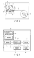
- FIG. 1 is a diagrammatic view showing a radio tag issuing apparatus.
- a printing section 2 for printing on a radio tag
- a radio communicating section 3 for making radio communication with the radio tag.
- the printing section 2 has a thermal head 4 having a larger number of heat generating elements arranged along a width direction and an ink ribbon 5.
- the ink ribbon 5 is pulled out of a ribbon core 6 and, on its way, contacted with the thermal head 4 and finally wound around a ribbon core 7.
- the thermal head 4 is so mounted as to be pressed against a platen roller 8 with the ink ribbon 5 in between.
- a plurality of radio tags are attached to a mount sheet at a predetermined interval.
- the mount sheet 9 is wound around a roll sheet core 10 and it is pulled out from the roll sheet core 10.
- the leading edge of the mount sheet 9 is issued from an issuing section 12 by passing the radio communicating section 3 and platen roller 8.
- the radio communicating section 3 has, within it, an antenna 13 for communicating with the radio tag by wireless.
- FIG. 2 is a block diagram showing a control structure of the radio tag issuing apparatus.
- a controller 21 for controlling each part is provided in the apparatus.
- the controller 21 controls a transmit/receive section 22 in the radio communicating section 3, the printing section 2 for printing on the surface of the radio tag, and a driving section 23 for driving the ribbon cores 6, 7, platen roller 8, conveying roller 11 and roll sheet core 10.
- the radio tag 24 has an antenna 25 and transmit/receive section 26.
- the transmit/receive section 26 includes a storage section for storing an ID and other data. The writing/reading of the information into/out of the radio tag 24 is performed by the transmit/receive section 22 of the radio communicating section 3 through the antenna 13.
- the transmit signal from the transmit/receive section 22 in the radio communicating section 3 is radiated as a radio wave from the antenna 13.
- the radio tag 24 Upon the reception of a transmit signal by the antenna 25 from the transmit/receive section 22, the radio tag 24 allows it to be transferred to the transmit/receive section 26 in it.
- the transmit/receive section 26 takes out the information from the received signal and performs an operation corresponding to this information. Further, the radio tag 24 transmits a signal from the transmit/receive section 26 via the antenna 25 and the transmit signal is sent out to the transmit/receive section 22 in the radio communicating section 3 through the antenna 13.
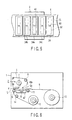
- FIG. 3 is a cross-sectional view showing a plurality of radio tags 24 attached to the mount sheet 9 at a predetermined interval.
- the radio tag 24 is formed on a bonding layer 31, a radio tag inlet 32 is placed on the bonding layer, and a printing layer 33 is formed on a resultant layer.
- the upper surface of the printing layer 33 has a printing surface where printing is made.
- the bonding layer 31 of the radio tag 24 is made of adhesive and can be peeled off the mount sheet 9.
- the radio tag inlet 32 includes an IC chip having the transmit/receive section 26 and the antenna 25.
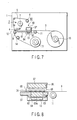
- FIG. 4 is an exploded perspective view showing a structure of the radio communicating section 3.
- a metal member 41 provides a conveying surface and a slit 42 is formed at a central area of the metal member 41.
- Below the metal member 41 is placed a dielectric member 43.
- the dielectric member 43 has a projecting section 43a at the central area which is inserted from below the slit 42.
- the upper surface of the projecting section 43a is flush with the upper surface of the metal member 41. That is, the upper surface of the projecting section 43a provides, like the upper surface of the metal member 41, the conveying surface of the mount sheet 9.
- the dielectric member 43 is made of a first material and the metal member 41 is made of a second material.
- the antenna 13 of the radio communicating section 3 is placed opposite the radio tag being a target of the radio communicating.
- the antenna 13 has a radiating section 45 on a substrate 44.
- the rear surface of the substrate 44 is at a ground plane over its whole surface.
- a core of a coaxial cable 46 is connected to the end of the radiating section 45 and a mesh-like outer conductor of a coaxial cable 46 is connected to the ground plane.
- the antenna 13 is enclosed in a metal case 47 in a state to be opened in a radio tag direction only.
- the coaxial cable 46 is externally extended from a hole 48 in a sidewall of the metal case 47.
- the end of the coaxial cable 46 extended out of the metal case 47 is connected to the transmit/receive section 22.
- As the antenna 13 use is made of a planar patch antenna whose rear end is set to the ground plane. By doing so, the direction in which the directivity of a radiating radio wave is strong can be set to an up direction, that is, to the projecting section 43a of the dielectric member 43. Further, the radio wave can be shielded by the metal case 47 from being radiated both sideways and in a down direction. Thus it is possible to radiate a radio wave only in an up direction.
- FIG. 5 is a plan view showing the mount sheet 9 conveyed on the radio communicating section 3 and having a plurality of radio tags 24 attached at a predetermined intervals to it.
- the radio tag inlet 32 of the respective radio tag 24 has an IC chip 50 and antennas 51, 52 arranged at opposite ends.
- the sizes of the slits 42 as indicated by a dot-dash line in the Figure are so set as to be greater than the outer shape of the antenna section of the radio tag 24 but smaller than the outer shape of the radio tag 24.
- the radio communicating section 3 can make radio communication with the radio tag 24a over the slit 42. That is, the projecting section 43a of the dielectric member 43 is present between the antenna 13 of the radio communicating section 3 and the radio tag being a target of the radio communication.
- the antenna sections of those radio tags 24b, 24c adjacent the radio tag 24a are located on the conveying surface of the metal member 41 of the communicating section 3. That is, the metal member 41 is located between the radio communicating section 3, on one hand, and other radio tags 24b, 24c, on the other, which are adjacent the radio tag 24a with which the radio communicating section 3 makes communication.
- the radio tags 24b, 24c are located on the metal member 41 and there arises a change in the characteristics of the antennas of the radio tags 24b, 24c and an electric power energy generated in the antenna becomes smaller. This fails to start the IC chip 50 and radio communication cannot be made with these tags.
- the radio tag 24a with which radio communication is made is located over the slit 42, that is, over the projecting section 43a serving as the dielectric member, and it is possible to effectively make radio communication even under any feeble electric power from the radio antenna of the radio communicating section 3.
- the conveying surface of the mount sheet 9 has been explained as being formed of a metal member 41
- the present invention is not restricted thereto and use may be made of other than the metal member.
- use may be made of a material different in dielectric constant from the dielectric member 43. If, for example, a material having a relative dielectric constant of, for example, about 3 is used as the dielectric member 43, a material having a relative dielectric constant as high as about 10 may be used as a member providing a conveying surface.
- the present invention is not restricted thereto and, in place of forming any projecting section 43a on the dielectric member 43, a space in the slit 42 is left as such, that is, as an air layer.
- the air layer provides a first material. If, in this case, the slit has a larger width, then the mounting sheet 9 is liable to be caught there and the slit width may be made as near-equal in size as the shape of the antenna section of the radio tag 24.
- the leading edge of a mount section 9 sent out from a roll sheet core 10 is sequentially passed through a conveying roller 11, radio communicating section 3 and platen roller 8 and it is turned back downward past a conveying roller 14 and wound up around a roll sheet core 15.
- the mount sheet 9, after effecting write-and print-operation on the radio tag 24, is wound up around a roll sheet core 15.
- a rolled mount sheet 9 can later be detached from the roll sheet core 15.
- the mount sheet 9 removed from the roll sheet core 15 is carried to a place where person can attach a radio tag 24. There, a radio tag 24 can be removed from the mount sheet 9 and attached to a product, etc.
- the radio communicating section 3 prevents a radio wave which is radiated from the antenna 13 from being radiated both sideways and downward since the radio communicating section 3 has a metal case 47 arranged beneath.
- the radio tag 24 on the mount sheet 9 wound up around the roll sheet core 15 can be prevented from being erroneously read-and write-operated by the radio communicating section 3.
- the radio communicating section 60 has a metal member 61 that defines a conveying surface.
- the metal member 61 has a slit 62, which is located closer to the conveying roller 11 than to the center part of the metal member 61.
- a dielectric member 63 lies below the slit 62 of the metal member 61.
- the dielectric member 63 has a projecting section 63a on the upper surface. The projecting section 63a is inserted in the slit 62 from below.
- the upper surface of the projecting section 63a is flush with the upper surface of the metal member 61. That is, the upper surface of the projecting section 63a together with the upper surface of the metal member 61 provides a conveying surface of the mount sheet 9.
- An antenna 13 is located beneath the projecting section 63a of the dielectric member 63.
- the antenna 13 has a radiating section 45 on a substrate 44 and a coaxial cable 46 is connected to the end of the radiating section 45.
- the antenna 13 is held in a metal case 64 and the coaxial cable 46 is extended outwardly past a hole 65 in a sidewall of the metal case 64.
- the antenna 13 use is made of a planar patch antenna with a reverse surface made at a ground plane. By doing so, the direction in which the directivity of a radiating radio wave is strong is an up direction, that is, it can be oriented toward the projecting section 63a of the dielectric member 63.
- a radio wave radiating both sideways and in a downward direction can be shielded by the metal case 64 and hence it is possible to radiate a radio wave only toward an up direction.
- a metal case 66 lies above the slit 62 of the metal member 61.
- the metal case 66 surrounds the radio tag 24 and opens only to the antenna 13 of the radio communicating section 60.
- the opening of the metal case 66 is opposed to the slit 62.
- the metal case 66 contains a dielectric member 67.
- the metal case 66 has its lateral side greater in length than its front/back side in a mount sheet 9 conveying direction and the metal case 66 has its lateral side's lower end portions located near both the lateral side portions of the metal member 61.
- the metal case 66 has its front/back side' lower end portions, that is, such lower end portions in the mount sheet 9 conveying direction, located at a level higher than the conveying surface provided by the metal member 61 and, in this state, curtain-like metal sheets 68, 69 are attached to the corresponding lateral sidewalls.
- the respective metal sheets 68, 69 are formed of a soft member capable of shielding an electromagnetic wave and these sheets are set to an extent lightly contacting with a surface of a running mount sheet 9. There is no risk that any radio tag 24 attached to the mount sheet 9 will be injured by the metal sheets 68, 69. By doing so, the radio tag 24a is enclosed by the metal case 67 and metal sheets 68, 69 and the electric power of an electromagnetic wave leaking out of the metal decays.
- the radio communicating section 60 can make communication with a radio tag 24a just over the slit 62 and, at this time, the antenna sections of those radio tags 24b, 24c adjacent the radio tag 24a are situated on the conveying surface of the metal member 61 of the radio communicating section 60.
- the radio tag 24b Since the antenna section of the radio tag 24b is situated over the metal member 61, the characteristics of the antenna vary and the electric power generated at the antenna becomes small. Thus, the radio tag 24b fails to start the IC chip. Further, the electric power of an electromagnetic wave supplied to the radio tag 24c decays and hence the radio tag 24c cannot start the IC chip.
- the radio tag 24a with which radio communication is made is located over the slit 62, that is, over the dielectric material, and it is possible to effectively make radio communication under any feeble electric power from the antenna 13 in the radio communicating section 60. Under such electric power, the radio communicating section 60 cannot make radio communication with the radio tags 24b, 24c.
- a metal case 66 with a dielectric member 67 held in it is positioned above the radio tag 24a over the slit 62. If the distance between the radio tag 24a and the top surface of the metal case 66 is made about one half the wave length with which radio communication is made, then it is possible to obtain better characteristics. Since, by doing so, a radio wave radiating from the antenna 13 and directly arriving at the radio tag 24a and a radio wave reflected on the top of the metal case 66 and returned back to the radio tag 24a reinforce each other in a combined fashion, it is possible to make communication with the radio tag 24a in a favorable fashion.
- the upper surface of the radio tag 24a is also shielded by the metal case 66 and metal sheets 68, 69 and it is possible to prevent a radio wave from being radiated to other than a communication-wanted area. By doing so, it is possible to suppress any electric power which might otherwise be consumed by radiation. Since the wavelength of the radio wave depends upon the dielectric constant and, by the use of the dielectric member 67, the wave length of the radio wave is shortened in the dielectric material, the high direction of the metal case 66 can be lowered in comparison with the case where no dielectric member 67 is provided.
- the conveying surface of the mount sheet 9 is provided by the metal member 61
- the present invention is not restricted thereto and use may be made of a member other than the metal one. In short, use may be made of a member which is different is dielectric constant from the dielectric member 6.
- a radio communicating section 70 as shown in FIG. 10 .
- a metal member 71 is used to provide a conveying surface and no slit is formed in the metal member 71.
- a box-like metal case 72 is located as a metal enclosing member with its opening section oriented to the conveying surface side.
- An antenna 73 is located within the metal case 72 and has the same structure as that of the antenna 13 of the previous embodiment. In this connection it is to be noted that its radiating section on a substrate is oriented downward, that is, to the conveying path side.
- the metal case 72 is such that its lateral sidewall side is made larger in length than its front/back sidewall in a mount sheet 9 conveying direction. Further, the metal case 72 is located with its lateral sidewall's lower end portions contacting with those surface portions at and near both ends of the metal member 71.
- the metal case 72 has its front/back side's lower end portions, that is, such lower end portions in the mount sheet 9 conveying direction, located at a higher position than the conveying surface provided by the metal member 71 and curtain-like metal sheets 74, 75 are attached to the lateral sidewalls of the metal case 72.
- the respective metal sheets 74, 75 are formed of a soft member capable of shielding an electromagnetic wave and these sheets are set to an extent lightly contacting with a surface of a running mount sheet 9. Therefore, there is no risk that any radio tag 24 attached to the mount sheet 9 will be injured by the respective metal sheets 74, 75.
- the radio tag 24a In order to make radio communication with the radio tag 24a located beneath the antenna 73, it is necessary to set any electric power of a radio wave radiating from the antenna 73 to be larger than in the previous embodiments. In this case, however, the radio tag 24a is enclosed with the metal case 72 and metal sheets 74, 75 and the electric power of a radio wave leaking out of the metal decays. Thus, there is no risk that, with the adjacent radio tags 24b and 24c, the radio communicating section 70 will make radio communication through the antenna 73.
- the present invention is such that a plurality of radio tags including an IC chip and antenna are conveyed in a state to be attached to a mount sheet and information is sequentially read from, or written into, the respective radio tag on the conveying mount sheet, so that an issuing radio tag can be used by being attached to a product and so on.
Landscapes
- Engineering & Computer Science (AREA)
- Physics & Mathematics (AREA)
- General Physics & Mathematics (AREA)
- Theoretical Computer Science (AREA)
- Artificial Intelligence (AREA)
- Toxicology (AREA)
- Health & Medical Sciences (AREA)
- Computer Vision & Pattern Recognition (AREA)
- Computer Networks & Wireless Communication (AREA)
- Microelectronics & Electronic Packaging (AREA)
- Computer Hardware Design (AREA)
- General Engineering & Computer Science (AREA)
- Electromagnetism (AREA)
- General Health & Medical Sciences (AREA)
- Details Of Aerials (AREA)
- Accessory Devices And Overall Control Thereof (AREA)
- Dot-Matrix Printers And Others (AREA)
- Radar Systems Or Details Thereof (AREA)
- Conveying Record Carriers (AREA)
Applications Claiming Priority (2)
| Application Number | Priority Date | Filing Date | Title |
|---|---|---|---|
| JP2003431403A JP4268514B2 (ja) | 2003-12-25 | 2003-12-25 | 無線タグ発行装置 |
| EP04807769A EP1727077B1 (de) | 2003-12-25 | 2004-12-24 | Funketiketten-ausgabeeinrichtung |
Related Parent Applications (1)
| Application Number | Title | Priority Date | Filing Date |
|---|---|---|---|
| EP04807769.7 Division | 2004-12-24 |
Publications (2)
| Publication Number | Publication Date |
|---|---|
| EP2246809A2 true EP2246809A2 (de) | 2010-11-03 |
| EP2246809A3 EP2246809A3 (de) | 2012-08-29 |
Family
ID=34736432
Family Applications (2)
| Application Number | Title | Priority Date | Filing Date |
|---|---|---|---|
| EP04807769A Expired - Lifetime EP1727077B1 (de) | 2003-12-25 | 2004-12-24 | Funketiketten-ausgabeeinrichtung |
| EP10006645A Withdrawn EP2246809A3 (de) | 2003-12-25 | 2004-12-24 | Funketikettausgabevorrichung |
Family Applications Before (1)
| Application Number | Title | Priority Date | Filing Date |
|---|---|---|---|
| EP04807769A Expired - Lifetime EP1727077B1 (de) | 2003-12-25 | 2004-12-24 | Funketiketten-ausgabeeinrichtung |
Country Status (6)
| Country | Link |
|---|---|
| US (2) | US7439865B2 (de) |
| EP (2) | EP1727077B1 (de) |
| JP (1) | JP4268514B2 (de) |
| CN (1) | CN1764919A (de) |
| DE (1) | DE602004028518D1 (de) |
| WO (1) | WO2005064528A1 (de) |
Families Citing this family (26)
| Publication number | Priority date | Publication date | Assignee | Title |
|---|---|---|---|---|
| TW200530933A (en) * | 2004-03-12 | 2005-09-16 | Renesas Tech Corp | Production process of inlet for electronic tag |
| EP1854637B1 (de) * | 2005-03-03 | 2011-03-02 | Toshiba TEC Kabushiki Kaisha | Drucker und ic-chipkommunikationsvorrichtung |
| JP2006277231A (ja) * | 2005-03-29 | 2006-10-12 | Sato Corp | Rfid用紙のリーダーライター装置 |
| JP4705507B2 (ja) * | 2006-04-17 | 2011-06-22 | 株式会社サトー | Rfidプリンタ |
| JP2007326307A (ja) * | 2006-06-08 | 2007-12-20 | Brother Ind Ltd | タグラベル作成装置 |
| JP2008077283A (ja) * | 2006-09-20 | 2008-04-03 | Dainippon Printing Co Ltd | Icタグ検査装置 |
| JP4234167B2 (ja) | 2006-10-23 | 2009-03-04 | インターナショナル・ビジネス・マシーンズ・コーポレーション | Rfidタグ付物品収容ケースおよびrfidシステム |
| EP1942444B1 (de) * | 2006-11-28 | 2014-03-19 | Brother Kogyo Kabushiki Kaisha | Vorrichtung zur Übermittlung von RFID-Etiketten-Daten |
| US7832952B2 (en) * | 2007-03-21 | 2010-11-16 | Avery Dennison Corporation | High-frequency RFID printer |
| US8790027B2 (en) * | 2007-03-21 | 2014-07-29 | Avery Dennison Corporation | High frequency RFID printer |
| FR2918484B1 (fr) * | 2007-07-04 | 2009-12-04 | Ier | Systeme d'impression comprenant un dispositif de traitement radiofrequence. |
| JP4987840B2 (ja) * | 2008-12-02 | 2012-07-25 | 株式会社東芝 | アンテナ装置および無線通信システム |
| JP5418221B2 (ja) * | 2009-12-29 | 2014-02-19 | シンフォニアテクノロジー株式会社 | Icタグ発行装置 |
| JP5418220B2 (ja) * | 2009-12-29 | 2014-02-19 | シンフォニアテクノロジー株式会社 | インレット検査装置 |
| JP2012103942A (ja) * | 2010-11-11 | 2012-05-31 | Oki Data Corp | Icタグ通信装置 |
| JP5629655B2 (ja) | 2011-07-12 | 2014-11-26 | 東芝テック株式会社 | Rfidタグ発行装置及びrfidタグの位置ずれ検出方法 |
| FR2981770B1 (fr) * | 2011-10-19 | 2013-12-20 | Evolis | Module d'encodage sans contact de carte plastique |
| JP6242248B2 (ja) * | 2014-03-07 | 2017-12-06 | サトーホールディングス株式会社 | Rfidタグ書込み装置 |
| JP6316065B2 (ja) | 2014-03-31 | 2018-04-25 | サトーホールディングス株式会社 | Icタグ発行装置 |
| JP2015194815A (ja) | 2014-03-31 | 2015-11-05 | サトーホールディングス株式会社 | Icタグ発行装置およびシールド板 |
| CN107710500B (zh) * | 2015-06-24 | 2021-02-09 | 日本电信电话株式会社 | 高频线路 |
| JP6842671B2 (ja) * | 2017-07-11 | 2021-03-17 | 株式会社リコー | 画像形成装置 |
| JP6577619B2 (ja) * | 2018-03-14 | 2019-09-18 | サトーホールディングス株式会社 | Icタグ発行装置およびシールド板 |
| JP7266197B2 (ja) * | 2020-03-31 | 2023-04-28 | パナソニックIpマネジメント株式会社 | 通信端末 |
| JP7845896B2 (ja) * | 2022-03-29 | 2026-04-14 | 株式会社サトー | プリンタ、プリンタの制御方法、及びプログラム |
| JP2023146667A (ja) * | 2022-03-29 | 2023-10-12 | サトーホールディングス株式会社 | プリンタ |
Citations (1)
| Publication number | Priority date | Publication date | Assignee | Title |
|---|---|---|---|---|
| JP2003140548A (ja) | 2001-10-31 | 2003-05-16 | Canon Finetech Inc | Rf−id記録機能付き印刷装置 |
Family Cites Families (22)
| Publication number | Priority date | Publication date | Assignee | Title |
|---|---|---|---|---|
| AU662901B2 (en) * | 1991-05-07 | 1995-09-21 | Nippondenso Co. Ltd. | Electronic tag |
| US6104291A (en) * | 1998-01-09 | 2000-08-15 | Intermec Ip Corp. | Method and apparatus for testing RFID tags |
| US6362738B1 (en) * | 1998-04-16 | 2002-03-26 | Motorola, Inc. | Reader for use in a radio frequency identification system and method thereof |
| JPH11308039A (ja) * | 1998-04-23 | 1999-11-05 | Casio Comput Co Ltd | 誘電体共振器アンテナ装置 |
| JP2000187713A (ja) | 1998-08-27 | 2000-07-04 | Nippon Kopatsuku Kk | 商品の運搬用具リサイクルの方法 |
| DE19846295B4 (de) * | 1998-10-07 | 2008-04-24 | Kabushiki Kaisha Sato | Drucker mit einer Einrichtung zum Ansteuern von Transponderchips |
| JP3894688B2 (ja) * | 1999-10-13 | 2007-03-22 | ローム株式会社 | 通信装置 |
| JP4487352B2 (ja) | 1999-11-12 | 2010-06-23 | ソニー株式会社 | 通信端末装置 |
| JP3640297B2 (ja) | 2000-02-14 | 2005-04-20 | 株式会社日立国際電気 | 物品管理用収納棚 |
| US6593853B1 (en) * | 2000-02-18 | 2003-07-15 | Brady Worldwide, Inc. | RFID label printing system |
| JP4545280B2 (ja) * | 2000-05-24 | 2010-09-15 | 株式会社サトー | プリンタ |
| JP2001344570A (ja) * | 2000-06-05 | 2001-12-14 | Japan Servo Co Ltd | 近接型非接触icカード発行装置 |
| JP2001352208A (ja) | 2000-06-07 | 2001-12-21 | Sony Corp | 通信端末装置 |
| JP2002016418A (ja) | 2000-06-27 | 2002-01-18 | Sony Corp | 電子機器 |
| JP2002230499A (ja) * | 2001-02-01 | 2002-08-16 | Dainippon Printing Co Ltd | 非接触icタグ |
| DE10120625A1 (de) * | 2001-04-26 | 2002-11-14 | Muehlbauer Ag | Verfahren und Vorrichtung zum kontaktlosen Testen unbestückter Antennen |
| JP4865151B2 (ja) * | 2001-06-14 | 2012-02-01 | サトーホールディングス株式会社 | プリンタ |
| JP4514374B2 (ja) * | 2001-09-05 | 2010-07-28 | トッパン・フォームズ株式会社 | Rf−idの検査システム |
| EP1487794A1 (de) | 2002-03-14 | 2004-12-22 | Bayer Aktiengesellschaft | Monozyklische aroylpyridinone als entzündungshemmende agentien |
| EP1429417B9 (de) * | 2002-11-21 | 2006-10-25 | Optosys SA | Leser und Transponder in Gehäusen |
| JP3935162B2 (ja) * | 2004-04-28 | 2007-06-20 | 東芝テック株式会社 | Rfタグリーダ/ライタおよびプリンタ |
| CA2576772A1 (en) * | 2004-08-17 | 2006-03-02 | Symbol Technologies, Inc. | Singulation of radio frequency identification (rfid) tags for testing and/or programming |
-
2003
- 2003-12-25 JP JP2003431403A patent/JP4268514B2/ja not_active Expired - Lifetime
-
2004
- 2004-12-24 DE DE602004028518T patent/DE602004028518D1/de not_active Expired - Lifetime
- 2004-12-24 WO PCT/JP2004/019413 patent/WO2005064528A1/ja not_active Ceased
- 2004-12-24 EP EP04807769A patent/EP1727077B1/de not_active Expired - Lifetime
- 2004-12-24 EP EP10006645A patent/EP2246809A3/de not_active Withdrawn
- 2004-12-24 CN CNA2004800078015A patent/CN1764919A/zh active Pending
-
2005
- 2005-08-25 US US11/211,371 patent/US7439865B2/en not_active Ceased
-
2010
- 2010-10-15 US US12/905,277 patent/USRE44631E1/en not_active Expired - Lifetime
Patent Citations (1)
| Publication number | Priority date | Publication date | Assignee | Title |
|---|---|---|---|---|
| JP2003140548A (ja) | 2001-10-31 | 2003-05-16 | Canon Finetech Inc | Rf−id記録機能付き印刷装置 |
Also Published As
| Publication number | Publication date |
|---|---|
| US7439865B2 (en) | 2008-10-21 |
| JP4268514B2 (ja) | 2009-05-27 |
| DE602004028518D1 (de) | 2010-09-16 |
| USRE44631E1 (en) | 2013-12-10 |
| EP2246809A3 (de) | 2012-08-29 |
| JP2005190216A (ja) | 2005-07-14 |
| EP1727077A1 (de) | 2006-11-29 |
| EP1727077B1 (de) | 2010-08-04 |
| US20060001526A1 (en) | 2006-01-05 |
| CN1764919A (zh) | 2006-04-26 |
| WO2005064528A1 (ja) | 2005-07-14 |
| EP1727077A4 (de) | 2007-12-19 |
Similar Documents
| Publication | Publication Date | Title |
|---|---|---|
| USRE44631E1 (en) | Radio tag issuing apparatus and tag issuing method | |
| US11062193B2 (en) | Encoding module, associated encoding element, connector, printer-encoder and access control system | |
| EP1820659B1 (de) | Räumlich selektive UHF-Nahfeldmikrostreifenkupplungsvorrichtung und diese Vorrichtung verwendende RFID-Systeme | |
| US8544740B2 (en) | Apparatus and method for communicating with an RFID transponder | |
| US9391675B2 (en) | Multi-element RFID coupler | |
| US20100039235A1 (en) | Antenna device and apparatus for communicating with RFID tag | |
| US7327265B2 (en) | RF tag reader/writer and printer containing the RF tag reader/writer | |
| EP1660331A2 (de) | Räumlich selektive uhf-nahfeldmikrostreifenkupplungsvorrichtung und diese vorrichtung verwendende rfid-systeme | |
| JP4932859B2 (ja) | 無線タグ発行装置 | |
| JP4565378B2 (ja) | 無線タグ情報通信装置 |
Legal Events
| Date | Code | Title | Description |
|---|---|---|---|
| PUAI | Public reference made under article 153(3) epc to a published international application that has entered the european phase |
Free format text: ORIGINAL CODE: 0009012 |
|
| AC | Divisional application: reference to earlier application |
Ref document number: 1727077 Country of ref document: EP Kind code of ref document: P |
|
| AK | Designated contracting states |
Kind code of ref document: A2 Designated state(s): DE FR GB |
|
| 17P | Request for examination filed |
Effective date: 20101022 |
|
| PUAL | Search report despatched |
Free format text: ORIGINAL CODE: 0009013 |
|
| AK | Designated contracting states |
Kind code of ref document: A3 Designated state(s): DE FR GB |
|
| RIC1 | Information provided on ipc code assigned before grant |
Ipc: G06K 17/00 20060101AFI20120724BHEP Ipc: G06K 7/00 20060101ALI20120724BHEP Ipc: G06K 19/077 20060101ALI20120724BHEP Ipc: G06K 7/10 20060101ALI20120724BHEP Ipc: B41J 29/38 20060101ALI20120724BHEP |
|
| STAA | Information on the status of an ep patent application or granted ep patent |
Free format text: STATUS: THE APPLICATION HAS BEEN WITHDRAWN |
|
| 18W | Application withdrawn |
Effective date: 20130122 |