EP2246831B1 - System und verfahren zur beurteilung gefährlicher präventiver fahrmanöverabsichten - Google Patents
System und verfahren zur beurteilung gefährlicher präventiver fahrmanöverabsichten Download PDFInfo
- Publication number
- EP2246831B1 EP2246831B1 EP09703655.2A EP09703655A EP2246831B1 EP 2246831 B1 EP2246831 B1 EP 2246831B1 EP 09703655 A EP09703655 A EP 09703655A EP 2246831 B1 EP2246831 B1 EP 2246831B1
- Authority
- EP
- European Patent Office
- Prior art keywords
- driver
- data
- angular velocity
- dangerous
- motion
- Prior art date
- Legal status (The legal status is an assumption and is not a legal conclusion. Google has not performed a legal analysis and makes no representation as to the accuracy of the status listed.)
- Active
Links
Images







Classifications
-
- G—PHYSICS
- G08—SIGNALLING
- G08B—SIGNALLING SYSTEMS, e.g. PERSONAL CALLING SYSTEMS; ORDER TELEGRAPHS; ALARM SYSTEMS
- G08B21/00—Alarms responsive to a single specified undesired or abnormal condition and not otherwise provided for
- G08B21/02—Alarms for ensuring the safety of persons
- G08B21/06—Alarms for ensuring the safety of persons indicating a condition of sleep, e.g. anti-dozing alarms
-
- A—HUMAN NECESSITIES
- A61—MEDICAL OR VETERINARY SCIENCE; HYGIENE
- A61B—DIAGNOSIS; SURGERY; IDENTIFICATION
- A61B5/00—Measuring for diagnostic purposes; Identification of persons
- A61B5/103—Measuring devices for testing the shape, pattern, colour, size or movement of the body or parts thereof, for diagnostic purposes
- A61B5/11—Measuring movement of the entire body or parts thereof, e.g. head or hand tremor or mobility of a limb
-
- A—HUMAN NECESSITIES
- A61—MEDICAL OR VETERINARY SCIENCE; HYGIENE
- A61B—DIAGNOSIS; SURGERY; IDENTIFICATION
- A61B5/00—Measuring for diagnostic purposes; Identification of persons
- A61B5/16—Devices for psychotechnics; Testing reaction times ; Devices for evaluating the psychological state
- A61B5/18—Devices for psychotechnics; Testing reaction times ; Devices for evaluating the psychological state for vehicle drivers or machine operators
-
- G—PHYSICS
- G08—SIGNALLING
- G08G—TRAFFIC CONTROL SYSTEMS
- G08G1/00—Traffic control systems for road vehicles
- G08G1/16—Anti-collision systems
- G08G1/165—Anti-collision systems for passive traffic, e.g. including static obstacles, trees
-
- A—HUMAN NECESSITIES
- A61—MEDICAL OR VETERINARY SCIENCE; HYGIENE
- A61B—DIAGNOSIS; SURGERY; IDENTIFICATION
- A61B3/00—Apparatus for testing the eyes; Instruments for examining the eyes
- A61B3/10—Objective types, i.e. instruments for examining the eyes independent of the patients' perceptions or reactions
- A61B3/113—Objective types, i.e. instruments for examining the eyes independent of the patients' perceptions or reactions for determining or recording eye movement
-
- A—HUMAN NECESSITIES
- A61—MEDICAL OR VETERINARY SCIENCE; HYGIENE
- A61B—DIAGNOSIS; SURGERY; IDENTIFICATION
- A61B5/00—Measuring for diagnostic purposes; Identification of persons
- A61B5/68—Arrangements of detecting, measuring or recording means, e.g. sensors, in relation to patient
- A61B5/6801—Arrangements of detecting, measuring or recording means, e.g. sensors, in relation to patient specially adapted to be attached to or worn on the body surface
- A61B5/6802—Sensor mounted on worn items
- A61B5/6803—Head-worn items, e.g. helmets, masks, headphones or goggles
-
- A—HUMAN NECESSITIES
- A61—MEDICAL OR VETERINARY SCIENCE; HYGIENE
- A61B—DIAGNOSIS; SURGERY; IDENTIFICATION
- A61B5/00—Measuring for diagnostic purposes; Identification of persons
- A61B5/68—Arrangements of detecting, measuring or recording means, e.g. sensors, in relation to patient
- A61B5/6801—Arrangements of detecting, measuring or recording means, e.g. sensors, in relation to patient specially adapted to be attached to or worn on the body surface
- A61B5/6813—Specially adapted to be attached to a specific body part
- A61B5/6829—Foot or ankle
-
- A—HUMAN NECESSITIES
- A61—MEDICAL OR VETERINARY SCIENCE; HYGIENE
- A61B—DIAGNOSIS; SURGERY; IDENTIFICATION
- A61B5/00—Measuring for diagnostic purposes; Identification of persons
- A61B5/68—Arrangements of detecting, measuring or recording means, e.g. sensors, in relation to patient
- A61B5/6887—Arrangements of detecting, measuring or recording means, e.g. sensors, in relation to patient mounted on external non-worn devices, e.g. non-medical devices
- A61B5/6893—Cars
Definitions
- the present invention relates to a dangerous drive preventive intention judging system and a dangerous drive preventive intention judging method. More specifically, the present invention relates to a system and method of judging a dangerous drive preventive intention which are for judging a dangerous drive preventive intention of a driver when a motor vehicle approaches a dangerous place.
- Patent Document 1 Japanese Patent Application Laid-Open No. 2002-331850 [B60K 28/06, A61B 3/113, 5/18, B60K 28/16, B60R 21/00]
- a technique of predicting a driving motion intention is disclosed.
- a taxicab business world takes various measures to reduce accidents by taxi drivers at the present.
- a reeducation course of driving aimed at a taxi driver who caused an accident is especially frequently performed.
- the reeducation course is just ex post measures, and the effect of the course is reduced with time. It is conceivable that the taxi driver who is considered to have a high probability of causing an accident is preselected, and is made to take the reeducation course, but as a selecting means therefor, it is merely possible to depend on a self-assessed type questionnaire test, such as a driving aptitude test in reality.
- braking stance a person who moves the foot to the brake pedal before entering the intersection and prepares for emergency
- US 2006/195241 A1 discloses a vehicle information notification device which is able to evaluate the right-and-left safe-condition check state of a driver according to the geometric form of an intersection.
- Another object of the present invention is to provide a system and method of judging a dangerous drive preventive intention capable of judging a right-and-left checking motion and a braking stance without placing a significant burden on a driver.
- Another object of the present invention is to provide a system and method of judging a dangerous drive preventive intention capable of quantitatively measuring a dangerous drive preventive intention of a driver.
- the present invention employs following features in order to solve the above-described problems. It should be noted that reference numerals and the supplements inside the parentheses show one example of a corresponding relationship with the embodiments described later for easy understanding of the present invention, and do not limit the present invention.
- a first embodiment is a system of judging a dangerous drive preventive intention for judging a dangerous drive preventive intention of a driver of a motor vehicle with respect to a dangerous place, and comprises a first movement detector which detects a movement of a head of the driver; a position detector which detects position data of the motor vehicle; a first judger which judges whether or not a visually checking motion is performed on the basis of the movement data detected by the first movement detector when the motor vehicle approaches the dangerous place on the basis of the position data detected by the position detector; and an alarmer which issues an alarm when the first judger judges that a visually checking motion was not performed.
- a dangerous drive preventive intention judging system judges whether or not a driver performs a visually checking motion in order to judge a dangerous drive preventive intention of a driver of a vehicle with respect to a dangerous place, such as an unsignalized intersection, an accident-prone place, for example.
- a first movement detector (14) is for detecting a movement of a head of the driver.
- the first movement detector may be an angular velocity sensor, an acceleration sensor, or the like. In a case that an angular velocity sensor is applied, the angular velocity sensor is attached to a head of the driver, for example, by being attached to a cap (26) of the driver, and detects a rotation of the head of the driver.
- a position detector (12, 18, S1) detects position data of the motor vehicle.
- the position detector is a GPS receiver, for example, and detects coordinates (latitude, longitude, altitude) of a current position of the motor vehicle.
- a first judger (12, S13, S41-S47) judges whether or not a visually checking motion is performed on the basis of the movement data detected by the first movement detector when the motor vehicle approaches the dangerous place on the basis of the position data detected by the position detector.
- information as to a position of the dangerous place is previously stored in a memory (20) as map data (road data), for example, and on the basis of the map data and the position data, it is determined whether or not the motor vehicle approaches the dangerous place.
- map data road data
- an angular velocity sensor is applied as a first movement detector, angular velocity data is detected as movement data, and therefore, it is possible to judge whether or not a visually checking motion is performed on the basis of the angular velocity data.
- an alarmer (12, 22, S17-S21) issues an alarm when the first judger judges that a visually checking motion was not performed. The alarm is performed by a sound output, an image display, a vibration output, or the like.
- the movement of the head of the driver is detected by using the motion detector, so that it is possible to measure a visually checking motion of the driver without placing a burden on the driver, and it is possible to easily judge whether or not a visually checking motion is performed when the vehicle approaches the dangerous place. Then, when a visually checking motion was not performed even if the vehicle approaches the dangerous place, an alarm can be output, thus, it is possible to urge the driver to perform a visually checking motion and heighten a dangerous drive preventive intention of the driver.
- a second embodiment is according to the first embodiment, and further comprises a first video image data saver which saves video image data of at least one of an in-vehicle video image and an out-vehicle video image of the motor vehicle when the first judger judges that a visually checking motion was not performed.
- a shooter (video camera 36a, 36b) capable of shooting at least one of an in-vehicle video image and an out-vehicle video image of the motor vehicle is provided, and a first video image data saver (12, 22) saves video image data of the video shot by the shooter.
- the embodiment invention by reproducing video image data saved by the first video image data saver, it is possible to show the driver a situation (video image) in which a necessary visually checking motion was not performed, and therefore, it is possible to more strongly urge the driver to perform a visually checking motion and heighten a dangerous drive preventive intention of the driver.
- a third embodiment is according to the first or the second embodiment, and further comprises a first sound data saver which saves sound data of at least an in-vehicle sound of the motor vehicle when the first judger judges that a visually checking motion was not performed.
- a sound capturer (microphone 38) capturing sound data of at least an in-vehicle sound of the motor is provided, and a first sound data saver (12, S22) saves sound data of the sound captured by the capturer.
- the third embodiment by producing the sound data saved by the first sound data saver, it is possible to show the relevant driver a situation (sound) when a necessary visually checking motion was not performed, and therefore, it is possible to more strongly urge the driver to perform a visually checking motion and heighten a dangerous drive preventive intention of the driver.
- a fourth embodiment is a dangerous drive preventive intention judging system according to the first embodiment, and further comprises: a second movement detector which detects a motion of a right toe of the driver; and a second judger which judges whether or not a braking stance is taken on the basis of movement data detected by the second movement detector when it is determined that the motor vehicle approaches the dangerous place on the basis of the position data detected by the position detector; wherein the alarmer issues an alarm when the second judger judges that a braking stance was not taken.
- a second movement detector (16) is for detecting a motion of a right toe of the driver.
- the second movement detector is an angular velocity sensor.
- the angular velocity sensor is attached to the right toe of the driver with which the driver performs accelerating and braking operations, and detects a rotation of the right toe of the driver. If the driver moves the right foot to a side of the brake pedal (32), the angular velocity to the left direction is detected, and if the driver moves the right foot to the side of the accelerator pedal (30), the angular velocity to the right direction is detected.
- a second judger (12, S15, S61-S75) judges whether or not a braking stance is taken on the basis of movement data detected by the second movement detector when it is determined that the motor vehicle approaches the dangerous place. If an angular velocity sensor is applied as a second movement detector, angular velocity data is detected as movement data, and therefore, whether or not a braking stance is taken is judged on the basis of the angular velocity data. Then, an alarmer outputs an alarm when it is judged that a braking stance was not performed as well.
- the movement of the right toe of the driver is further detected by using the movement detector, and therefore, it is possible to measure a braking stance of the driver without placing a burden on the driver, and it is possible to easily judge whether or not a braking stance is taken when the vehicle approaches the dangerous place. Moreover, when a braking stance is not taken, it is possible to issue an alarm to the driver, so that it is possible to urge the driver to take a braking stance by releasing the right foot from the accelerator and take a braking stance and heighten a dangerous drive preventive intention of the driver.
- a fifth embodiment is a dangerous drive preventive intention judging system judging a dangerous drive preventive intention of a driver of a motor vehicle with respect to a dangerous place, comprising: a second movement detector which detects a movement of a right toe of the driver; a position detector which detects position data of the motor vehicle; a second judger which judges whether or not a braking stance is taken on the basis of movement data detected by the second movement detector when it is determined that the motor vehicle approaches the dangerous place on the basis of the position data detected by the position detector; and an alarmer which issues an alarm when the second judger judges that a braking stance was not taken.
- a dangerous drive preventive intention judging system judges whether or not a driver takes a braking stance in order to judge a dangerous drive preventive intention of a driver of a vehicle with respect to a dangerous place, such as an unsignalized intersection, an accident-prone place, for example.
- a second movement detector (16) is for detecting a movement of a right toe of the driver.
- the second movement detector may be an angular velocity sensor, an acceleration sensor, or the like. In a case that an angular velocity sensor is applied, the angular velocity sensor is attached to the right toe of the driver with which the driver performs accelerating and braking operations, and detects a rotation of the right toe of the driver.
- a position detector (12, 18, S1) detects position data of the motor vehicle.
- the position detector is a GPS receiver, for example, and detects coordinates (latitude, longitude, altitude) of a current position of a motor vehicle.
- a second judger (12, S15, S61-S75) judges whether or not a braking stance is taken on the basis of movement data detected by the second movement detector when it is determined that the motor vehicle approaches the dangerous place.
- information as to a position of the dangerous place is previously stored in the memory (20) as map data (road data), for example, and on the basis of the map data and the position data, it is determined whether or not the motor vehicle approaches the dangerous place.
- An angular velocity sensor is applied as a second movement detector, angular velocity data is detected as movement data, and therefore, on the basis of the angular velocity data, whether or not a braking stance is taken is judged.
- An alarmer (12, 22, S17-S21) issues an alarm when the second judger judges that a braking stance was not performed. The alarm is performed by a sound output, an image display, a vibration output or the like.
- the movement of the right toe of the driver is further detected by using the movement detector, and therefore, it is possible to measure a braking stance of the driver without placing a burden on the driver, and it is possible to easily judge whether or not a braking stance is taken when the vehicle approaches the dangerous place. Moreover, when a braking stance is not taken, it is possible to output an alarm to the driver, so that it is possible to urge the driver to take a braking stance by releasing the right foot from the accelerator and take a braking stance, and heighten a dangerous drive preventive intention of the driver.
- a sixth embodiment is according to the fifth embodiment, and further comprises a second video image data saver which saves video image data of at least one of an in-vehicle video image and an out-vehicle video image of the motor vehicle when the second judger judges that a braking stance was not taken.
- a shooter (video camera 36a, 36b) capable of shooting at least one of an in-vehicle video image and an out-vehicle video image of the motor vehicle is provided, and a second video image data saver (12, S22) saves video image data of the video shot by the shooter.
- the sixth embodiment by reproducing the video image data saved by the second video image data saver, it is possible to show the driver a situation (video) in which a necessary braking stance was not taken, and it is possible to more strongly urge the driver to take a braking stance and heighten a dangerous drive preventive intention of the driver.
- a seventh embodiment is according to the fifth or the sixth embodiment, and further comprising a second sound data saver which saves sound data of at least an in-vehicle sound of the motor vehicle when the second judger judges that a braking stance was not taken.
- a sound capturer (microphone 38) capturing sound data of at least an in-vehicle sound of the motor is provided, and a second sound data saver (12, S22) saves sound data of the sound captured by the sound capturer.
- the seventh embodiment by reproducing the sound data saved by the second sound data saver, it is possible to show the drive a situation (sound) when a necessary braking stance was not taken, and therefore, it is possible to more strongly urge the driver to take a braking stance and heighten a dangerous drive preventive intention of the driver.
- An eighth embodiment is a dangerous drive preventive intention judging system judging a dangerous drive preventive intention of a driver of a motor vehicle with respect to a dangerous place, comprising: a first movement detector which detects a movement of a head of the driver; a position detector which detects position data of the motor vehicle; a first judger which determines whether or not a visually checking motion is performed on the basis of movement data detected by the first movement detector when it is determined that the motor vehicle approaches the dangerous place on the basis of the position data detected by the position detector; and a recorder which records a judgment result by the first judger.
- a dangerous drive preventive intention judging system (10) comprises a first movement detector, a position detector, and a first judger similar to the above-described first invention in order to judge a dangerous drive preventive intention of a driver with respect to a dangerous place. That is, the dangerous drive preventive system can judge whether or not the driver performs a visually checking motion when the motor vehicle approaches the dangerous place.
- the dangerous drive preventive intention judging system comprises a recorder (12, 24, S23), and the recorder records a judgment result by the first judger.
- the movement of the head of the driver is detected by using the motion detector, so that it is possible to measure a visually checking motion of the driver without placing a burden on the driver, and it is possible to easily judge whether or not a visually checking motion is performed when the vehicle approaches the dangerous place. Moreover, a judgment result of the visually checking motion with respect to the dangerous place can be recorded. Thus, it is possible to quantitatively measure the dangerous drive preventive intention of the driver and evaluate a dangerous drive preventive intention of the driver.
- a ninth embodiment is a dangerous drive preventive intention judging system according to the eighth embodiment, further comprising: a second movement detector which detects a movement of a right toe of the driver; and a second judger judges whether or not a braking stance is taken on the basis of movement data detected by the second movement detector when it is determined that the motor vehicle approaches the dangerous place on the basis of the position data detected by the position detector; wherein the recorder further records a judgment result by the second judger.
- a dangerous drive preventive intention judging system further comprising a second movement detector and second judger similar to the above-described second invention. That is, the dangerous drive preventive intention judging system can further judge whether or not a braking stance is taken when the motor vehicle approaches the dangerous place.
- the recorder further records a judgment result by the second judger.
- the movement of the right toe of the driver is detected by using the movement detector, and therefore, it is possible to further measure a braking stance of the driver without placing a burden on the driver, and it is possible to easily judge whether or not a braking stance is taken when the vehicle aproaches the dangerous place. Then, judgment results of the visually checking motion and the braking stance of the driver with respect to the dangerous place can be recorded. Thus, it is possible to quantitatively measure the dangerous drive preventive intention based on both of the visually checking motion and the braking stance, and evaluate the dangerous drive preventive intention of the driver.
- a tenth embodiment is a dangerous drive preventive intention judging system judging a dangerous drive preventive intention of a driver of a motor vehicle with respect to a dangerous place, comprising: a second movement detector which detects a movement of a right toe of the driver; a position detector which detects position data of the motor vehicle; a second judger which judges whether or not a braking stance is taken on the basis of movement data detected by the second movement detector when it is determined that the motor vehicle approaches the dangerous place on the basis of the position data detected by the position detector; and a recorder which records a judgment result of the second judger.
- a dangerous drive preventive intention judging system (10) comprises a second movement detector, a position detector, and a second judger similar to the above-described fourth embodiment That is, the dangerous drive preventive intention judging system can judge whether or not the driver takes a braking stance when the motor vehicle approaches the dangerous place.
- the tenth invention comprises a recorder (12, 24, S23), and the recorder records a judgment result by the second judger.
- the movement of the right toe of the driver is further detected by using the movement detector, and therefore, it is possible to measure a braking stance of the driver without placing a burden on the driver, and it is possible to easily judge whether or not a braking stance is taken when the vehicle approaches the dangerous place. Then, it is possible to record a determination result of the braking stance with respect to the dangerous place. Thus, it is possible to quantitatively measure a dangerous drive preventive intention of the driver and evaluate the dangerous drive preventive intention of the driver.
- An eleventh embodiment is dangerous drive preventive intention judging system judging a dangerous drive preventive intention of a driver of a motor vehicle with respect to a dangerous place, comprising: a memory which stores movement data detected and recorded by a first movement detector detecting a movement of a head of the driver and position data of the motor vehicle detected and recorded by a position detecting device; a first judger which judges whether or not a visually checking motion is performed when a position of the motor vehicle approaches the dangerous place on the basis of the movement data by the first movement detector and the position data of the motor vehicle; and a result outputter which outputs a judgment result by the first judger.
- a dangerous drive preventive intention judging system 10 performs an ex post analysis on the data recorded during driving and judges whether or not the driver performs a visually checking motion.
- a memory (12, 24) stores recording data including movement data of the head of the driver and position data of the motor vehicle.
- the movement data of the head is data detected and recorded by a first movement detector (14) detecting a movement of the head of the driver.
- the first movement detector may be an angular velocity sensor, an acceleration sensor or the like.
- the angular velocity sensor If the angular velocity sensor is applied, a rotation of the head of the driver during driving is detected by the angular velocity sensor, and angular velocity data is recorded as movement data, and thus, in this memory, the angular velocity data of the head is stored. Furthermore, the position data of the motor vehicle is data detected and recorded by a position detecting device (18), such as a GPS receiver, for example.
- the first judger (12, S109) judges whether or not a visually checking motion is performed when a position of the motor vehicle approaches the dangerous place on the basis of the movement data by the first movement detector and the position data of the motor vehicle.
- map data road data
- the visually checking motion of the driver can be judged.
- a result outputter (12, S121) outputs a judgment result by the first judger.
- the judgment result data may be output by a file, may be displayed on the display, or an evaluation of the judgment result may be output.
- the eleventh embodiment it is possible to perform a visually checking motion with respect to the dangerous place ex post facto on the basis of the recorded movement data of the head, the recorded position data of the motor vehicle, etc., and it is possible to quantitatively measure and evaluate the dangerous drive preventive intention of the driver.
- a twelfth embodiment is a dangerous drive preventive intention judging system according to the eleventh embodiment wherein the memory further stores movement data detected and stored by a second movement detector detecting a movement of a right toe of the driver, further comprising: a second judger which judges whether or not a braking stance is taken when a position of the motor vehicle approaches the dangerous place on the basis of the movement data by the second movement detector and position data of the motor vehicle, and the result outputter outputs judgment results by the first judger and the second judger.
- the memory further stores movement data of the right toe of the driver.
- the movement data of the right toe is data detected and stored by a second movement detector detecting a movement of a right toe of the driver.
- the second movement detector may be an angular velocity sensor, an acceleration sensor or the like. In a case that the angular velocity sensor is applied, a rotation of the head of the driver during driving is detected by the angular velocity sensor, and angular velocity data is recorded as movement data, and thus, in the memory, the angular velocity data of the right toe is stored.
- a second judger (12, S113) judges whether or not a braking stance is taken when a position of the motor vehicle approaches the dangerous place on the basis of the movement data of the right toe and position data of the motor vehicle. By analyzing the movement data of the right toe, it is possible to judge whether or not the driver takes a braking stance when the motor vehicle approaches the dangerous place. Then, the result outputter outputs judgment results by the first judger and the second judger.
- the twelfth embodiment it is possible to judge a visually checking motion and a braking stance with respect to the dangerous place ex post facto on the basis of the recorded movement data of the head and the right toe of the driver, the position data of the motor vehicle, etc., and it is possible to quantitatively measure and evaluate the dangerous drive preventive intention of the driver on the basis of the visually checking motion and the braking stance by the driver.
- a thirteenth embodiment is a dangerous drive preventive intention judging system judging dangerous drive preventive intention of a driver of a motor vehicle with respect to a dangerous place, comprising: a memory which stores movement data detected and recorded by a second movement detector detecting a movement of a right toe of the driver, and position data of the motor vehicle detected and recorded by a position detecting device; a second judger which judges a braking stance is taken when a position of the motor vehicle approaches the dangerous place on the basis of the movement data by the second movement detector and the position data of the motor vehicle; and a result outputter which outputs a judgment result by the second judger.
- a dangerous drive preventive intention judging system 10 performs an ex post analysis on the data recorded during driving and judges whether or not the driver performs a visually checking motion.
- a memory (12, 24) stores recording data including movement data of the right toe of the driver, and position data of the motor vehicle.
- the movement data of the right toe is data detected and recorded by a second movement detector (16) detecting a movement of the right toe of the driver.
- the second movement detector may be an angular velocity sensor, an acceleration sensor or the like.
- the position data of the motor vehicle is detected and recorded by a position detecting device (18), such as a GPS receiver, for example.
- a second judger (12, S113) judges whether or not a braking stance is taken when a position of the motor vehicle approaches the dangerous place on the basis of the movement data of the right toe and the position data of the motor vehicle.
- information as to a position of the dangerous place is previously stored in a memory (12, 20) as map data (road data), for example, and on the basis of the map data and the position data, it is determined whether or not the motor vehicle approaches the dangerous place. Then, by analyzing the movement data of the right toe, whether or not a braking stance is taken when the motor vehicle approaches the dangerous place can be judged.
- a result outputter (12, S121) outputs a judgment result by the second judger.
- the judgment result data may be output by a file, may be displayed on the display, or an evaluation of the judgment result may be output.
- the thirteenth embodiment it is possible judge a braking stance with respect to the dangerous place ex post facto on the basis of the recorded movement data of the right toe, the recorded position data of the motor vehicle, etc., and it is possible to quantitatively measure and evaluate the dangerous drive preventive intention of the driver.
- a fourteenth embodiment is a dangerous drive preventive intention judging system according to any one of the first to thirteenth embodiments, wherein the movement detector is an angular velocity sensor.
- an angular velocity sensor is applied as a movement detector, and by the angular velocity sensor, the movements of the head and the right toe of the driver are detected. Accordingly, it is possible to measure a visually checking motion and a braking stance of the driver without placing a burden on the driver, and it is possible to easily judge whether a visually checking motion is performed and a braking stance is taken when the vehicle approaches the dangerous place.
- a fifteenth embodiment is a dangerous drive preventive intention judging method judging a dangerous drive preventive intention of a driver of a motor vehicle with respect to a dangerous place, including steps of: (a) recording movement data detected by a first movement detector detecting a movement of a head of the driver; and (b) judging whether or not a visually checking motion is performed when the motor vehicle approaches the dangerous place on the basis of the movement data by the first movement detector.
- the movement data of the first movement detector detecting a movement of the head of the driver is recorded, and on the basis of the movement data, the visually checking motion is judged, and therefore, it is possible to easily judge the visually checking motion without placing a burden on the driver.
- a sixteenth embodiment is dangerous drive preventive intention judging method judging a dangerous drive preventive intention of a driver of a motor vehicle with respect to a dangerous place, including steps of: (a) recording movement data detected by a second movement detector detecting a movement of a right toe of the driver; and (b) judging whether or not a braking stance is taken when the motor vehicle approaches the dangerous place on the basis of the movement data by the second movement detector.
- the movement data of the second movement detector detecting the movement of the right toe of the driver is recorded, and on the basis of the movement data, a braking stance is judged, and therefore, it is possible to easily judge a braking stance without placing a burden on the driver.
- a seventeenth embodiment is a dangerous drive preventive intention judging method according to any one of the fifteenth to sixteenth embodiments wherein the movement detector is an angular velocity sensor.
- the angular velocity sensor is applied, and therefore, it is possible to measure a visually checking motion and a braking stance of the driver without placing a burden on the driver.
- An eighteenth embodiment is a dangerous drive preventive intention judging system judging a dangerous drive preventive intention of a driver of a motor vehicle with respect to a dangerous place, comprising: a motion detector which detects a motion of the driver and outputs motion data; a position detector which detects position data of the motor vehicle; a judger which judges whether or not a danger preventing motion is performed on the basis of the motion data by the motion detector when it is determined that the motor vehicle approaches the dangerous place on the basis of the position data detected by the position detector; and a video image data storage which stores video image data of at least one of an in-vehicle video image and an out-vehicle video image of the motor vehicle when the judger judges that a danger preventing motion was not performed.
- a dangerous drive preventive intention judging system judges whether or not a driver performs danger averting or preventing motion in order to judge a dangerous drive preventive intention of a driver of a vehicle with respect to a dangerous place, such as an unsignalized intersection, an accident-prone place, for example.
- a motion detector (14, 16) detects a motion of the driver by detecting a movement of the head of the driver and a movement of the right foot of the driver.
- the motion detector may be an angular velocity sensor, an acceleration sensor, or the like.
- the angular velocity sensor is applied to detect the movement of the head of the driver as a motion of the driver
- the angular velocity sensor is attached to the head of the driver by being attached to a cap (26) of the driver and detects a rotation of the head of the driver. If the driver turns to a left direction in order to perform a visual check, a angular velocity to the left direction is detected, and if the driver turns to a right direction, a angular velocity to the right direction is detected. Accordingly, by detecting a rotation of the head by utilizing the angular velocity sensor, it is possible to detect the motion of the driver.
- the angular velocity sensor is applied to detect the movement of the right foot of the driver as a motion of the driver
- the angular velocity sensor is attached to the right toe of the driver with which the driver performs accelerating and braking operations, and detects a rotation of the right toe of the driver. If the driver moves the right foot to a side of the brake pedal (32), the angular velocity to the left direction is detected, and if the driver moves the right foot to the side of the accelerator pedal (30), the angular velocity to the right direction is detected.
- a rotation of the right toe by utilizing the angular velocity sensor, it is possible to measure whether or not the driver moves the right foot to the side of the brake pedal, that is, whether or not a braking stance is taken.
- a position detector (12, 18, S1) detects position data of the motor vehicle.
- the position detector is a GPS receiver, for example, and detects coordinates (latitude, longitude, altitude) of a current position of the motor vehicle.
- a judger (12, S13, S41-S47:12, S15, S61-S75) determines whether or not a danger prevention or an averting motion is performed on the basis of the motion data detected by the motion detector when it is determined that the motor vehicle approaches the dangerous place on the basis of the position data.
- information as to a position of the dangerous place is previously stored in a memory (20) as map data (road data), for example, and on the basis of the map data and the position data, it is determined whether or not the motor vehicle approaches the dangerous place.
- a shooter (video camera 36a, 36b) capable of shooting at least one of an in-vehicle video image and an out-vehicle video image of the motor vehicle is provided, and if the judger judges that a danger prevention or an averting motion was not performed, a video image data storage(12, S22) stores video image data of the video shot by the shooter.
- the eighteenth embodiment by reproducing the video image data stored by the video image data storage, it is possible to show the driver a situation (video) in which a necessary danger preventing (averting) motion was not performed, and it is possible to more strongly urge the driver to perform a danger preventing (averting) motion and heighten a dangerous drive preventive intention of the driver.
- a nineteenth embodiment is according to the eighteenth embodiment, further comprising an alarmer which issues an alarm when the judger judges that a danger preventing motion was not performed.
- an alarmer (12, 22, S17-S21) outputs an alarm when the judger judges that a danger preventing motion was not performed.
- the alarm is performed by a sound output, an image display, a vibration output, or the like.
- the nineteenth embodiment even if the vehicle approaches the dangerous place, a danger prevention or an averting motion is not performed, an alarm can be generated, and therefore, it is possible to urge the driver to perform a danger prevention or an averting motion and heighten the dangerous drive preventive intention of the driver.
- a twentieth embodiment is a dangerous drive preventive intention judging system judging a dangerous drive preventive intention of a driver of a motor vehicle with respect to a dangerous place, further comprising: a motion detector which detects a motion of the driver and outputs motion data; a position detector which detects position data of the motor vehicle; a judger which judges whether or not a danger preventing motion is performed on the basis of the motion data by the motion detector when it is determined that the motor vehicle approaches the dangerous place on the basis of the position data detected by the position detector; and an alarmer which issues an alarm when the judger judges that a danger preventing motion was not performed.
- a dangerous drive preventive intention judging system judges whether or not a driver performs danger averting or preventing motion in order to judge a dangerous drive preventive intention of a driver of a vehicle with respect to a dangerous place, such as an unsignalized intersection, an accident-prone place, for example.
- a motion detector (14, 16) detects a motion of the driver by detecting a movement of the head of the driver and a movement of the right foot of the driver.
- the motion detector may be an angular velocity sensor, an acceleration sensor, or the like.
- the angular velocity sensor is applied to detect a movement of the head of the driver as a motion of the driver
- the angular velocity sensor is attached to the head of the driver by being attached to a cap (26) of the driver and detects a rotation of the head of the driver. If the driver turns to a left direction in order to perform a visual check, an angular velocity to the left direction is detected, and if the driver turns to a right direction, a angular velocity to the right direction is detected. Accordingly, by detecting a rotation of the head by utilizing the angular velocity sensor, it is possible to detect a motion of the driver.
- the angular velocity sensor is applied to detect a movement of the right foot of the driver as a motion of the driver
- the angular velocity sensor is attached to the right toe of the driver with which the driver performs accelerating and braking operations, and detects a rotation of the right toe of the driver. If the driver moves the right foot to a side of the brake pedal (32), the angular velocity to the left direction is detected, and if the driver moves the right foot to the side of the accelerator pedal (30), the angular velocity to the right direction is detected.
- a rotation of the right toe by utilizing the angular velocity sensor, it is possible to measure whether or not the driver moves the right foot to the side of the brake pedal, that is, whether or not a braking stance is taken.
- a position detector (12, 18, S1) detects position data of the motor vehicle.
- the position detector is a GPS receiver, for example, and detects coordinates (latitude, longitude, altitude) of a current position of the motor vehicle.
- a judger (12, S13, S41-S47:12, S15, S61-S75) judges whether or not a danger prevention or an averting motion is performed on the basis of the motion data detected by the motion detector when it is determined that the motor vehicle approaches the dangerous place on the basis of the position data.
- information as to a position of the dangerous place is previously stored in a memory (20) as map data (road data), for example, and it is determined whether or not the motor vehicle approaches the dangerous place on the basis of the map data and the position data.
- an alarmer (12, 22, S17-S21) outputs an alarm.
- the alarm is performed by a sound output, an image display, a vibration output, or the like.
- a motion of the driver is detected by utilizing the motion detector, and therefore, it is possible to determine whether or not a danger prevention or an averting motion is performed when the motor vehicle approaches the dangerous place. Then, even if the vehicle approaches the dangerous place, a danger prevention or an averting motion was not performed, an alarm can be generated, and therefore, it is possible to urge the driver to perform a danger prevention or an averting motion, and heighten the dangerous drive preventive intention of the driver.
- a motion of the driver is detected, and therefore, it is possible to judge whether or not a danger prevention or an averting motion is performed when the vehicle approaches the dangerous place. Then, even if the vehicle approaches the dangerous place, a danger prevention or an averting motion was not performed, an alarm can be generated, and therefore, it is possible to urge the driver to perform a danger prevention or an averting motion, and heighten the dangerous drive preventive intention of the driver.
- a movement of the head of the driver is detected by utilizing a movement detector, it is possible to easily judge whether or not a visually checking motion was performed when the vehicle approaches the dangerous place.
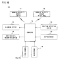
- a dangerous drive preventive intention judging system (hereinafter simply referred to as "system") 10 according to this embodiment is for judging a dangerous drive preventive intention of a driver by judging whether or not the driver performs right and left visual checks and takes a braking stance when a motor vehicle approaches a dangerous place, and includes a computer 12, angular velocity sensors 14, 16, a position detecting device 18, a map database 20, an alarming device 22 and a driving data recording device 24.
- the computer 12 is for executing an overall control of the system 10, and is a personal computer, a portable information terminal, etc. but may be a computer of an electronic control unit of the motor vehicle or a computer of a car navigation system.
- the computer 12 is, although illustration is omitted, provided with a CPU, a ROM, a RAM, a communication device, etc.
- the ROM previously stores a control program and data.
- the RAM is used as a work memory and a buffer memory, and temporarily stores generated data and acquired data, etc.
- the communication device transmits and receives data with respective devices such as angular velocity sensors 14, 16, etc. to be connected to this computer 12.
- the angular velocity sensor 14 is applied for detecting a movement of a head of the driver, and the angular velocity sensor 16 is applied for detecting a movement of a right toe of the driver.
- the angular velocity sensor 14 is for detecting a right and left visually checking motion of the driver, and the angular velocity sensor 16 is for detecting a braking stance of the driver, and therefore, as angular velocity sensors 14 and 16, one capable of detecting at least one-axis angular velocity may be used. Accordingly, a one-axis angular velocity sensor, a two-axis angular velocity sensor or a three-axis angular velocity sensor can be used.
- each of the angular velocity sensors 14, 16 detects an angular velocity about a predetermined axis at a predetermined cycle. Furthermore, each of the angular velocity sensors 14, 16 has a communication function, and transmits the detected angular velocity data to the computer 12 for each predetermined time interval or at a predetermined timing. Furthermore, in this embodiment, each of the angular velocity sensors 14, 16 transmits and receives data with the computer 12 by a short distance wireless communication such as a Bluetooth (registered trademark). Additionally, in another embodiment, each of the angular velocity sensors 14, 16 may be connected to the computer 12 by wire, but may be preferably connected in a wireless manner so as not to prevent the driver from driving the motor vehicle.
- the angular velocity sensor 14 is attached to the head of the driver in order to detect a visually checking motion by the driver.
- a visually checking motion by the driver.
- the driver performs a right and left visually checking motion, not only the eyeballs but also the head are generally moved more or less.
- changes in a gazing direction can be estimated without placing a significant burden on the driver.
- a cap 26 is used as shown in Figure 2 in this embodiment, and the angular velocity sensor 14 is attached to a brim of the cap 26, for example.
- Figure 2 shows a situation that the cap 26 is viewed from above.
- the angular velocity sensor 14 is attached to the cap 26 so as to detect an angular velocity in correspondence with a rotation about at least an axis of a vertical direction. If the driver puts on the cap 26 attached with the angular velocity sensor 14, angular velocity data in correspondence with a rotation (turn) of the head of the driver in a horizontal direction can be measured, that is, a rotation of the head of the driver. That is, a visually checking motion can be detected and measured.
- a counterclockwise rotation is set to a positive
- a clockwise rotation is set to a negative direction in Figure 2 . If the driver who puts on the cap 26 turns to the left, positive angular velocity data is detected, and if the driver turns to the right, the negative angular velocity data is detected. Thus, by analyzing the velocity data of the angular velocity sensor 14, the computer 12 judges whether or not the driver turns his or her head right or left, that is, whether or not a right or left visually checking motion is performed.
- the angular velocity sensor 14 may be attached to the head by other methods, such as a hair band, a hair pin, a bandanna, a head band, etc.
- a hair band such as a hair band, a hair pin, a bandanna, a head band, etc.
- the angular velocity sensor 14 may be attached by using means, such as pierced earrings, earrings, glasses, a mask, a nose ring, etc.
- the angular velocity sensor 16 is attached to the right toe of the driver for detecting a braking stance of the driver as shown in Figure 3 .
- the braking stance is considered to be an index to know whether or not the driver predicts a danger, whether or not a preparation in a case of an emergency is made, and therefore, by attaching the angular velocity sensor 16 to the right toe, the dangerous drive preventive intention is measurable.
- the angular velocity sensor 16 is attached to the right toe of the driver by using a band 28, etc.
- the angular velocity sensor 16 may be attached to the right toe by other methods, and the angular velocity sensor 16 may be contained at a part of a toe of driving shoes.
- this may be put on the foot by using means, such as an anklet (leg ring put on the anklet), socks, nail (artificial nail), etc.
- Figure 3 shows the angular velocity sensor 16 when viewed from the driver.
- the angular velocity sensor 16 is attached to the right toe of the driver so as to detect an angular velocity in correspondence with a rotation about at least an axis of a vertical direction.
- a counterclockwise rotation is set to a positive
- a clockwise rotation is set to a negative direction in Figure 3 .
- the right foot of the driver is put on an accelerator pedal 30 as shown in Figure 3 .
- the right foot of the driver is moved to a side of a brake pedal 32 as shown in Figure 4 , and in a case that the velocity is maintained or acceleration is made thereafter, the right foot is returned to a side of the accelerator pedal 30 as shown in Figure 3 .
- the movement between the accelerator pedal 30 and the brake pedal 32 causes a rotation in a- horizontal direction, and therefore, by detecting a rotation of the right foot by the angular velocity sensor 16, it is possible to judge whether the driver takes a braking stance.
- the movement of the head that is, the motion of the driver can be detected by the angular velocity sensor 14, and the movement of the right foot, that is, the motion of the driver can be detected by the angular velocity sensor 16.
- these angular velocity sensors 14 and 16 function as motion detectors for detecting motions of the driver.
- the angular velocity data from the angular velocity sensors 14 and 16 can be said to be so-called motion data representing a motion of human.
- the position detecting device 18 is for detecting a current position of the motor vehicle.
- the position detecting device 18 includes a GPS receiver, and the GPS receiver receives a signal from a GPS satellite to calculate coordinates (latitude, longitude, altitude) of the current position, and outputs position data including the coordinates of the current position to the computer 12.
- the position detecting device 18 may include an acceleration sensor, a speed sensor, an angular velocity sensor, etc. mounted on the motor vehicle for estimating a position in a place where a signal from the GPS satellite is not received. Furthermore, as a position detecting device 18 and the map database 20 described later, a car navigation system mounted on the motor vehicle may be used.
- the map database 20 previously stores map data.
- this may be an HDD including a magnetic disk stored with map data, and an optical disk drive including an optical disk stored with map data, etc.
- the computer 12 can determine whether or not the current position approaches a dangerous place on the basis of the position data acquired from the position detecting device 18 and the map data acquired from the map database 20.
- the map data stored in the map database 20 includes road data indicating information in relation to roads, building data indicating information in relation to buildings, etc.
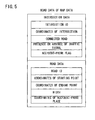
- Figure 5 shows one example of the road data.
- the road data includes intersection data indicating information in relation to an intersection and road data indicating information in relation to the road (connection) between the intersections.
- intersection data includes information of a plurality of intersections, and information of each intersection is stored by being brought into correspondence with identifying information (intersection ID) of the intersection.
- intersection data includes coordinates of an intersection, a connected road, the presence or absence of a traffic signal, an accident-prone flag, etc.
- the coordinates of an intersection include a latitude, a longitude and an altitude of the intersection.
- a road ID of the road connected to the relevant intersection is registered.
- the computer 12 can specify a direction of the road connected to the intersection on the basis of the information of the connected road and sets the direction of the connected road as a visually checking direction if the intersection is a dangerous place.
- the intersection is judged as a dangerous place.
- the accident-prone flag is turned on as to the intersection in need of a dangerous drive preventive intention where accidents frequently occur in the past. Accordingly, if information indicating "ON" is registered as information of the accident-prone flag, the intersection is determined as a dangerous place.
- the road data includes information of a plurality of roads, and information of each road is stored by being brought into correspondence with identifying information (road ID) of the road.
- the road data includes coordinates of a starting point, coordinates of an ending point, a width, coordinates of an accident-prone place, etc.
- the coordinates of the starting point and the ending point are coordinates (latitude, longitude, altitude) of both ends of the road. From the coordinates of the starting point and the ending point, a direction of the road can be calculated. Furthermore, because the width is registered together with the coordinates of the starting point and the ending point, the computer 12 can specify on which road the motor vehicle drives, and can thus determine whether or not there is a dangerous place down the road. Moreover, the coordinates (latitude, longitude, altitude) of an accident-prone place is registered in a case that a place in need of a dangerous drive preventive intention, such as a place where accidents frequently occur in the past exists on the road. This accident-prone place is also determined as a dangerous place.
- the alarming device 22 is an output device for issuing an alarm (warning) when it is determined that the driver did not perform a necessary motion when approaching the dangerous place.
- a sound outputting device, a display, a vibration outputting device, etc. may be provided.
- the alarming device 22 is provided in a case that the system 10 is configured so as to perform judgment for a dangerous drive preventive intention in real time and output an alarm in accordance with the determination result.
- a warning sound, a warning voice, etc. are output from the speaker on the basis of sound data, sound data, etc. stored in the computer 12 in advance.
- the warning sound, the warning voice, etc. may be made different depending on the motion which was not performed by the driver. For example, in a case that a visually checking motion was not performed, a voice instructing the driver to perform a visual check in a direction in which a visual check is required (left, right, or both ways) may be output, or in a case that a braking stance is not taken, a voice instructing the driver to release a foot from the accelerator to take a braking stance may be output.
- a warning image is displayed on the basis of the image data previously stored in the computer 12.
- the warning image is also made different depending on the motion which was not performed by the driver similar to the above-described sound output case.
- a car navigation system mounted on the motor vehicle may be utilized.
- the vibration outputting device is contained in a seat or attached to the driver for the purpose of alarming the driver by the vibrations.
- the vibration outputting device includes a vibrating motor, etc. and outputs vibrations in response to an instruction from the computer 12.
- a vibrating pattern and intensity may be made different depending on the motion which was not performed by the driver.
- the alarming device 22 outputs an alarm when the driver did not perform a motion for a dangerous driving prevention even if the motor vehicle approaches a dangerous place, and therefore, it is possible to urge the drive to perform a necessary motion and heighten a dangerous drive preventive intention of the driver.
- the driving data recording device 24 is a storing device for recording various data acquired during driving. This may be a flash memory incorporated in the computer 12, an HDD internal or external to the computer 12, a storage medium connected to the computer 12 like a memory card, or the like.
- the computer 12 records position data detected by the position detecting device 18, angular velocity data detected by the angular velocity sensors 14 and 16, etc. in the driving data recording device 24.
- the position data, the angular velocity data, etc. are stored by being brought into correspondence with the acquired time.
- the position data and the angular velocity data may be stored by being associated with each other.
- data indicating judgment results of a visual check and a braking stance with respect to a dangerous place may be recorded in the driving data recording device 24.
- Inventors et al. carried out experiments by utilizing an actual motor vehicle at unsignalized intersections in order to survey how much detection of a right-and-left checking motion and a braking stance which is conventionally difficult to measure can be made by the angular velocity sensors 14 and 16.
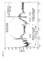
- Figure 6 and Figure 7 show angular velocity data when a driver who is judged as a safe driver and a driver who is judged as an unsafe driver, by his or her passenger and a confirmation by the video image respectively drive a zone (both drivers drive the same zone) in which four successive unsignalized intersections exist.
- a horizontal axis shown in each of Figure 6 and Figure 7 is a time (hh:mm:ss, that is, hour: minute: second), a vertical axis is an angular velocity (deg/s), and solid lines indicate an output from the angular velocity sensor 16 attached to the right foot, and dashed lines indicate an output from the angular velocity sensor 14 attached to the head.
- the angular velocity data of the test subject who is regarded as a safe driver shown in Figure 6 shows that he or she is sure to move the right foot to the brake pedal 32 (he or she does not necessarily foot down the pedal 32) and to frequently perform visual checks during passing through the intersection.
- the result in Figure 6 is roughly coincident with an occurring time and the number of occurrences of the right-and-left checking motion/the braking stance by the video checking.
- the data of the test subject who is regarded as an unsafe driver in Figure 7 shows that he or she never moves the foot on the brake pedal 32 during passing through the intersection (never takes a braking stance) and never makes a preparation in case of emergency. If only a footing down force of the pedal is focused, it is unclear whether a braking stance is taken. However, by the angular velocity sensor 16, a movement of the right foot between the accelerator pedal 30 and the brake pedal 32 can be detected, and therefore, it is possible to determine whether or not a braking stance is taken.
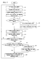
- Figure 8 shows one example of an operation of main processing of the computer 12 of the system 10.
- Figure 8 shows a flowchart when a judgment as to a dangerous drive preventive intention is performed in real time.
- step S1 position data indicating coordinates of a current position (latitude, longitude, altitude) is acquired from the position detecting device 18 and stored in the RAM.
- step S3 angular velocity data detected by the angular velocity sensor 14 attached to the head and angular velocity data detected by the angular velocity sensor 16 attached to the right toe are acquired and stored in the RAM.
- the position data and the angular velocity data which are acquired are recorded in the driving data recording device 24 in a step S5.
- the position data and angular velocity data are stored by being brought into correspondence with current time information acquired from a clock circuit integrated in the computer 12.
- a road along which the driver currently drives is specified.
- road ID road ID
- As shown in Figure 5 as road data, coordinates of the starting point and the ending point and a width are registered, and from them, an area of each road can be calculated. Accordingly, by determining in which area the coordinates of the current position is included, it is possible to specify the current road. In addition, from the change of the current position, a traveling direction of the motor vehicle can be calculated.
- a dangerous place (coordinates of an accident-prone place) exists by an end point (starting point or ending point) of the current road in the travel direction. Furthermore, if the end point (starting point or ending point) of the current road in the travel direction is an intersection, with reference to the intersection data, whether or not an unsignalized intersection is determined and whether or not the accident-prone flag is turned on is determined.
- the judgment of the presence or absence of the dangerous place in the step S7 may be executed for each change of the road.
- the judgment as to the presence or absence of the dangerous place may be executed on the road connected to the end point.
- a motion judging area of each dangerous place is set in a step S9.
- the visually checking motion and the braking stance need to be performed when the motor vehicle approaches the dangerous place, and therefore, when the motor vehicle approaches the dangerous place, whether or not a visually checking motion is performed and whether or not a braking stance is taken are judged.
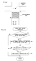
- the motion judging area is an area for judging whether or not the motor vehicle approaches the dangerous place, and an area where a visually checking motion and a braking stance are to be detected. Thus, the motion judging area is set ahead of the dangerous place.
- a predetermined range ahead of the dangerous place is set as a motion judging area.
- danger prevention or an averting motion such as a visual check and braking stance need to be executed.
- a predetermined range may be set with the line of the entrance of the intersection centered.
- 2 or 3 m to 7 or 8 m ahead of the entrance may be set.
- a predetermined range is set with reference to the dangerous place.
- an appropriate distance for which it is determined a visually checking motion and a braking stance (danger prevention or averting motion) may be started with respect to the dangerous place is selected.
- an appropriate distance for which it is determined that a visually checking motion and a braking stance (danger prevention or averting motion) should be ended with respect to a dangerous place is selected.
- a different area may be set in correspondence with a velocity of the motor vehicle. More specifically, if it is determined that the velocity of the motor vehicle is high (more than a predetermined value), the motion judging area may be set at a place further away from the dangerous place whereas if it is determined that the velocity of the motor vehicle is low (equal to or less than a predetermined value), the motion judging area may be set at a place closer to the dangerous place.
- the velocity of the motor vehicle is calculated from the change of the coordinates detected by the position detecting device 18 every predetermined time. Furthermore, in a case that the position detecting device 18 is provided with the speed sensor, the velocity detected by the sensor may be used.
- a visually checking direction of each dangerous place is set. For example, in a case that the dangerous place is an intersection, it is determined whether a road is connected to the left side or the right side of the intersection on the basis of the road data, and the direction that the road is connected is set as a visually checking direction. Accordingly, if the intersection is a crossroads as shown in Figure 9 , the right and left directions are set. Furthermore, if the dangerous place is set not to an intersection but to a road, the right and left directions may be set, for example, or the left direction, the right direction, or both directions may be set in correspondence with a terrain, a feature, etc. of the dangerous place.
- step S7 if "NO" in the step S7, that is, if a dangerous place does not exist ahead, the process proceeds to a step S13 as it is.
- step S13 processing of judging whether a visual check as one of the danger preventing or averting motion is performed is executed.
- a current position is within the motion judging area.
- the motion judging area is set in correspondence with a distance from the dangerous place (or entrance of the intersection) as described above, a distance between the coordinates of each dangerous place and the coordinates of the current position is calculated, and it is determined whether or not each calculated distance is a value between the upper limit and the lower limit of the distance defining each motion judging area.
- step S41 If "NO" in the step S41, the current position is not within the motion judging area, and therefore, the visual check judging processing is ended as it is, and the process returns to a step S15 in Figure 8 .
- the visually checking motion with respect to the dangerous place needs to be performed within the motion judging area, and therefore, if the current position is not within the motion judging area, the analysis of the angular velocity data of the head is not performed.
- step S41 the analysis of the angular velocity data of the head detected after the current position enters the motion judging area is performed in a step S43.
- the angular velocity to this direction is detected by the angular velocity sensor 14 attached to the head. Accordingly, by analyzing the angular velocity data after the current position enters the motion judging area, detection of a rotation to the set visually checking direction is tried.
- a rotation to the visually checking direction is detected, that is, it is determined whether or not a danger preventing motion or a danger averting motion is executed.
- the visually checking direction is the left direction
- it is determined whether or not a rotation to the left direction by more than a predetermined angle is detected.
- the visually checking direction is the right direction
- it is determined whether or not a rotation to the right direction by more than a predetermined angle is detected.
- the visually checking direction is both directions, it is determined whether or not a rotation to the left direction by more than a predetermined angle and a rotation to the right direction by more than a predetermined angle are detected.
- the head is rotated from a state that it is rotated to a first direction by more than a predetermined angle to a reverse direction, and thus, as a rotation to the reverse direction thereafter, a rotation from the first rotated state to the front and a rotation from the front to the reverse direction by more than a predetermined angle need to be detected.
- step S45 it is determined that a necessary visually checking motion (danger averting motion or danger preventing motion) is performed, and therefore, in a step S47, a visual check flag stored in a predetermined area of the RAM is turned on.
- step S45 a necessary visually checking motion (danger averting motion or danger preventing motion) is not detected, and the visual check judging processing is ended, and the process returns to the step S15 in Figure 8 .
- braking stance judging processing being the other one of the danger averting motion or the danger preventing motion is executed.
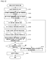
- One example of an operation of the braking stance judging processing is shown in Figure 11 .
- a motion of the braking stance corresponds to a situation that the right foot is on the side of the brake pedal 32 so as to immediately foot down the brake pedal 32 in case of emergency. Accordingly, in this embodiment, it is determined whether the position of the right foot is always on the side of the brake pedal 32 or on the side of the accelerator pedal 30.
- a step S61 in Figure 11 the angular velocity data of the right foot during a predetermined time period immediately before is analyzed.
- the driver moves the right foot between the brake pedal 32 and the accelerator pedal 30
- an angular velocity to the left direction or the right direction is detected by the angular velocity sensor 16 attached to the right toe.
- the angular velocity data of the right foot during the predetermined time period immediately before is analyzed to try to detect a rotation in the right direction or the left direction.
- a rotation to the right direction is detected. For example, it is determined whether or not an angle of the rotation for which the sign is negative, and the absolute value is equal to or more than a predetermined value is detected. If “YES” is determined in the step S63, it is determined that the driver moves the light foot to the side of the accelerator pedal 30, and therefore, the accelerator is stored as a position of the right foot in a step S65. On the other hand, if "NO" in the step S63, the process proceeds to a step S67.
- step S67 it is determined whether or not a rotation to the left direction is detected. For example, it is determined whether or not an angle of the rotation for which the sign is positive, and the absolute value is equal to or more than a predetermined value is detected. If “YES” in the step S67, it is determined that the driver moves the right foot to the side of the brake pedal 32, and therefore, in a step S69, the brake is stored as a position of the right foot. On the other hand, if "NO" in the step S67, the process proceeds to a step S71 as it is.
- step S71 it is determined whether or not the current position is within the motion judging area. If "NO" in the step S71, the braking stance need not be judged, and therefore, the braking stance judging processing is ended as it is, and the process returns to the step S17 shown in Figure 8 .
- step S71 determines whether or not the motor vehicle approaches the dangerous place. That is, in a step S73, it is determined whether or not the position of the right foot is on the brake pedal, that is, whether or not the danger preventing motion or the danger averting motion is executed. If “YES” in the step S73, it is determined that a braking stance (danger preventing motion or danger averting motion) is taken, and therefore, in a step S75, a braking stance flag stored in a predetermined area of the RAM is turned on. On the other hand, if "NO" in the step S73, a braking stance is not detected, and therefore, the braking stance judging processing is ended as it is, and the process returns to a step S17 shown in Figure 8 .
- step S17 it is determined whether or not the current position is out of the motion judging area. For example, it is determined whether or not the distance between the dangerous place (or the entrance of the intersection) and the current position is smaller than the lower limit of the distance defining the motion judging area. That is, in the step S17, it is determined whether or not a timing has come to finally judge whether or not a necessary motion is performed with respect to the dangerous place. If "NO" in the step S17, the process returns to the step S1.
- step S17 it is determined whether or not the visual check flag is turned on, and the braking stance flag is turned on in a step S19. If “NO” in the step S19, that is, if it is determined that the motor vehicle is going to arrive at the dangerous place without a necessary danger averting or a necessary prevention motion, alarm processing is executed in a step S21. Thus, the alarming device 22 outputs a warning sound, displays a warning image, and outputs vibrations.
- step S23 data indicating the result of the visual check and the braking stance with respect to the dangerous place are recorded in the driving data recording device 24. For example, information indicating whether or not a visual check is performed, information indicating whether or not a braking stance is taken, and time information, etc. are stored by being brought into correspondence with the coordinates of the dangerous place (or identifying information). After completion of the processing in the step S23, the process returns to the step S1.
- a visually checking motion and a braking stance are detected to thereby judge whether the danger averting or preventing motion is performed, and therefore, it is possible to successively check the dangerous drive preventive intention of the driver, output an alarm in real time, and record a judgment result of the dangerous drive preventive intention.
- the dangerous drive preventive intention of the driver can be quantitatively measured, and thus, it is of use for a preselection of a subject who has to take a reeducation course.
- a countermeasure to a loss of the durability of the effect of the reeducation course is made possible, such as evaluating the durability of the effect of the reeducation course, and making the subject take the course as necessary.
- the system 10 has the alarming device 22 and the driving data recording device 24, but in another embodiment, the system 10 may has any one of the alarming device 22 and the driving data recording device 24.
- the system 10 becomes an alarming system for issuing an alarm in real time depending on whether a motion for a dangerous driving prevention is performed whereas in a case that only the driving data recording device 24 is contained, the system 10 becomes a recording system for recording whether or not a motion for the dangerous driving prevention is performed.
- a visually checking motion and a braking stance are judged in real time, but in another embodiment, the data recorded during driving is analyzed in the post-mortem processing to thereby judge the danger averting or preventing motion, for example, a visually checking motion and a braking stance.
- processing similar to Figure 8 of successively reading recording data and making judgment may be executed postmortem, but another analyzing processing shown in Figure 12 may be executed.
- the post-mortem analyzing processing may be executed by the computer 12 of the system 10 in Figure 1 .
- recording data (angular velocity data and position data) of the driving data recording device 24 is fetched and taken in another computer, and by this computer, the analyzing processing may be executed.
- the computer needs to store the map data (road data) of the map database 20, or the computer needs to be able to obtain the map data from the map database 20.
- the recording data includes angular velocity data of the head, angular velocity data of the right toe, and position data of the motor vehicle which are recorded during driving.
- the angular velocity data and the position data are detected at predetermined time intervals, and each data is time-series data.
- a transfer pathway can be specified, and thus, the dangerous places on the transfer pathway can be extracted.
- a first dangerous place on the pathway out of the extracted dangerous places is set as an object to be surveyed. It is determined whether or not a visually checking motion and a braking stance are performed on the set dangerous place, that is, whether or not a necessary danger averting motion or a necessary danger preventing motion is performed.
- a motion judging area of the dangerous place is set.
- the processing in the step S107 is the same as that in the step S9 in Figure 8 described above.
- a visually checking direction of the dangerous place is set.
- the processing in the step S109 is the same as that in the step S11 described above.
- a step S111 visual check judging processing is executed with respect to the dangerous place.
- the visual check judging processing is approximately the same as the visual check judging processing in Figure 10 , but this is not the real-time processing, and therefore, the judgment in the step S41 in Figure 10 is not required.
- the angular velocity data of the head detected within the motion judging area is analyzed.
- the angular velocity data is recorded by being associated with the position data by using the time information or without using it, and therefore, it is possible to extract only the angular velocity data detected within the motion judging area. If a rotation in a visually checking direction is detected by the analysis, it is considered that the visual check (danger averting or preventing motion) in this direction is performed, and the visual check flag is turned on.
- braking stance judging processing with respect to the dangerous place is executed. More specifically, the angular velocity data of the right foot detected within the motion judging area is analyzed. Then, in a case that a predetermined rotation to the left direction is detected, it is considered that the position of the right foot is moved to the side of the brake, that is, that a danger averting or preventing motion is performed, and the braking stance flag is turned on.
- a step S115 the judgment results of the visual check and the braking stance with respect to the dangerous place are recorded in the RAM. For example, information indicating whether or not a visual check with respect to the set direction is performed in correspondence with the coordinates (or identifying information) of the dangerous place is, and the information indicating whether or not a braking stance is taken are stored.
- a step S117 it is determined whether or not surveys on all the dangerous places have been performed, and if "NO", in a step S119, a next dangerous place is set to a subject to be surveyed. Then, the process returns to the step S107 to perform processing for judging a visually checking motion and a braking stance with respect to the dangerous places.
- the results are output in a step S121.
- data including the judgment results with respect to all the dangerous places are generated and output as files, or the judgment results may be displayed on the display.
- processing of evaluating the dangerous drive preventive intention by the driver is further executed to output the evaluation result.
- the processing in the step S121 is ended, the analyzing processing is ended.
- the angular velocity sensors 14 and 16 are attached to the head and the right toe of the driver to record the angular velocity data by which a visually checking motion and a braking stance are judged.
- the kind of necessary motions may be changeable. Specifically, attribute information of the dangerous place is stored in the map data, and depending on each dangerous place, only the visually checking motion may be judged, and only the braking stance may be judged. More specifically, at a railroad crossing, a stop sign, etc., for example, motor vehicles are suspended under the rule, and therefore, if the dangerous place is such places, only the visually checking motion may be judged without judging a braking stance.
- the driver may be only one of the angular velocity sensor 14 of the head or the angular velocity sensor 16 of the right toe to thereby judge only one of the visually checking motion and the braking stance.
- the braking stance flag may be turned on. That is, a fact that the driver puts the right foot on the side of the brake pedal out of the motion judging area may be a condition for judgment of the braking stance.
- these conditions for judgment may be used differently depending on the attribute of the dangerous place (the degree of danger), for example.
- a fact that the right foot is moved to the side of the brake pedal into the dangerous place is a condition for taking a braking stance whereas with respect to a less dangerous place, a fact that the right foot is moved to the side of the brake pedal even once may be a condition for performing a braking stance.
- Figure 13 is an illustrative view showing one example of a state that a video camera and a microphone used in the third embodiment of the present invention are installed inside the motor vehicle.
- video image shooting an out-vehicle situation and an in-vehicle situation at least before and after the dangerous place are stored.
- the video image to be stored may be only the out-vehicle video image or only the in-vehicle video image.
- the video image may be a motion image in this embodiment, but may be a still image intermittently shot or successive still images.
- video cameras 36a and 36b are installed at an appropriate place within the vehicle 34, for example, on a rear-view mirror 35 in order to shoot a video image.
- the video camera 36a is turned ahead of the vehicle 34, and thus shoots an out-vehicle video image 40 as shown in Figure 14 .
- the video camera 36b turns backward of the vehicle 34 (in-vehicle), and thus shoots an in-vehicle video image 42 as shown in Figure 15 .
- a driver in the in-vehicle video image 42 puts on the cap 26 as shown in Figure 2 .
- angle of views or viewing angles of the video cameras 36a and 36b may be arbitrarily set, but in this embodiment, a camera having an angle of view of in the order of 140 degrees is used as an out-vehicle shooting camera 36a, and a camera having an angle of view in the order of 170 degrees is used as an in-vehicle shooting camera 36b.
- these video cameras 36a and 36b may be an infrared camera or a camera which is used to be switchable between a function of a normal camera and a function of an infrared camera.
- a microphone 38 is provided in addition to the video cameras 36a and 36b.
- the microphone 38 is mainly for capturing a sound in the vehicle and recording it. It is difficult to hear the sound of the out-vehicle from other sounds, and therefore, in this embodiment, a microphone for out-vehicle is not provided, but if necessary, another microphone (not illustrated) may be provided for recording an out-vehicle sound.
- the installation location of the video cameras 36a and 36b and the microphone 38 may be any location if the locations are able to function for their intended purpose.
- the configuration of the third embodiment is shown in Figure 16 .
- the configuration shown in Figure 16 is the same as that shown in Figure 1 except for the following points.
- video images shot by the video cameras 36a and 36b are input to the computer 12 as video image data via a proper interface not shown. Furthermore, a sound captured by the microphone 38 is input to the computer 12 via a similar interface as sound data.
- the driving data recording device 24 is set with a storing area or a recording area for storing the above-described video image data and sound data although especially not shown.
- the computer 12 activates the video cameras 36a and 36b and the microphone 38 via an interface not shown. Accordingly, at a start of the dangerous drive preventive intention judging operation, the video cameras 36a, 36b and the microphone 38 are activated, so that the data of the out-vehicle video image 40 shown in Figure 14 , the data of the in-vehicle video image 42 shown in Figure 15 and the sound data are recorded or stored at a first predetermined area of the driving data recording device 24 from this point.
- steps S1 to S23 in Figure 17 are the same as the steps S1 to S23 in Figure 8 including the subroutines ( Figure 10 and Figure 11 ) shown in the steps S13 and S15 except for that a step S22 is added, and therefore, the duplicated explanation is omitted.
- a visually checking motion that is, whether or not a danger averting or preventing motion is performed in the step S13, and whether or not a braking stance is taken, that is, whether or not dangerous driving averting or preventing motion is performed in the step S15. If a visually checking motion is performed, the visual check flag is turned on, and if not, the visual check flag is turned off. If a braking stance is performed, the braking stance flag is turned on, and if not, the braking stance flag is turned off.
- step S19 in Figure 17 it is determined whether or not the visual check flag is turned on, and whether or not the braking stance flag is turned on. If "NO" in the step S19, that is, if it is determined that the motor vehicle is going to arrive at the dangerous place without a necessary danger averting or prevention motion, alarm processing is executed in the step S21. Thus, the alarming device 22 outputs a warning sound, displays a warning image, and outputs vibrations.
- the computer 12 stores the data of the out-vehicle video image and the data of the in-vehicle video image of the video cameras 36a and 36b.
- the step S22 comprises a video image data storage (first video image data saver and second video image data saver) and sound data storage (first sound data saver and second sound data saver).
- the computer 12 records or stores the data of the out-vehicle video image 40 shown in Figure 14 and the data of the in-vehicle video image 42 shown in Figure 15 from the video cameras 36a and 36b, and the sound data from the microphone 38 which are activated in the step S0 in a first predetermined area of the driving data recording device 24. Then, if it is found that a dangerous place exists ahead in the step S7, the motion judging area is set in the step S9.
- the data of the out-vehicle video image and the in-vehicle video image from the video cameras 36a and 36b and the sound data from the microphone 38 from when the vehicle passes through the motion judging area set in the step S9 to when "NO" is determined in the step S19 are recorded in a second predetermined area of the driving data recording device 24.
- the data of the out-vehicle video image, the data of the in-vehicle video image and the sound data which are recorded in the second predetermined area are not cleared, and thus stored in the second predetermined area of the data recording device 24 so long as they are erased in a predetermined method.
- the video images shot by the video cameras and the sound captured by the microphone until the motor vehicle passes through the motion judging area are stored as data. Accordingly, by reproducing the video image data and sound data and making the driver see and hear the video image data and the sound data thereafter, it is possible to clearly show that the danger averting or preventing motion was not performed.
- the video image data and the sound data stored in the step S22 are not restricted to data during which the motor vehicle passes through the motion judging area, and may be data defined by the time decided three minutes before and one minute after the processing in the step S22 is executed, for example.
- the video image data and the sound data may be stored in another format in the step S22.
- the video image data and the sound data which are acquired in the step S0 are successively recorded.
- position data of the vehicle acquired from the position detecting device 18 is recorded, and time data acquired from a clock circuit not shown is recorded as a time stamp.
- the time stamp is recorded at arbitrary time intervals, for example, 30 seconds.
- Such a time stamp 44 is shown in Figure 18 .
- time data of "20081212100000” is shown, and this means February 12, 2008, 10: 00' 00", for example.
- time data after a lapse of 30 seconds, "20081212100030” is recorded.
- time data of "20081212100730" is recorded.
- the aforementioned another format is adding the identifying symbol 46 shown by the shade shown in Figure 18 to the time data of the time stamp.
- the identifying symbol 46 is added to the time data "20081212100300" to "20081212100700".
- the out-vehicle video image and the in-vehicle video image are stored, but the video image data to be stored may be data of at least one of the out-vehicle video image and the in-vehicle video image.
- the sound data is stored together with the video image data, but the sound data need not be stored.
- the microphone 38 can be omitted naturally.
- step S21 and the step S23 shown in Figure 17 may be omitted. This is because it is possible to instill the driver with a danger preventing intention by merely storing the video image data when the danger preventing or averting motion was not performed.
- the processing in the step S22 is executed.
- the processing in the steps S21 and S22 may be executed.
- the processing in the step S21 is executed only when the two flags are turned off, and the processing in the step S22 may be executed even if only one of the two flags is turned off.
- the third embodiment described above is an embodiment in which when in the first embodiment, it is judged that the driver fails to perform a danger preventing motion or a danger averting motion, data of the in-vehicle and the out-vehicle video images shot by the video camera 36 and data of the in-vehicle and out-vehicle sounds captured by the microphone 38 are stored, and they are used for safe-driving education for not only the driver but also other drivers.
- the recording data includes data of the in-vehicle and out-vehicle video images shot by the video camera 36 and data of the in-vehicle and out-vehicle sounds captured by the microphone 38 shown in Figure 16 are included. That is, in the fourth embodiment, by utilizing the configuration in Figure 16 , the recording data is acquired. Accordingly, in this embodiment, the recording data recorded in the first predetermined area of the driving data recording device 24 includes the video image data and the sound data as well as angular velocity data and position data.
- step S111 visual check judging processing of judging whether or not a visual check as one of the danger averting or preventing motion is performed is executed in a step S111
- braking stance judging processing of judging whether or not a braking stance as one of the danger averting or preventing motion is taken is executed in a step S113.
- the results are recorded in the step S115, but similar to the step S22 ( Figure 17 ) in the third embodiment, when as a result of the processing in each of the steps S111 and S113, at least any one of the visual check flag and the braking stance flag is not turned on, data of the in-vehicle and the out-vehicle video images shot by the video cameras 36a and 36b and sound data captured by the microphone 38 from when the vehicle passes through the motion judging area set in the step S107 ( Figure 12 ) to when the determination results in the respective steps S111 and S113 are obtained may be stored in the second predetermined area of the driving data recording device 24, or the identifying symbol as shown in Figure 18 may be stored.
- the angular velocity sensors 14 and 16 are utilized, but in another embodiment, another detecting device may be used.
- another detecting device may be used.
- the acceleration sensor In correspondence with a visually checking motion and a braking stance of the driver, an acceleration is changed, and therefore, by analyzing the acceleration data of the head and the acceleration data of the right toe as movement data, it is possible to judge whether or not a visually checking motion and a braking stance are performed.
- the visually checking motion follows a movement in the right and left direction of the head, and therefore, the acceleration sensor of the head is attached so as to detect an acceleration in at least the right and the left direction of the head.
- the acceleration sensor of the head is attached so as to detect an acceleration in at least the right and the left direction of the head. In a case that a movement to the right or the left direction is detected on the basis of the acceleration data of the head, it is possible to judge that a visually checking motion in the left or the right direction is performed.
- the braking stance can be judged by detecting a movement in the right and left direction of the right toe, and therefore, the acceleration sensor of the right toe is attached so as to detect an acceleration in at least the right and left direction of the right toe.
- the acceleration sensor of the right toe is attached so as to detect an acceleration in at least the right and left direction of the right toe.
- the acceleration sensor is generally subjected to a gravitational acceleration, and thus, the output is an addition of a gravitational acceleration component corresponding to the inclination of the sensor and an actual acceleration component.
- the influence of the gravitational acceleration component is less if any at all, but if a movement of the foot from one pedal to another has to be measured, the effect thereof is considerable.
- Figure 19 shows acceleration data when a movement of the right foot is measured by use of an acceleration sensor in place of the angular velocity sensor 16.
- the horizontal axis is a time
- the vertical axis is an acceleration (mG)
- X-axis direction an acceleration in a lateral direction
Landscapes
- Health & Medical Sciences (AREA)
- Life Sciences & Earth Sciences (AREA)
- Physics & Mathematics (AREA)
- Engineering & Computer Science (AREA)
- Public Health (AREA)
- Medical Informatics (AREA)
- Veterinary Medicine (AREA)
- General Physics & Mathematics (AREA)
- General Health & Medical Sciences (AREA)
- Animal Behavior & Ethology (AREA)
- Surgery (AREA)
- Molecular Biology (AREA)
- Biophysics (AREA)
- Pathology (AREA)
- Biomedical Technology (AREA)
- Heart & Thoracic Surgery (AREA)
- Child & Adolescent Psychology (AREA)
- Business, Economics & Management (AREA)
- Social Psychology (AREA)
- Psychology (AREA)
- Psychiatry (AREA)
- Hospice & Palliative Care (AREA)
- Educational Technology (AREA)
- Developmental Disabilities (AREA)
- Emergency Management (AREA)
- Physiology (AREA)
- Dentistry (AREA)
- Oral & Maxillofacial Surgery (AREA)
- Traffic Control Systems (AREA)
- Emergency Alarm Devices (AREA)
- Time Recorders, Dirve Recorders, Access Control (AREA)
Claims (12)
- System zum Beurteilen der Absicht eines präventiven gefährlichen Fahrmanövers zum Beurteilen der Absicht eines Fahrers eines Kraftfahrzeugs, ein präventives gefährliches Fahrmanövers an einer gefährliche Stelle durchzuführen, das Folgendes umfasst:einen Speicher zum Speichern von Winkelgeschwindigkeitsdaten, die von einem am Kopf des genannten Fahrers angebrachten Kopf-Winkelgeschwindigkeitssensor (14) erkannt und aufgezeichnet werden, von Winkelgeschwindigkeitsdaten, die von einem am rechten Zeh des genannten Fahrers angebrachten ZehWinkelgeschwindigkeitssensor (16) erkannt und aufgezeichnet werden, und von von einem Positionserkennungsgerät (18) erkannten und aufgezeichneten Positionsdaten des genannten Kraftfahrzeugs;eine erste Beurteilungsfunktion zum Beurteilen, auf der Basis der von dem genannten Kopf-Winkelgeschwindigkeitssensor erkannten Winkelgeschwindigkeitsdaten und der Positionsdaten des genannten Kraftfahrzeugs, ob eine Sichtprüfbewegung von dem genannten Fahrer durchgeführt wird oder nicht, wenn sich eine Position des genannten Kraftfahrzeugs der genannten gefährlichen Stelle nähert; undeine zweite Beurteilungsfunktion zum Beurteilen, auf der Basis der von dem genannten Zeh-Winkelgeschwindigkeitssensor erkannten Winkelgeschwindigkeitsdaten und der Positionsdaten des genannten Kraftfahrzeugs, ob eine Bremshaltung eingenommen wird oder nicht, wenn sich eine Position des genannten Kraftfahrzeugs der genannten gefährlichen Stelle nähert, undeine Ergebnisausgabefunktion zum Ausgeben von Beurteilungsergebnissen durch die genannte erste Beurteilungsfunktion und die genannte zweite Beurteilungsfunktion.
- System zum Beurteilen einer Absicht eines präventiven gefährlichen Fahrmanövers nach Anspruch 1, das ferner eine erste Alarmierfunktion zum Ausgeben eines Alarms umfasst, wenn die genannte erste Beurteilungsfunktion urteilt, dass die genannte Sichtprüfbewegung nicht durchgeführt wurde.
- System zum Beurteilen einer Absicht eines präventiven gefährlichen Fahrmanövers nach Anspruch 2, das ferner eine erste Videobilddaten-Speicherfunktion zum Speichern von Videobilddaten eines fahrzeuginternen Videobildes und/oder eines fahrzeugexternen Videobildes des genannten Kraftfahrzeugs umfasst, wenn die genannte erste Beurteilungsfunktion urteilt, dass die Sichtprüfbewegung nicht durchgeführt wurde.
- System zum Beurteilen der Absicht eines präventiven gefährlichen Fahrmanövers nach Anspruch 2 oder 3, das ferner eine erste Tondatenspeicherfunktion zum Speichern von Tondaten von wenigstens einem fahrzeuginternen Ton des genannten Kraftfahrzeugs umfasst, wenn die genannte erste Beurteilungsfunktion urteilt, dass die Sichtprüfbewegung nicht durchgeführt wurde.
- System zum Beurteilen der Absicht eines präventiven gefährlichen Fahrmanövers nach Anspruch 1, das ferner eine zweite Alarmierfunktion zum Ausgeben eines Alarms umfasst, wenn die genannte zweite Beurteilungsfunktion urteilt, dass keine Bremshaltung eingenommen wurde.
- System zum Beurteilen der Absicht eines präventiven gefährlichen Fahrmanövers nach Anspruch 5, das ferner eine zweite Videobilddaten-Speicherfunktion zum Speichern von Videobilddaten eines fahrzeuginternen Videobildes und/oder eines fahrzeugexternen Videobildes des genannten Kraftfahrzeugs umfasst, wenn die genannte zweite Beurteilungsfunktion urteilt, dass die Bremshaltung nicht eingenommen wurde.
- System zum Beurteilen der Absicht eines präventiven gefährlichen Fahrmanövers nach Anspruch 6, das ferner eine zweite Tondatenspeicherfunktion zum Speichern von Tondaten von wenigstens einem fahrzeuginternen Ton des genannten Kraftfahrzeugs umfasst, wenn die genannte zweite Beurteilungsfunktion urteilt, dass die Bremshaltung nicht eingenommen wurde.
- System zum Beurteilen der Absicht eines präventiven gefährlichen Fahrmanövers nach Anspruch 1, das einen ersten Rekorder zum Aufzeichnen eines Beurteilungsergebnisses durch die genannte erste Beurteilungsfunktion umfasst.
- System zum Beurteilen der Absicht eines präventiven gefährlichen Fahrmanövers nach Anspruch 1, das ferner einen zweiten Rekorder umfasst, der ferner zum Aufzeichnen eines Beurteilungsergebnisses durch die genannte zweite Beurteilungsfunktion ausgelegt ist.
- Verfahren zum Beurteilen der Absicht eines präventiven gefährlichen Fahrmanövers zum Beurteilen der Absicht eines Fahrers eines Kraftfahrzeugs, ein gefährliches präventives Fahrmanövers an einer gefährlichen Stelle durchzuführen, das die folgenden Schritte beinhaltet:(a) Aufzeichnen von Winkelgeschwindigkeitsdaten, die von einem am Kopf des genannten Fahrers angebrachten Kopf-Winkelgeschwindigkeitssensor (14) erkannt werden;(b) Aufzeichnen von Winkelgeschwindigkeitsdaten, die von einem am rechten Zeh des genannten Fahrers angebrachten Zeh-Winkelgeschwindigkeitssensor (16) erkannt werden;(c) Aufzeichnen von Positionsdaten des genannten Kraftfahrzeugs, wobie die genannten Positionsdaten von einer Positionserkennungsvorrichtung (18) erkannt werden; und(d) Beurteilen, ob eine Sichtprüfbewegung von dem genannten Fahrer durchgeführt wird oder nicht, wenn sich das genannte Kraftfahrzeug der genannten gefährlichen Stelle nähert, durch Analysieren der vom Kopf-Winkelgeschwindigkeitssensor erkannten Winkelgeschwindigkeitsdaten, der vom Zeh-Winkelgeschwindigkeitssensor erkannten Winkelgeschwindigkeitsdaten und der Positionsdaten.
- System zum Beurteilen der Absicht eines präventiven gefährlichen Fahrmanövers nach Anspruch 1, das ferner Folgendes umfasst:eine Kartendatenbank (20), in der gefährliche Stellen registriert sind;eine Ermittlungsfunktion zum Ermitteln, ob sich voraus eine gefährliche Stelle befindet oder nicht, auf der Basis der genannten Kartendatenbank und der genannten Positionsdaten;eine Bewegungsbeurteilungsbereich-Einstellfunktion zum Einstellen eines Bewegungsbeurteilungsbereichs, wenn die genannte Ermittlungsfunktion feststellt, dass sich voraus eine gefährliche Stelle befindet, wobeidie genannte erste Beurteilungsfunktion so ausgelegt ist, dass sie beurteilt, ob eine Sichtprüfbewegung durch den genannten Fahrer durchgeführt wird oder nicht, wenn sich das genannte Kraftfahrzeug innerhalb des genannten Bewegungsbeurteilungsbereichs befindet, und wobei die genannte zweite Beurteilungsfunktion so ausgelegt ist, dass sie beurteilt, ob eine Bremshaltung eingenommen wird oder nicht, wenn sich das genannte Kraftfahrzeug innerhalb des genannten Bewegungsbeurteilungsbereichs befindet.
- System zum Beurteilen der Absicht eines präventiven gefährlichen Fahrmanövers nach Anspruch 1, das ferner Folgendes umfasst:eine Richtungseinstellfunktion zum Einstellen einer Sichtprüfrichtung, in der eine Sichtprüfung von dem genannten Fahrer durchgeführt werden soll, wobeidie genannte erste Beurteilungsfunktion so ausgelegt ist, dass sie beurteilt, ob eine Drehung des Kopfes des genannten Fahrers in der genannten Sichtprüfrichtung des genannten Kopfes erkannt wird oder nicht.
Applications Claiming Priority (3)
| Application Number | Priority Date | Filing Date | Title |
|---|---|---|---|
| JP2008011239 | 2008-01-22 | ||
| JP2008318057A JP5499277B2 (ja) | 2008-01-22 | 2008-12-15 | 危険運転予防意識判定システムおよび危険運転予防意識判定方法 |
| PCT/JP2009/051146 WO2009093726A1 (ja) | 2008-01-22 | 2009-01-20 | 危険運転予防意識判定システムおよび危険運転予防意識判定方法 |
Publications (3)
| Publication Number | Publication Date |
|---|---|
| EP2246831A1 EP2246831A1 (de) | 2010-11-03 |
| EP2246831A4 EP2246831A4 (de) | 2014-12-03 |
| EP2246831B1 true EP2246831B1 (de) | 2016-01-06 |
Family
ID=40901225
Family Applications (1)
| Application Number | Title | Priority Date | Filing Date |
|---|---|---|---|
| EP09703655.2A Active EP2246831B1 (de) | 2008-01-22 | 2009-01-20 | System und verfahren zur beurteilung gefährlicher präventiver fahrmanöverabsichten |
Country Status (5)
| Country | Link |
|---|---|
| EP (1) | EP2246831B1 (de) |
| JP (1) | JP5499277B2 (de) |
| KR (1) | KR20100114044A (de) |
| CN (1) | CN101952868A (de) |
| WO (1) | WO2009093726A1 (de) |
Families Citing this family (20)
| Publication number | Priority date | Publication date | Assignee | Title |
|---|---|---|---|---|
| JP5212312B2 (ja) * | 2009-08-20 | 2013-06-19 | 株式会社デンソー | 安全運転診断装置 |
| JP2011118601A (ja) * | 2009-12-02 | 2011-06-16 | Advanced Telecommunication Research Institute International | 交通ハザードマップ生成装置 |
| EP2827317B1 (de) * | 2012-03-16 | 2020-01-08 | Nissan Motor Co., Ltd | Vorrichtung zur bestimmung der empfindlichkeit gegenüber der vorhersage unerwarteter situationen |
| EP2830031A4 (de) * | 2012-03-19 | 2016-08-10 | Toyota Motor Co Ltd | Vorrichtung zur unterstützung einer kollisionsvermeidung |
| JP5770215B2 (ja) * | 2013-04-08 | 2015-08-26 | 中国電力株式会社 | 作業エリアに存在する危険箇所に関する情報を収集する方法、及び危険箇所情報収集システム |
| EP3316231B1 (de) | 2014-01-06 | 2021-11-10 | iOnRoad Technologies, Limited | Alarmauslösungskorrelation zwischen kopfmontierten bilddaten und externer vorrichtung |
| WO2016073620A1 (en) * | 2014-11-06 | 2016-05-12 | Maven Machines, Inc. | System for monitoring vehicle operator compliance with safe operating conditions |
| KR101612824B1 (ko) | 2014-11-20 | 2016-04-15 | 현대자동차주식회사 | Hmd를 이용한 운전자 상태 모니터링 방법 및 장치 |
| US10024684B2 (en) * | 2014-12-02 | 2018-07-17 | Operr Technologies, Inc. | Method and system for avoidance of accidents |
| US9905131B2 (en) * | 2015-12-29 | 2018-02-27 | Thunder Power New Energy Vehicle Development Company Limited | Onboard vehicle notification system |
| JP6619306B2 (ja) * | 2016-08-24 | 2019-12-11 | トヨタ自動車株式会社 | 運転者行動評価装置及び運転者行動評価方法 |
| JP6992493B2 (ja) * | 2017-12-25 | 2022-01-13 | いすゞ自動車株式会社 | 運転状態判定装置及び運転状態判定方法 |
| JP7127282B2 (ja) * | 2017-12-25 | 2022-08-30 | いすゞ自動車株式会社 | 運転状態判定装置及び運転状態判定方法 |
| KR101979863B1 (ko) * | 2017-12-29 | 2019-08-28 | 경일대학교산학협력단 | IoT 기반 스마트 장치를 이용한 안전 운전 서비스를 제공하기 위한 시스템, 이를 위한 방법 및 이 방법을 수행하는 프로그램이 기록된 컴퓨터 판독 가능한 기록매체 |
| JP7163152B2 (ja) * | 2018-11-28 | 2022-10-31 | 京セラ株式会社 | 画像処理装置、撮像装置、移動体及び画像処理方法 |
| CN111002989A (zh) * | 2019-11-06 | 2020-04-14 | 上海擎感智能科技有限公司 | 驾驶安全监测方法、车载终端及计算机可读存储介质 |
| CN110979180B (zh) * | 2019-12-25 | 2021-06-15 | 三一汽车制造有限公司 | 防止危险驾驶的控制方法、装置和车辆 |
| CN111968365B (zh) * | 2020-07-24 | 2022-02-15 | 武汉理工大学 | 一种非信号交叉口车辆行为分析方法、系统及存储介质 |
| JP7533115B2 (ja) * | 2020-10-21 | 2024-08-14 | オムロン株式会社 | 運転評価装置およびこれを備えた運転評価システム、運転評価方法、運転評価プログラム |
| CN113112772A (zh) * | 2021-03-23 | 2021-07-13 | 黄启敏 | 一种能减少交通事故的汽车驾驶鞋及控制方法 |
Family Cites Families (14)
| Publication number | Priority date | Publication date | Assignee | Title |
|---|---|---|---|---|
| JP3214122B2 (ja) * | 1993-01-19 | 2001-10-02 | 三菱電機株式会社 | 危険状況警報装置 |
| JP2000111568A (ja) * | 1998-09-30 | 2000-04-21 | Mazda Motor Corp | 運動状態検出センサ |
| JP2002042288A (ja) * | 2000-07-26 | 2002-02-08 | Yazaki Corp | 運行状態記録装置及びそれを利用した運行管理システム |
| JP4729784B2 (ja) * | 2000-11-01 | 2011-07-20 | アイシン精機株式会社 | 警報装置 |
| JP2002331850A (ja) | 2001-05-07 | 2002-11-19 | Nissan Motor Co Ltd | 運転行動意図検出装置 |
| JP3760894B2 (ja) * | 2002-07-02 | 2006-03-29 | 有限会社エムアンドエル | 車両運転管理装置、システムおよび方法 |
| EP1695310B1 (de) * | 2003-11-30 | 2008-09-03 | Volvo Technology Corporation | Verfahren und system zum erkennen einer fahrerbeeinträchtigung |
| JP2005209073A (ja) * | 2004-01-26 | 2005-08-04 | National Institute Of Advanced Industrial & Technology | 運転支援システム |
| JP2005293032A (ja) * | 2004-03-31 | 2005-10-20 | Mitsubishi Electric Information Systems Corp | 車輌運転状況監視システム及びこのシステム用の車輌運転状況監視プログラム。 |
| CN1676286A (zh) * | 2004-04-02 | 2005-10-05 | 李朝辉 | 生物信息随动即时示教控制机器人 |
| JP2006227905A (ja) * | 2005-02-17 | 2006-08-31 | Toyota Motor Corp | 車両用情報報知装置 |
| JP4815943B2 (ja) * | 2005-08-19 | 2011-11-16 | 株式会社デンソー | 危険箇所情報表示装置 |
| WO2007049596A1 (ja) * | 2005-10-28 | 2007-05-03 | Pioneer Corporation | 情報記録装置、情報記録方法、情報記録プログラムおよびコンピュータに読み取り可能な記録媒体 |
| JP4780711B2 (ja) * | 2006-06-13 | 2011-09-28 | 株式会社国際電気通信基礎技術研究所 | 運転動作解析装置および運転動作解析方法 |
-
2008
- 2008-12-15 JP JP2008318057A patent/JP5499277B2/ja active Active
-
2009
- 2009-01-20 CN CN2009801028124A patent/CN101952868A/zh active Pending
- 2009-01-20 KR KR1020107016374A patent/KR20100114044A/ko not_active Withdrawn
- 2009-01-20 WO PCT/JP2009/051146 patent/WO2009093726A1/ja not_active Ceased
- 2009-01-20 EP EP09703655.2A patent/EP2246831B1/de active Active
Also Published As
| Publication number | Publication date |
|---|---|
| KR20100114044A (ko) | 2010-10-22 |
| JP2009199583A (ja) | 2009-09-03 |
| CN101952868A (zh) | 2011-01-19 |
| EP2246831A1 (de) | 2010-11-03 |
| WO2009093726A1 (ja) | 2009-07-30 |
| JP5499277B2 (ja) | 2014-05-21 |
| EP2246831A4 (de) | 2014-12-03 |
Similar Documents
| Publication | Publication Date | Title |
|---|---|---|
| EP2246831A1 (de) | System und verfahren zur beurteilung gefährlicher präventiver fahrmanöverabsichten | |
| JP5408572B2 (ja) | 運転行動自動評価システム | |
| JP7355151B2 (ja) | 情報処理装置、情報処理方法、プログラム | |
| US11801843B2 (en) | Method, system, and computer program product for determining safety-critical traffic scenarios for driver assistance systems (DAS) and highly automated driving functions (HAD) | |
| JP6342858B2 (ja) | 運転評価装置 | |
| JP6218618B2 (ja) | 運転支援装置、運転支援方法及び運転支援プログラム | |
| US20120206252A1 (en) | Lane departure warning system | |
| JP2011118601A (ja) | 交通ハザードマップ生成装置 | |
| US20220189221A1 (en) | Information recording device, information recording method, and program for recording information | |
| JP2012155516A (ja) | 車両挙動記録システム | |
| JP5220444B2 (ja) | 運転アドバイス装置 | |
| CN119809881A (zh) | 用于驾驶技能培训的学员安全操作监测装置 | |
| JP2009230246A (ja) | 運転状態警告システム、運転状態警告方法及びプログラム | |
| CN110383361A (zh) | 用于在光信号设备处提醒驾驶员起动的方法和装置 | |
| JP2006209455A (ja) | 車両用運転診断装置、車両用運転診断システム、及び車両用運転診断方法 | |
| JP2006209455A5 (de) | ||
| Vavouranakis et al. | Recognizing driving behaviour using smartphones | |
| JP5691065B2 (ja) | 危険運転予防意識判定システムおよび危険運転予防意識判定方法 | |
| JP7482899B2 (ja) | ドライバの携帯電話の注意散漫の決定、スコアリング、およびレポート | |
| JP7267760B2 (ja) | 運転評価システム及び車載器 | |
| JP7364365B2 (ja) | 車載器及び運転評価システム | |
| JP2020123213A (ja) | 運転評価システム及び車載器 | |
| JP4866061B2 (ja) | 情報記録装置、情報記録方法、情報記録プログラムおよびコンピュータに読み取り可能な記録媒体 | |
| JP2018190232A (ja) | 車載器 | |
| JP7606796B1 (ja) | 交通安全支援装置、携帯情報端末、及びプログラム |
Legal Events
| Date | Code | Title | Description |
|---|---|---|---|
| PUAI | Public reference made under article 153(3) epc to a published international application that has entered the european phase |
Free format text: ORIGINAL CODE: 0009012 |
|
| 17P | Request for examination filed |
Effective date: 20100721 |
|
| AK | Designated contracting states |
Kind code of ref document: A1 Designated state(s): AT BE BG CH CY CZ DE DK EE ES FI FR GB GR HR HU IE IS IT LI LT LU LV MC MK MT NL NO PL PT RO SE SI SK TR |
|
| AX | Request for extension of the european patent |
Extension state: AL BA RS |
|
| DAX | Request for extension of the european patent (deleted) | ||
| A4 | Supplementary search report drawn up and despatched |
Effective date: 20141030 |
|
| RIC1 | Information provided on ipc code assigned before grant |
Ipc: G08G 1/16 20060101AFI20141024BHEP |
|
| GRAP | Despatch of communication of intention to grant a patent |
Free format text: ORIGINAL CODE: EPIDOSNIGR1 |
|
| INTG | Intention to grant announced |
Effective date: 20150709 |
|
| GRAS | Grant fee paid |
Free format text: ORIGINAL CODE: EPIDOSNIGR3 |
|
| GRAA | (expected) grant |
Free format text: ORIGINAL CODE: 0009210 |
|
| AK | Designated contracting states |
Kind code of ref document: B1 Designated state(s): AT BE BG CH CY CZ DE DK EE ES FI FR GB GR HR HU IE IS IT LI LT LU LV MC MK MT NL NO PL PT RO SE SI SK TR |
|
| REG | Reference to a national code |
Ref country code: GB Ref legal event code: FG4D |
|
| REG | Reference to a national code |
Ref country code: CH Ref legal event code: EP |
|
| REG | Reference to a national code |
Ref country code: IE Ref legal event code: FG4D |
|
| REG | Reference to a national code |
Ref country code: AT Ref legal event code: REF Ref document number: 769437 Country of ref document: AT Kind code of ref document: T Effective date: 20160215 |
|
| REG | Reference to a national code |
Ref country code: DE Ref legal event code: R096 Ref document number: 602009035546 Country of ref document: DE |
|
| REG | Reference to a national code |
Ref country code: LT Ref legal event code: MG4D |
|
| REG | Reference to a national code |
Ref country code: NL Ref legal event code: MP Effective date: 20160106 |
|
| REG | Reference to a national code |
Ref country code: AT Ref legal event code: MK05 Ref document number: 769437 Country of ref document: AT Kind code of ref document: T Effective date: 20160106 |
|
| PG25 | Lapsed in a contracting state [announced via postgrant information from national office to epo] |
Ref country code: BE Free format text: LAPSE BECAUSE OF NON-PAYMENT OF DUE FEES Effective date: 20160131 |
|
| PG25 | Lapsed in a contracting state [announced via postgrant information from national office to epo] |
Ref country code: NL Free format text: LAPSE BECAUSE OF FAILURE TO SUBMIT A TRANSLATION OF THE DESCRIPTION OR TO PAY THE FEE WITHIN THE PRESCRIBED TIME-LIMIT Effective date: 20160106 |
|
| PG25 | Lapsed in a contracting state [announced via postgrant information from national office to epo] |
Ref country code: FI Free format text: LAPSE BECAUSE OF FAILURE TO SUBMIT A TRANSLATION OF THE DESCRIPTION OR TO PAY THE FEE WITHIN THE PRESCRIBED TIME-LIMIT Effective date: 20160106 Ref country code: NO Free format text: LAPSE BECAUSE OF FAILURE TO SUBMIT A TRANSLATION OF THE DESCRIPTION OR TO PAY THE FEE WITHIN THE PRESCRIBED TIME-LIMIT Effective date: 20160406 Ref country code: HR Free format text: LAPSE BECAUSE OF FAILURE TO SUBMIT A TRANSLATION OF THE DESCRIPTION OR TO PAY THE FEE WITHIN THE PRESCRIBED TIME-LIMIT Effective date: 20160106 Ref country code: GR Free format text: LAPSE BECAUSE OF FAILURE TO SUBMIT A TRANSLATION OF THE DESCRIPTION OR TO PAY THE FEE WITHIN THE PRESCRIBED TIME-LIMIT Effective date: 20160407 Ref country code: IT Free format text: LAPSE BECAUSE OF FAILURE TO SUBMIT A TRANSLATION OF THE DESCRIPTION OR TO PAY THE FEE WITHIN THE PRESCRIBED TIME-LIMIT Effective date: 20160106 Ref country code: ES Free format text: LAPSE BECAUSE OF FAILURE TO SUBMIT A TRANSLATION OF THE DESCRIPTION OR TO PAY THE FEE WITHIN THE PRESCRIBED TIME-LIMIT Effective date: 20160106 |
|
| PG25 | Lapsed in a contracting state [announced via postgrant information from national office to epo] |
Ref country code: LV Free format text: LAPSE BECAUSE OF FAILURE TO SUBMIT A TRANSLATION OF THE DESCRIPTION OR TO PAY THE FEE WITHIN THE PRESCRIBED TIME-LIMIT Effective date: 20160106 Ref country code: PL Free format text: LAPSE BECAUSE OF FAILURE TO SUBMIT A TRANSLATION OF THE DESCRIPTION OR TO PAY THE FEE WITHIN THE PRESCRIBED TIME-LIMIT Effective date: 20160106 Ref country code: LT Free format text: LAPSE BECAUSE OF FAILURE TO SUBMIT A TRANSLATION OF THE DESCRIPTION OR TO PAY THE FEE WITHIN THE PRESCRIBED TIME-LIMIT Effective date: 20160106 Ref country code: SE Free format text: LAPSE BECAUSE OF FAILURE TO SUBMIT A TRANSLATION OF THE DESCRIPTION OR TO PAY THE FEE WITHIN THE PRESCRIBED TIME-LIMIT Effective date: 20160106 Ref country code: AT Free format text: LAPSE BECAUSE OF FAILURE TO SUBMIT A TRANSLATION OF THE DESCRIPTION OR TO PAY THE FEE WITHIN THE PRESCRIBED TIME-LIMIT Effective date: 20160106 Ref country code: PT Free format text: LAPSE BECAUSE OF FAILURE TO SUBMIT A TRANSLATION OF THE DESCRIPTION OR TO PAY THE FEE WITHIN THE PRESCRIBED TIME-LIMIT Effective date: 20160506 Ref country code: IS Free format text: LAPSE BECAUSE OF FAILURE TO SUBMIT A TRANSLATION OF THE DESCRIPTION OR TO PAY THE FEE WITHIN THE PRESCRIBED TIME-LIMIT Effective date: 20160506 |
|
| REG | Reference to a national code |
Ref country code: CH Ref legal event code: PL |
|
| REG | Reference to a national code |
Ref country code: DE Ref legal event code: R097 Ref document number: 602009035546 Country of ref document: DE |
|
| PG25 | Lapsed in a contracting state [announced via postgrant information from national office to epo] |
Ref country code: LI Free format text: LAPSE BECAUSE OF NON-PAYMENT OF DUE FEES Effective date: 20160131 Ref country code: MC Free format text: LAPSE BECAUSE OF FAILURE TO SUBMIT A TRANSLATION OF THE DESCRIPTION OR TO PAY THE FEE WITHIN THE PRESCRIBED TIME-LIMIT Effective date: 20160106 Ref country code: EE Free format text: LAPSE BECAUSE OF FAILURE TO SUBMIT A TRANSLATION OF THE DESCRIPTION OR TO PAY THE FEE WITHIN THE PRESCRIBED TIME-LIMIT Effective date: 20160106 Ref country code: DK Free format text: LAPSE BECAUSE OF FAILURE TO SUBMIT A TRANSLATION OF THE DESCRIPTION OR TO PAY THE FEE WITHIN THE PRESCRIBED TIME-LIMIT Effective date: 20160106 Ref country code: CH Free format text: LAPSE BECAUSE OF NON-PAYMENT OF DUE FEES Effective date: 20160131 |
|
| REG | Reference to a national code |
Ref country code: IE Ref legal event code: MM4A |
|
| PLBE | No opposition filed within time limit |
Free format text: ORIGINAL CODE: 0009261 |
|
| STAA | Information on the status of an ep patent application or granted ep patent |
Free format text: STATUS: NO OPPOSITION FILED WITHIN TIME LIMIT |
|
| PG25 | Lapsed in a contracting state [announced via postgrant information from national office to epo] |
Ref country code: SK Free format text: LAPSE BECAUSE OF FAILURE TO SUBMIT A TRANSLATION OF THE DESCRIPTION OR TO PAY THE FEE WITHIN THE PRESCRIBED TIME-LIMIT Effective date: 20160106 Ref country code: RO Free format text: LAPSE BECAUSE OF FAILURE TO SUBMIT A TRANSLATION OF THE DESCRIPTION OR TO PAY THE FEE WITHIN THE PRESCRIBED TIME-LIMIT Effective date: 20160106 Ref country code: CZ Free format text: LAPSE BECAUSE OF FAILURE TO SUBMIT A TRANSLATION OF THE DESCRIPTION OR TO PAY THE FEE WITHIN THE PRESCRIBED TIME-LIMIT Effective date: 20160106 |
|
| 26N | No opposition filed |
Effective date: 20161007 |
|
| PG25 | Lapsed in a contracting state [announced via postgrant information from national office to epo] |
Ref country code: BE Free format text: LAPSE BECAUSE OF FAILURE TO SUBMIT A TRANSLATION OF THE DESCRIPTION OR TO PAY THE FEE WITHIN THE PRESCRIBED TIME-LIMIT Effective date: 20160106 |
|
| REG | Reference to a national code |
Ref country code: FR Ref legal event code: ST Effective date: 20161128 |
|
| PG25 | Lapsed in a contracting state [announced via postgrant information from national office to epo] |
Ref country code: IE Free format text: LAPSE BECAUSE OF NON-PAYMENT OF DUE FEES Effective date: 20160120 Ref country code: FR Free format text: LAPSE BECAUSE OF NON-PAYMENT OF DUE FEES Effective date: 20160307 |
|
| PG25 | Lapsed in a contracting state [announced via postgrant information from national office to epo] |
Ref country code: BG Free format text: LAPSE BECAUSE OF FAILURE TO SUBMIT A TRANSLATION OF THE DESCRIPTION OR TO PAY THE FEE WITHIN THE PRESCRIBED TIME-LIMIT Effective date: 20160406 Ref country code: SI Free format text: LAPSE BECAUSE OF FAILURE TO SUBMIT A TRANSLATION OF THE DESCRIPTION OR TO PAY THE FEE WITHIN THE PRESCRIBED TIME-LIMIT Effective date: 20160106 |
|
| PG25 | Lapsed in a contracting state [announced via postgrant information from national office to epo] |
Ref country code: MT Free format text: LAPSE BECAUSE OF FAILURE TO SUBMIT A TRANSLATION OF THE DESCRIPTION OR TO PAY THE FEE WITHIN THE PRESCRIBED TIME-LIMIT Effective date: 20160106 |
|
| PG25 | Lapsed in a contracting state [announced via postgrant information from national office to epo] |
Ref country code: CY Free format text: LAPSE BECAUSE OF FAILURE TO SUBMIT A TRANSLATION OF THE DESCRIPTION OR TO PAY THE FEE WITHIN THE PRESCRIBED TIME-LIMIT Effective date: 20160106 Ref country code: HU Free format text: LAPSE BECAUSE OF FAILURE TO SUBMIT A TRANSLATION OF THE DESCRIPTION OR TO PAY THE FEE WITHIN THE PRESCRIBED TIME-LIMIT; INVALID AB INITIO Effective date: 20090120 |
|
| PG25 | Lapsed in a contracting state [announced via postgrant information from national office to epo] |
Ref country code: LU Free format text: LAPSE BECAUSE OF NON-PAYMENT OF DUE FEES Effective date: 20160120 Ref country code: TR Free format text: LAPSE BECAUSE OF FAILURE TO SUBMIT A TRANSLATION OF THE DESCRIPTION OR TO PAY THE FEE WITHIN THE PRESCRIBED TIME-LIMIT Effective date: 20160106 Ref country code: MK Free format text: LAPSE BECAUSE OF FAILURE TO SUBMIT A TRANSLATION OF THE DESCRIPTION OR TO PAY THE FEE WITHIN THE PRESCRIBED TIME-LIMIT Effective date: 20160106 Ref country code: MT Free format text: LAPSE BECAUSE OF FAILURE TO SUBMIT A TRANSLATION OF THE DESCRIPTION OR TO PAY THE FEE WITHIN THE PRESCRIBED TIME-LIMIT Effective date: 20160131 |
|
| REG | Reference to a national code |
Ref country code: DE Ref legal event code: R082 Ref document number: 602009035546 Country of ref document: DE Representative=s name: VENNER SHIPLEY GERMANY LLP, DE Ref country code: DE Ref legal event code: R082 Ref document number: 602009035546 Country of ref document: DE Representative=s name: VENNER SHIPLEY LLP, DE |
|
| PGFP | Annual fee paid to national office [announced via postgrant information from national office to epo] |
Ref country code: GB Payment date: 20241128 Year of fee payment: 17 |
|
| PGFP | Annual fee paid to national office [announced via postgrant information from national office to epo] |
Ref country code: DE Payment date: 20241203 Year of fee payment: 17 |