EP2246935A1 - Structure d'antenne multi-boucles et appareil électronique portatif utilisant cette structure d'antenne - Google Patents
Structure d'antenne multi-boucles et appareil électronique portatif utilisant cette structure d'antenne Download PDFInfo
- Publication number
- EP2246935A1 EP2246935A1 EP10150776A EP10150776A EP2246935A1 EP 2246935 A1 EP2246935 A1 EP 2246935A1 EP 10150776 A EP10150776 A EP 10150776A EP 10150776 A EP10150776 A EP 10150776A EP 2246935 A1 EP2246935 A1 EP 2246935A1
- Authority
- EP
- European Patent Office
- Prior art keywords
- loop antenna
- radiating body
- frequency
- frequency radiating
- connecting part
- Prior art date
- Legal status (The legal status is an assumption and is not a legal conclusion. Google has not performed a legal analysis and makes no representation as to the accuracy of the status listed.)
- Withdrawn
Links
Images


Classifications
-
- H—ELECTRICITY
- H01—ELECTRIC ELEMENTS
- H01Q—ANTENNAS, i.e. RADIO AERIALS
- H01Q9/00—Electrically-short antennas having dimensions not more than twice the operating wavelength and consisting of conductive active radiating elements
- H01Q9/04—Resonant antennas
- H01Q9/30—Resonant antennas with feed to end of elongated active element, e.g. unipole
- H01Q9/42—Resonant antennas with feed to end of elongated active element, e.g. unipole with folded element, the folded parts being spaced apart a small fraction of the operating wavelength
-
- H—ELECTRICITY
- H01—ELECTRIC ELEMENTS
- H01Q—ANTENNAS, i.e. RADIO AERIALS
- H01Q1/00—Details of, or arrangements associated with, antennas
- H01Q1/12—Supports; Mounting means
- H01Q1/22—Supports; Mounting means by structural association with other equipment or articles
- H01Q1/24—Supports; Mounting means by structural association with other equipment or articles with receiving set
- H01Q1/241—Supports; Mounting means by structural association with other equipment or articles with receiving set used in mobile communications, e.g. GSM
- H01Q1/242—Supports; Mounting means by structural association with other equipment or articles with receiving set used in mobile communications, e.g. GSM specially adapted for hand-held use
- H01Q1/243—Supports; Mounting means by structural association with other equipment or articles with receiving set used in mobile communications, e.g. GSM specially adapted for hand-held use with built-in antennas
-
- H—ELECTRICITY
- H01—ELECTRIC ELEMENTS
- H01Q—ANTENNAS, i.e. RADIO AERIALS
- H01Q1/00—Details of, or arrangements associated with, antennas
- H01Q1/36—Structural form of radiating elements, e.g. cone, spiral, umbrella; Particular materials used therewith
- H01Q1/38—Structural form of radiating elements, e.g. cone, spiral, umbrella; Particular materials used therewith formed by a conductive layer on an insulating support
-
- H—ELECTRICITY
- H01—ELECTRIC ELEMENTS
- H01Q—ANTENNAS, i.e. RADIO AERIALS
- H01Q5/00—Arrangements for simultaneous operation of antennas on two or more different wavebands, e.g. dual-band or multi-band arrangements
-
- H—ELECTRICITY
- H01—ELECTRIC ELEMENTS
- H01Q—ANTENNAS, i.e. RADIO AERIALS
- H01Q5/00—Arrangements for simultaneous operation of antennas on two or more different wavebands, e.g. dual-band or multi-band arrangements
- H01Q5/30—Arrangements for providing operation on different wavebands
- H01Q5/307—Individual or coupled radiating elements, each element being fed in an unspecified way
- H01Q5/342—Individual or coupled radiating elements, each element being fed in an unspecified way for different propagation modes
- H01Q5/357—Individual or coupled radiating elements, each element being fed in an unspecified way for different propagation modes using a single feed point
- H01Q5/364—Creating multiple current paths
- H01Q5/371—Branching current paths
-
- H—ELECTRICITY
- H01—ELECTRIC ELEMENTS
- H01Q—ANTENNAS, i.e. RADIO AERIALS
- H01Q7/00—Loop antennas with a substantially uniform current distribution around the loop and having a directional radiation pattern in a plane perpendicular to the plane of the loop
Definitions
- the subject application relates in general to an antenna and a hand-held electronic device using the same, and more particularly to a multi-loop antenna structure and a hand-held electronic device using the same.
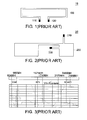
- the generally known loop antenna 10 includes a feeding point 110, a grounding point 120 and a symmetric radiating body 130. There is a complete loop between the feeding point 110, the grounding point 120 and radiating body 130. That is, the current flowing into the feeding point 110 equals the current flowing out of the grounding point 120, therefore the generally known loop antenna 10 is also called balance antenna. As the generally known loop antenna 10 is big in size and the design of the mobile phone is directed towards slimness, lightweight and compactness, the generally known loop antenna 10 is not widely used in the mobile phone.
- the open end type antenna 20 includes a feeding point 210, a grounding point 220 and a radiating body 230.
- the loop between the feeding point 210, the grounding point 220 and the radiating body 230 is not a complete loop.
- the current flowing into the feeding point 210 does not equal the current flowing out of the grounding point 220, therefore the open end type antenna 20 is also called unbalance antenna.
- the open end type antenna 20 is small in size, most of the conventional mobile phones adopt the open end type antenna 20 as a medium in wireless communication.
- a distribution diagram of frequency band of a wireless communication system is shown.
- many wireless communication systems such as the Bluetooth and wireless network (BT/WIFI), the Global System for Mobile Communications (GSM), the Global Positioning System (GPS) and the Digital Communication System (DCS)/the Personal Communication Services (PCS)/the Universal Mobile Telecommunications System (UMTS) are provided.
- BT/WIFI Bluetooth and wireless network
- GSM Global System for Mobile Communications
- GPS Global Positioning System
- DCS Digital Communication System
- PCS Personal Communication Services
- UMTS Universal Mobile Telecommunications System
- a multi-loop antenna structure includes a high-frequency radiating body, a low-frequency radiating body, a feeding connecting part and a grounding connecting part.
- the feeding connecting part electrically connects one terminal of the high-frequency radiating body and one terminal of the low-frequency radiating body to a feeding point.
- the grounding connecting part grounds the other terminal of the high-frequency radiating body and the other terminal of the low-frequency radiating body.
- the feeding connecting part forms a first folded loop antenna with the high-frequency radiating body and the grounding connecting part for resonating at a first frequency band.
- the feeding connecting part forms a second folded loop antenna with the low-frequency radiating body and the grounding connecting part for resonating at a second frequency band, a third frequency band and a fourth frequency band.
- the first folded loop antenna and the second folded loop antenna are folded for forming a three-dimensional structure.
- a hand-held electronic device includes a printed circuit board, an antenna carrying part and a multi-loop antenna structure.
- the antenna carrying part is coupled to the printed circuit board, and the multi-loop antenna structure is disposed on the antenna carrying part.
- the multi-loop antenna structure includes a high-frequency radiating body, a low-frequency radiating body, a feeding connecting part and a grounding connecting part.
- the feeding connecting part electrically connects one terminal of the high-frequency radiating body and one terminal of the low-frequency radiating body to a feeding point.
- the grounding connecting part grounds the other terminal of the high-frequency radiating body and the other terminal of the low-frequency radiating body.
- the feeding connecting part forms a first folded loop antenna with the high-frequency radiating body and the grounding connecting part for resonating at a first frequency band.
- the feeding connecting part forms a second folded loop antenna with the low-frequency radiating body and the grounding connecting part for resonating at a second frequency band, a third frequency band and a fourth frequency band.
- the first folded loop antenna and the second folded loop antenna are folded for forming a three-dimensional structure.
- the subject application provides a multi-loop antenna structure and a hand-held electronic device using the same.
- the multi-loop antenna structure includes a high-frequency radiating body, a low-frequency radiating body, a feeding connecting part and a grounding connecting part.
- the feeding connecting part electrically connects one terminal of the high-frequency radiating body and one terminal of the low-frequency radiating body to a feeding point.
- the grounding connecting part grounds the other terminal of the high-frequency radiating body and the other terminal of the low-frequency radiating body.
- the feeding connecting part forms a first folded loop antenna with the high-frequency radiating body and the grounding connecting part for resonating at a first frequency band.
- the feeding connecting part forms a second folded loop antenna with the low-frequency radiating body and the grounding connecting part for resonating at a second frequency band, a third frequency band and a fourth frequency band.
- the first folded loop antenna and the second folded loop antenna are folded for forming a three-dimensional structure.
- the hand-held electronic device further includes a printed circuit board and an antenna carrying part in addition to the abovementioned multi-loop antenna structure.
- the antenna carrying part is coupled to the printed circuit board, and the multi-loop antenna structure is disposed on the antenna carrying part.
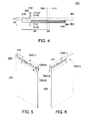
- FIG. 4 shows an explosion diagram of a multi-loop antenna structure of a first embodiment of the invention.
- FIG. 5 and FIG. 6 respectively show a 3-D diagram of a multi-loop antenna structure of a first embodiment of the invention viewed at different angles.
- the hand-held electronic device 30, such as a mobile phone, a personal digital assistant (PDA) and another communication device, includes a multi-loop antenna structure 310, an antenna carrying part 320 and a printed circuit board 330.
- the antenna carrying part 320 is coupled to the printed circuit board 330, and the multi-loop antenna structure 310 is disposed on the antenna carrying part 320.
- the multi-loop antenna structure 310 includes a feeding connecting part 312, a grounding connecting part 314, a similar U-shaped high-frequency radiating body 316 and a similar S-shaped low-frequency radiating body 318.
- the feeding connecting part 312 electrically connects one terminal of the high-frequency radiating body 316 and one terminal of the low-frequency radiating body 318 to a feeding point 3122.
- the grounding connecting part 314 grounds the other terminal of the high-frequency radiating body 316 and the other terminal of the low-frequency radiating body 318.
- the grounding connecting part 314 includes a grounding connecting element 3142, wherein one terminal 380 of the grounding connecting element 3142 connects the other terminal 390 of the high-frequency radiating body 316, the other terminal 390 of the low-frequency radiating body 318, and the other terminal of the grounding connecting element 3142 to a grounding point 31422.
- the feeding connecting part 312 forms a first folded loop antenna with the high-frequency radiating body 316 and the grounding connecting part 314 for resonating at a first frequency band.
- the feeding connecting part 312 forms a second folded loop antenna with the low-frequency radiating body 318 and the grounding connecting part 314 for resonating at a second frequency band, a third frequency band and a fourth frequency band.
- the resonating frequency operating at 0.5 times of the wavelength of the first folded loop antenna generates the first frequency band
- the resonating frequencies operating at 0.5, 1 and 1.5 times of the wavelength of the second folded loop antenna respectively generate the second frequency band, the third frequency band and the fourth frequency band.
- the first frequency band is a DCS/PCS/ UMTS frequency band ranging from 1710MHz to 2170MHz.
- the second frequency band is a GSM frequency band ranging from 824MHz to 960MHz.
- the third frequency band is a GPS frequency band of 1575MHz.
- the fourth frequency band is a Bluetooth and wireless network (BT/ WIFI) frequency band ranging from 2400MHz to 2500MHz.
- the first folded loop antenna and the second folded loop antenna are perpendicularly folded along the folding line 340, the folding line 350, the folding line 360 and the folding line 370 for forming a three-dimensional structure.
- the distances d1 and d4 are 5mm for example, the distance d2 is 11mm for example, and the distance d3 is 55mm for example.
- the antenna carrying part 320 includes a surface 320 (1), a surface 320 (2), a surface 320 (3) and a surface 320 (4), wherein the surfaces 320 (1), 320 (2), 320 (3) and 320 (4) are not coplanar to each other.
- the surface 320 (1) is perpendicular to the surfaces 320 (2), 320 (3) and 320 (4)
- the surface 320 (4) is perpendicular to the surfaces 320 (1), 320 (2) and 320 (3).
- the high-frequency radiating body 316 is perpendicularly folded along the folding line 350, so that a part of the high-frequency radiating body 316 is disposed on the surface 320 (1), and another part of the high-frequency radiating body 316 is disposed on surface 320 (2).
- the low-frequency radiating body 318 is perpendicularly folded along the folding line 360 and the folding line 370, so that a part of the low-frequency radiating body 318 is disposed on surface 320 (2), another part of the low-frequency radiating body 318 is disposed on surface 320 (4), and yet another part of the low-frequency radiating body 318 is disposed on the surface 320 (3).
- the feeding connecting part 312 is disposed on the surface 320 (2), and the grounding connecting part 314 is disposed on the surface 320 (3).
- One terminal 380 of the grounding connecting element 3142 and one terminal 390 of the low-frequency radiating body 318 are coupled to each other on the surface 320 (3).
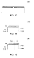
- FIG. 7 shows a generally known planar type first balance antenna.
- FIG. 8 shows an antenna of FIG. 7 being processed according to image theory for forming a loop antenna of the invention with reduced length.
- FIG. 9 shows an antenna of FIG. 8 being folded for forming a first folded loop antenna of the invention.
- One terminal of the high-frequency radiating body 316 is electrically connected to a feeding point 3122 through the feeding connecting part 312, and one terminal of the high-frequency radiating body 316 is electrically connected to the grounding point 31422 through the grounding connecting element 3142 of the grounding connecting part 314 for forming the first folded loop antenna 410 of FIG. 9 .
- the first folded loop antenna 410 corresponds to a generally known planar type first balance antenna 420 of FIG. 7 , which is a left-right-symmetric mapping structure. According to the image theory, the generally known planar type first balance antenna 420 is further reduced to the loop antenna 430 of FIG. 8 , so that the antenna length (can be viewed as a current path) of the loop antenna 430 is about a half of the generally known planar type first balance antenna 420.
- the first folded loop antenna 410 of FIG. 9 is formed by folding the grounding connecting element 3142 of the grounding connecting part 314 of the loop antenna 430 and the grounding point 31422 upwards. The first folded loop antenna 410 forms a three-dimensional structure when the first folded loop antenna 410 is perpendicularly folded along the folding line 340 and the folding line 350.
- FIG. 10 shows a generally known planar type second balance antenna.
- FIG. 11 shows an antenna of FIG. 10 being processed according to the image theory for forming a loop antenna of the invention with reduced length.
- FIG. 12 shows an antenna of FIG. 11 denoting the folding line of a second folded loop antenna of the subject application.
- One terminal of the low-frequency radiating body 318 is electrically connected to the feeding point 3122 through the feeding connecting part 312, and one terminal of the low-frequency radiating body 318 is electrically connected to t the grounding point 31422 through the grounding connecting element 3142 of the grounding connecting part 314 for forming the second folded loop antenna 440 of FIG. 12 .
- the second folded loop antenna 440 corresponds to the generally known planar type second balance antenna 450 of FIG. 10 , which is a left-right-symmetric mapping structure. According to the image theory, the second balance antenna 450 is further reduced to the loop antenna 460 of FIG. 11 , so that the antenna length (can be viewed as a current path) of the loop antenna 460 is about a half of the second balance antenna 450.
- the second folded loop antenna 440 of FIG. 12 is formed by folding the grounding connecting element 3142 of the grounding connecting part 314 of the loop antenna 460 and the grounding point 31422 rightwards. The second folded loop antenna 440 forms a three-dimensional structure when the second folded loop antenna 440 is perpendicularly folded along the folding line 360 and the folding line 370.
- the loop antenna was not commonly used in the hand-held electronic device, and the open end type antenna such as the planar inverted-F antenna (PIFA) was used instead.
- the subject application preferably reduces the length of the loop antenna to be half of its original length, and the reduced loop antenna is further folded as a three-dimensional structure, so that the loop antenna can be disposed on the hand-held device having limited space.
- the loop antenna can resonate at the operating frequency of 0.5, 1 and 1.5 times of the wavelength
- the subject application can resonate at several frequency bands by using one multi-loop antenna structure only.
- FIG. 13 shows a voltage standing wave ratio (VSWR) diagram of a multi-loop antenna structure 310 of the invention.
- FIG. 14 shows a return-loss diagram of a multi-loop antenna structure 310 of the invention.
- FIG. 15 shows a Smith chart of a multi-loop antenna structure 310 of the invention.
- the antenna effect of the multi-loop antenna structure 310 and the feature of resonating at a Bluetooth and wireless network (BT/WIFI) frequency band, a GSM frequency band, a GPS frequency band and a DCS/PCS/UMTS frequency band are indicated in FIG. 13 ⁇ FIG. 15 .
- BT/WIFI Bluetooth and wireless network
- FIG. 16 shows an explosion diagram of a multi-loop antenna structure of a second embodiment of the invention.
- FIG. 17 shows a 3-D diagram of a multi-loop antenna structure of a second embodiment of the invention.
- FIG. 18 shows a 3-D diagram of a multi-loop antenna structure of a second embodiment of the invention.
- the second embodiment differs with the first embodiment in that the high-frequency radiating body 316 and the low-frequency radiating body 318 of the multi-loop antenna structure 510 respectively have the grounding connecting elements 5142 and 5144, but the grounding connecting element 3142 is shared by the high-frequency radiating body 316 and the low-frequency radiating body 318 of the multi-loop antenna structure 310.
- the grounding connecting part 514 includes a grounding connecting element 5142 of the high-frequency radiating body 316 and a grounding connecting element 5144 of the low-frequency radiating body 318.
- One terminal of the grounding connecting element 5142 is connected to the other terminal of the high-frequency radiating body 316, and the other terminal of the grounding connecting element 5142 is connected to the grounding point 51422.
- One terminal of the grounding connecting element 5144 is connected to the other terminal of the low-frequency radiating body 318, and the other terminal of the grounding connecting element 5142 is connected to the grounding point 51442.
- the other terminal of the high-frequency radiating body 316 and the other terminal of the low-frequency radiating body 318 are respectively connected to the grounding point 51422 and the grounding point 51442 through the grounding connecting element 5142 and the grounding connecting element 5144.
- the bandwidth of the high-frequency frequency band is further increased.
- the commonly used index is -8db.
- FIG. 19 shows a voltage standing wave ratio (VSWR) diagram of a multi-loop antenna structure 510 of the subject application.
- FIG. 20 shows a return-loss diagram of a multi-loop antenna structure 510 of the subject application.
- FIG. 21 shows a Smith chart of a multi-loop antenna structure 510 of the subject application.
- the antenna effect of the multi-loop antenna structure 510 and the feature of resonating at a Bluetooth and wireless network (BT/WIFI) frequency band, a GSM frequency band, a GPS frequency band and a DCS/PCS/UMTS frequency band are indicated in FIG. 19 ⁇ FIG. 21 .
- BT/WIFI Bluetooth and wireless network
Landscapes
- Engineering & Computer Science (AREA)
- Computer Networks & Wireless Communication (AREA)
- Details Of Aerials (AREA)
- Support Of Aerials (AREA)
- Variable-Direction Aerials And Aerial Arrays (AREA)
Applications Claiming Priority (1)
| Application Number | Priority Date | Filing Date | Title |
|---|---|---|---|
| TW098113943A TWI378599B (en) | 2009-04-27 | 2009-04-27 | Multi-loop antenna structure and hand-held electronic device using the same |
Publications (1)
| Publication Number | Publication Date |
|---|---|
| EP2246935A1 true EP2246935A1 (fr) | 2010-11-03 |
Family
ID=41549873
Family Applications (1)
| Application Number | Title | Priority Date | Filing Date |
|---|---|---|---|
| EP10150776A Withdrawn EP2246935A1 (fr) | 2009-04-27 | 2010-01-14 | Structure d'antenne multi-boucles et appareil électronique portatif utilisant cette structure d'antenne |
Country Status (3)
| Country | Link |
|---|---|
| US (1) | US8259014B2 (fr) |
| EP (1) | EP2246935A1 (fr) |
| TW (1) | TWI378599B (fr) |
Cited By (1)
| Publication number | Priority date | Publication date | Assignee | Title |
|---|---|---|---|---|
| KR20200122227A (ko) * | 2019-04-17 | 2020-10-27 | 니혼 고꾸 덴시 고교 가부시끼가이샤 | 안테나 |
Families Citing this family (24)
| Publication number | Priority date | Publication date | Assignee | Title |
|---|---|---|---|---|
| US9070969B2 (en) | 2010-07-06 | 2015-06-30 | Apple Inc. | Tunable antenna systems |
| CN102386482B (zh) * | 2010-09-06 | 2014-06-18 | 光宝电子(广州)有限公司 | 多回圈天线系统及具有该多回圈天线系统的电子装置 |
| US9166279B2 (en) | 2011-03-07 | 2015-10-20 | Apple Inc. | Tunable antenna system with receiver diversity |
| US9246221B2 (en) | 2011-03-07 | 2016-01-26 | Apple Inc. | Tunable loop antennas |
| CN102856631B (zh) * | 2011-06-28 | 2015-04-22 | 财团法人工业技术研究院 | 天线与其通信装置 |
| DE102012109565A1 (de) | 2011-10-09 | 2013-04-18 | Beijing Lenovo Software Ltd. | Terminal-Einrichtung |
| CN103066374B (zh) * | 2011-10-24 | 2015-06-03 | 联想(北京)有限公司 | 缝隙结构天线装置和终端设备 |
| US9350069B2 (en) | 2012-01-04 | 2016-05-24 | Apple Inc. | Antenna with switchable inductor low-band tuning |
| US9190712B2 (en) | 2012-02-03 | 2015-11-17 | Apple Inc. | Tunable antenna system |
| JP5626483B2 (ja) * | 2012-06-08 | 2014-11-19 | 株式会社村田製作所 | アンテナおよび無線通信装置 |
| JP6004227B2 (ja) | 2012-09-13 | 2016-10-05 | パナソニックIpマネジメント株式会社 | アンテナ装置、無線通信装置、及び電子機器 |
| CN103151621B (zh) * | 2013-03-06 | 2015-12-09 | Tcl通讯(宁波)有限公司 | 一种四合一移动终端天线装置 |
| TWI509891B (zh) * | 2013-11-22 | 2015-11-21 | Wistron Neweb Corp | 迴圈天線 |
| US9799956B2 (en) | 2013-12-11 | 2017-10-24 | Dockon Ag | Three-dimensional compound loop antenna |
| US9748651B2 (en) * | 2013-12-09 | 2017-08-29 | Dockon Ag | Compound coupling to re-radiating antenna solution |
| CN110676574B (zh) | 2014-02-12 | 2021-01-29 | 华为终端有限公司 | 一种天线及移动终端 |
| CN105490000B (zh) | 2014-09-19 | 2018-06-19 | 深圳富泰宏精密工业有限公司 | 无线通信装置 |
| US20170149136A1 (en) * | 2015-11-20 | 2017-05-25 | Taoglas Limited | Eight-frequency band antenna |
| JP6285482B2 (ja) * | 2016-03-29 | 2018-02-28 | 株式会社フジクラ | フィルムアンテナ及びアンテナ装置 |
| CN110710055B (zh) * | 2017-06-27 | 2020-12-25 | 株式会社村田制作所 | 支持双频段天线装置 |
| CN109411877B (zh) * | 2017-08-17 | 2020-11-17 | 元太科技工业股份有限公司 | 天线装置以及电子设备 |
| CN116722341B (zh) * | 2020-06-04 | 2024-06-04 | 华为技术有限公司 | 一种电子设备 |
| TWI786462B (zh) * | 2020-11-09 | 2022-12-11 | 緯創資通股份有限公司 | 天線模組及電子裝置 |
| CN114552173B (zh) * | 2020-11-25 | 2024-05-14 | 北京小米移动软件有限公司 | 天线结构和电子设备 |
Citations (3)
| Publication number | Priority date | Publication date | Assignee | Title |
|---|---|---|---|---|
| EP1555715A1 (fr) * | 2004-01-13 | 2005-07-20 | Kabushiki Kaisha Toshiba | Dispositif d'antenne et terminal mobile sans fil équipé d'un tel dispositif |
| JP2007088975A (ja) * | 2005-09-26 | 2007-04-05 | Toshiba Corp | 無線装置 |
| US20080169981A1 (en) * | 2007-01-16 | 2008-07-17 | Kabushiki Kaisha Toshiba | Antenna device operable in multiple frequency bands |
Family Cites Families (4)
| Publication number | Priority date | Publication date | Assignee | Title |
|---|---|---|---|---|
| US7113135B2 (en) * | 2004-06-08 | 2006-09-26 | Skycross, Inc. | Tri-band antenna for digital multimedia broadcast (DMB) applications |
| JP4311576B2 (ja) | 2005-11-18 | 2009-08-12 | ソニー・エリクソン・モバイルコミュニケーションズ株式会社 | 折り返しダイポールアンテナ装置および携帯無線端末 |
| JP4231867B2 (ja) * | 2005-11-18 | 2009-03-04 | 株式会社東芝 | 無線装置および電子機器 |
| WO2009142756A2 (fr) * | 2008-05-22 | 2009-11-26 | California Institute Of Technology | Antennes sur puce très efficaces et utilisant un couplage résonnant fort |
-
2009
- 2009-04-27 TW TW098113943A patent/TWI378599B/zh not_active IP Right Cessation
- 2009-12-10 US US12/634,704 patent/US8259014B2/en not_active Expired - Fee Related
-
2010
- 2010-01-14 EP EP10150776A patent/EP2246935A1/fr not_active Withdrawn
Patent Citations (3)
| Publication number | Priority date | Publication date | Assignee | Title |
|---|---|---|---|---|
| EP1555715A1 (fr) * | 2004-01-13 | 2005-07-20 | Kabushiki Kaisha Toshiba | Dispositif d'antenne et terminal mobile sans fil équipé d'un tel dispositif |
| JP2007088975A (ja) * | 2005-09-26 | 2007-04-05 | Toshiba Corp | 無線装置 |
| US20080169981A1 (en) * | 2007-01-16 | 2008-07-17 | Kabushiki Kaisha Toshiba | Antenna device operable in multiple frequency bands |
Cited By (1)
| Publication number | Priority date | Publication date | Assignee | Title |
|---|---|---|---|---|
| KR20200122227A (ko) * | 2019-04-17 | 2020-10-27 | 니혼 고꾸 덴시 고교 가부시끼가이샤 | 안테나 |
Also Published As
| Publication number | Publication date |
|---|---|
| US8259014B2 (en) | 2012-09-04 |
| US20100271271A1 (en) | 2010-10-28 |
| TW201039493A (en) | 2010-11-01 |
| TWI378599B (en) | 2012-12-01 |
Similar Documents
| Publication | Publication Date | Title |
|---|---|---|
| EP2246935A1 (fr) | Structure d'antenne multi-boucles et appareil électronique portatif utilisant cette structure d'antenne | |
| EP1788663B1 (fr) | Antenne doublet replié et terminal mobile de radiocommunication | |
| US6943733B2 (en) | Multi-band planar inverted-F antennas including floating parasitic elements and wireless terminals incorporating the same | |
| US8330666B2 (en) | Multiband antenna | |
| US9502770B2 (en) | Compact multiple-band antenna for wireless devices | |
| US8922449B2 (en) | Communication electronic device and antenna structure thereof | |
| US20050110692A1 (en) | Multiband planar built-in radio antenna with inverted-l main and parasitic radiators | |
| CN102099962B (zh) | 天线结构 | |
| CN101297440A (zh) | 多波段天线设备和通信终端装置 | |
| JP4446203B2 (ja) | アンテナ素子および広帯域アンテナ装置 | |
| US7965239B2 (en) | Antenna structure | |
| CN101740859B (zh) | 多频带天线 | |
| US7391375B1 (en) | Multi-band antenna | |
| JP6414786B2 (ja) | 携帯通信端末および筐体カバー | |
| EP1345282B1 (fr) | Antenne intégrée multibande composée d'éléments d'antennes planaires principale et parasites en "l" inversé | |
| EP2026412A1 (fr) | Antenne de bande large et dispositif électronique correspondant | |
| US20120056797A1 (en) | Frequency-tunable antenna | |
| CN101242034B (zh) | 小型化的多频天线 | |
| US20050237245A1 (en) | Antenna device | |
| CN101997159B (zh) | 天线模块及其应用的电子装置 | |
| CN106207400A (zh) | 宽频单极型天线、电子装置、以及天线模块 | |
| US20100079349A1 (en) | Parasitic antenna | |
| EP1653561A1 (fr) | Antenne integrée d'un terminal mobile | |
| JP2011155591A (ja) | マルチバンド対応アンテナ、及び該アンテナを有する携帯無線機 | |
| WO2020239544A1 (fr) | Système d'antenne |
Legal Events
| Date | Code | Title | Description |
|---|---|---|---|
| PUAI | Public reference made under article 153(3) epc to a published international application that has entered the european phase |
Free format text: ORIGINAL CODE: 0009012 |
|
| 17P | Request for examination filed |
Effective date: 20100114 |
|
| AK | Designated contracting states |
Kind code of ref document: A1 Designated state(s): AT BE BG CH CY CZ DE DK EE ES FI FR GB GR HR HU IE IS IT LI LT LU LV MC MK MT NL NO PL PT RO SE SI SK SM TR |
|
| 17Q | First examination report despatched |
Effective date: 20130726 |
|
| RAP1 | Party data changed (applicant data changed or rights of an application transferred) |
Owner name: HTC CORPORATION |
|
| APBK | Appeal reference recorded |
Free format text: ORIGINAL CODE: EPIDOSNREFNE |
|
| APBN | Date of receipt of notice of appeal recorded |
Free format text: ORIGINAL CODE: EPIDOSNNOA2E |
|
| APBR | Date of receipt of statement of grounds of appeal recorded |
Free format text: ORIGINAL CODE: EPIDOSNNOA3E |
|
| APAF | Appeal reference modified |
Free format text: ORIGINAL CODE: EPIDOSCREFNE |
|
| STAA | Information on the status of an ep patent application or granted ep patent |
Free format text: STATUS: EXAMINATION IS IN PROGRESS |
|
| APBT | Appeal procedure closed |
Free format text: ORIGINAL CODE: EPIDOSNNOA9E |
|
| STAA | Information on the status of an ep patent application or granted ep patent |
Free format text: STATUS: THE APPLICATION IS DEEMED TO BE WITHDRAWN |
|
| 18D | Application deemed to be withdrawn |
Effective date: 20200801 |