EP2247076B1 - Verfahren und Vorrichtung zur logischen Volumenverwaltung - Google Patents
Verfahren und Vorrichtung zur logischen Volumenverwaltung Download PDFInfo
- Publication number
- EP2247076B1 EP2247076B1 EP09252089.9A EP09252089A EP2247076B1 EP 2247076 B1 EP2247076 B1 EP 2247076B1 EP 09252089 A EP09252089 A EP 09252089A EP 2247076 B1 EP2247076 B1 EP 2247076B1
- Authority
- EP
- European Patent Office
- Prior art keywords
- logical unit
- lun
- storage
- storage subsystem
- wwpn
- Prior art date
- Legal status (The legal status is an assumption and is not a legal conclusion. Google has not performed a legal analysis and makes no representation as to the accuracy of the status listed.)
- Not-in-force
Links
Images


Classifications
-
- H—ELECTRICITY
- H04—ELECTRIC COMMUNICATION TECHNIQUE
- H04L—TRANSMISSION OF DIGITAL INFORMATION, e.g. TELEGRAPHIC COMMUNICATION
- H04L67/00—Network arrangements or protocols for supporting network services or applications
- H04L67/01—Protocols
- H04L67/10—Protocols in which an application is distributed across nodes in the network
- H04L67/1097—Protocols in which an application is distributed across nodes in the network for distributed storage of data in networks, e.g. transport arrangements for network file system [NFS], storage area networks [SAN] or network attached storage [NAS]
-
- G—PHYSICS
- G06—COMPUTING OR CALCULATING; COUNTING
- G06F—ELECTRIC DIGITAL DATA PROCESSING
- G06F3/00—Input arrangements for transferring data to be processed into a form capable of being handled by the computer; Output arrangements for transferring data from processing unit to output unit, e.g. interface arrangements
- G06F3/06—Digital input from, or digital output to, record carriers, e.g. RAID, emulated record carriers or networked record carriers
- G06F3/0601—Interfaces specially adapted for storage systems
- G06F3/0602—Interfaces specially adapted for storage systems specifically adapted to achieve a particular effect
- G06F3/0604—Improving or facilitating administration, e.g. storage management
- G06F3/0605—Improving or facilitating administration, e.g. storage management by facilitating the interaction with a user or administrator
-
- G—PHYSICS
- G06—COMPUTING OR CALCULATING; COUNTING
- G06F—ELECTRIC DIGITAL DATA PROCESSING
- G06F3/00—Input arrangements for transferring data to be processed into a form capable of being handled by the computer; Output arrangements for transferring data from processing unit to output unit, e.g. interface arrangements
- G06F3/06—Digital input from, or digital output to, record carriers, e.g. RAID, emulated record carriers or networked record carriers
- G06F3/0601—Interfaces specially adapted for storage systems
- G06F3/0602—Interfaces specially adapted for storage systems specifically adapted to achieve a particular effect
- G06F3/0614—Improving the reliability of storage systems
- G06F3/0619—Improving the reliability of storage systems in relation to data integrity, e.g. data losses, bit errors
-
- G—PHYSICS
- G06—COMPUTING OR CALCULATING; COUNTING
- G06F—ELECTRIC DIGITAL DATA PROCESSING
- G06F3/00—Input arrangements for transferring data to be processed into a form capable of being handled by the computer; Output arrangements for transferring data from processing unit to output unit, e.g. interface arrangements
- G06F3/06—Digital input from, or digital output to, record carriers, e.g. RAID, emulated record carriers or networked record carriers
- G06F3/0601—Interfaces specially adapted for storage systems
- G06F3/0628—Interfaces specially adapted for storage systems making use of a particular technique
- G06F3/0638—Organizing or formatting or addressing of data
- G06F3/0644—Management of space entities, e.g. partitions, extents, pools
-
- G—PHYSICS
- G06—COMPUTING OR CALCULATING; COUNTING
- G06F—ELECTRIC DIGITAL DATA PROCESSING
- G06F3/00—Input arrangements for transferring data to be processed into a form capable of being handled by the computer; Output arrangements for transferring data from processing unit to output unit, e.g. interface arrangements
- G06F3/06—Digital input from, or digital output to, record carriers, e.g. RAID, emulated record carriers or networked record carriers
- G06F3/0601—Interfaces specially adapted for storage systems
- G06F3/0628—Interfaces specially adapted for storage systems making use of a particular technique
- G06F3/0646—Horizontal data movement in storage systems, i.e. moving data in between storage devices or systems
- G06F3/0647—Migration mechanisms
-
- G—PHYSICS
- G06—COMPUTING OR CALCULATING; COUNTING
- G06F—ELECTRIC DIGITAL DATA PROCESSING
- G06F3/00—Input arrangements for transferring data to be processed into a form capable of being handled by the computer; Output arrangements for transferring data from processing unit to output unit, e.g. interface arrangements
- G06F3/06—Digital input from, or digital output to, record carriers, e.g. RAID, emulated record carriers or networked record carriers
- G06F3/0601—Interfaces specially adapted for storage systems
- G06F3/0668—Interfaces specially adapted for storage systems adopting a particular infrastructure
- G06F3/067—Distributed or networked storage systems, e.g. storage area networks [SAN], network attached storage [NAS]
-
- H—ELECTRICITY
- H04—ELECTRIC COMMUNICATION TECHNIQUE
- H04L—TRANSMISSION OF DIGITAL INFORMATION, e.g. TELEGRAPHIC COMMUNICATION
- H04L2101/00—Indexing scheme associated with group H04L61/00
- H04L2101/60—Types of network addresses
- H04L2101/618—Details of network addresses
- H04L2101/645—Fibre channel identifiers
Definitions
- This invention relates in general to storage technology and more specifically to methods and systems related to the logical volume management of a storage subsystem, and especially SAN (Storage Area Network).
- SAN Storage Area Network
- the storage subsystem in SAN has one or more logical volumes, called the LU (Logical Unit).
- the host in SAN connects to a storage subsystem and accesses the LU in order to read / write data.
- Each LU has its own identification data to identify itself. For instance, the host typically requires ID information from the LU to connect with it properly. There are two typical IDs for the LU.
- Each physical port of storage subsystem has its own WWPN (World Wide Port Name).
- the WWPN is used for identification for the physical port and every LU can be accessed via the physical port using WWPN.
- Each physical port has one or more LUs and each LU has a number to identify itself. This identifier is called the LUN (Logical Unit Number).
- Each LU has its own identifier based on the storage controller WWN (World Wide Name).
- WWN World Wide Name
- the storage controller which creates this LU gives the LU an identifier.
- the identifier is made by the combination WWN of the storage controller and the timestamp of the LU's creation.
- the LU migration requires a storage administrator to create a new LU.
- the LUN ID of this new LU will be different from the old LU.
- the LUN ID will be changed despite the LUs having same data (the old LU will be deleted after migration process).
- LU mirroring also requires the storage administrator to create a new LU. This results in the same problem that occurs with migration (same data, different LUN ID).
- US 2006/265529 discloses a storage router having an internet protocol (IP) port for coupling to a network supporting IP packets, a fibre channel port for coupling to a fibre channel network to a plurality of storage devices, and a SCSI router having an iSCSI interface that extracts SCSI command and data information from packets received through the IP port, wherein the SCSI router passes the extracted SCSI command and data information to the fiber channel port.
- IP internet protocol
- US7293152 discloses a technique which enables efficient access to logical unit numbers (luns) or virtual disks (vdisks) stored on a storage system, such as a multi-protocol storage appliance.
- the technique allows a grouping of initiators by a "human friendly" logical name that is mapped to a lun or vdisk on the storage appliance.
- the inventive methodology is directed to methods and systems that substantially obviate one or more of the above and other problems associated with consistency between data and the LU identification.
- the present invention provides a system as set forth in the appended claims, and a method of controlling a storage system as set forth in the appended claims.
- a storage subsystem comprising a storage controller and a plurality of logical units; a storage area network; a host computer connected to the storage area network; a management server connected to the storage subsystem, the storage area network and the host computer; wherein the storage controller further comprises instructions for migrating a source logical unit with a physical logical unit number ID (LUN ID), the instructions executing a process including creating a target logical unit; migrating the source logical unit into the target logical unit; maintaining the target logical unit as a mirror of the source logical unit; and wherein if the source logical unit fails, migrating the physical LUN ID of the source logical unit to the target logical unit.
- LUN ID physical logical unit number ID
- a storage subsystem comprising a storage controller and a plurality of logical units; a storage area network; a host computer connected to the storage area network; a management server connected to the storage subsystem, the storage area network and the host computer; wherein the storage controller further comprises instructions for migrating a source logical unit with a physical logical unit number ID (LUN ID) and a virtual LUN ID, the instructions executing a process including creating a target logical unit; creating a physical LUN ID for the target logical unit; and migrating the source logical unit and the virtual LUN ID of the source logical unit into the target logical unit.
- LUN ID physical logical unit number ID
- the instructions executing a process including creating a target logical unit; creating a physical LUN ID for the target logical unit; and migrating the source logical unit and the virtual LUN ID of the source logical unit into the target logical unit.
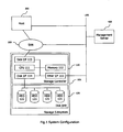
- Fig. 1 illustrates an exemplary system configuration of the present invention.
- Fig. 2 illustrates functions executed by application programs.
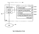
- Fig. 3 illustrates an exemplary configuration of the Host Computer.
- Fig. 4 illustrates an exemplary configuration of the Management Server.
- Fig. 5 illustrates an exemplary embodiment of a system configuration.
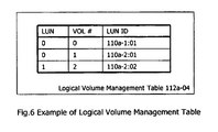
- Fig. 6 illustrates an exemplary embodiment of the logical volume management table.
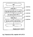
- Fig. 7 illustrates the migration process with LUN ID.
- Fig. 8a and Fig. 8b illustrates an exemplary embodiment of the logical volume management table after the migration process.
- Fig. 9 illustrates another exemplary embodiment of a system configuration.
- Fig. 10 illustrates an exemplary embodiment of the LUN ID mapping table.
- Fig. 11 illustrates a an exemplary embodiment of the migration process with LUN ID and how the LUN ID mapping table is updated.
- Fig. 12 illustrates the response method to a SCSI inquiry command for LU.
- Fig. 13 illustrates another example of a possible system configuration.
- Fig. 14a and 14b illustrates an exemplary embodiment of a LUN ID mapping table.
- Fig. 15 illustrates how the storage subsystem generates a virtual LUN ID and a physical LUN ID for each LU.
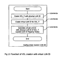
- Fig. 16 illustrates an exemplary embodiment of the migration process when using virtual LUN ID.
- Fig. 17 illustrates another exemplary embodiment of a system configuration.
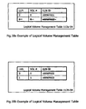
- Fig. 18a and 18b illustrates an exemplary embodiment of logical volume management table using WWPN as LUN ID.
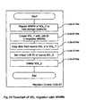
- Fig. 19 illustrates an exemplary embodiment of the migration process using virtual WWPN.
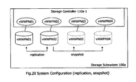
- Fig. 20 illustrates an exemplary system configuration along with the replication volume and snapshot volume to be adopted.
- Fig. 21 illustrates an exemplary embodiment of searching for an LU using query.
- Fig. 22 illustrates an exemplary embodiment of the LUN ID mapping table.
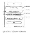
- Fig. 23 illustrates the LUN ID migration process when using mirroring and replication.
- Fig. 24 illustrates an exemplary embodiment of a computer platform upon which the inventive system may be implemented.
- the inventive system comprises at least a storage subsystem, host computer and SAN (Storage Area Network).
- LU_1 (Logical Unit) of the storage subsystem has its own physical LUN ID.
- LU_1 a source logical unit
- LU_2 a target logical unit
- the storage subsystem creates LU_2 and sets LUN ID of LU_1 after copying data from LU_1 to LU_2 and deleting LU_1.
- LU_2 can be managed by the same storage subsystem as LU_1's one and/or another storage subsystem.
- the disclosed system comprises at least a storage subsystem, host computer and SAN (Storage Area Network).
- LU_1 (Logical Unit) of storage subsystem has its own physical LUN ID.
- LU_1 a source logical unit
- LU_2 a target logical unit
- the storage subsystem creates LU_2 and also creates its own LUN ID.
- the storage subsystem then associates the LUN ID of LU_1 and LUN ID of LU_2 after migration process.
- storage subsystem receives SCSI inquiry command for LU_2, it sends the LUN ID of LU_1 instead of original LUN ID of LU_2.
- LU_2 can be managed by same storage subsystem as LU_1's one and/or another storage subsystem.
- the inventive system comprises at least storage subsystem, host computer and SAN (Storage Area Network).
- storage subsystem creates LU (Logical Unit), it creates physical LUN ID and virtual LUN ID.
- LU_1 a source logical unit
- LU_2 a target logical unit
- the storage subsystem creates LU_2 with physical LUN ID and set virtual LUN ID of LU_1 after copying data from LU_1 to LU_2 and deleting LU_1.
- storage subsystem receives SCSI inquiry command for LU_2, it sends LUN ID of LU_1 instead of original LUN ID of LU_2.
- LU_2 can be managed by same storage subsystem as LU_1's one and/or another storage subsystem.
- the inventive system comprises at least a storage subsystem, host computer and SAN (Storage Area Network).
- LU Logical Unit
- the storage subsystem creates virtual WWPN for the access port of this LU and LUN ID using its virtual WWPN.
- LU_1 a source logical unit
- LU_2 a target logical unit
- storage subsystem migrates and associates virtual WWPN of LU_1 with LU_2, and then creates LUN ID using migrated virtual WWPN.
- LU 2 can be managed by same storage subsystem as LU_1's one and/or another storage subsystem.
- the inventive system comprises at least a storage subsystem, host computer and SAN (Storage Area Network).
- the storage subsystem has a mapping table between LUN ID and the metadata of LU.
- host computer sends a search query
- storage subsystem responses proper LUN ID by matching the search query with metadata.
- the management server can also execute this process.
- the disclosed system comprises at least a storage subsystem, host computer and SAN (Storage Area Network).
- LU_1 and LU_2 are mirrored (replicated) to each other, and when LU_1 is destroyed by disaster or due to other causes, the storage subsystem sets the LUN ID of LU_1 to LU_2.
- Fig.1 shows system configuration of an embodiment of the invention. It includes a Storage Subsystem 100, a SAN-SW 200, a Host Computer 300 and a Management Server 400.
- the Storage Subsystem 100 has a Storage Controller 110 and a Disk Unit 120.
- the Storage Controller can include a SAN I/F 113, a CPU 111, Memory 112 and an Ethernet I/F 115.
- the Storage Controller performs disk I/O functions with the Host Computer 300 by using a Fibre Channel Protocol via the SAN 200.
- the Disk Unit 120 has a plurality of Hard Disk Drives (HDD) 121 and the Storage Controller combines these HDDs and configures RAID (Redundant Arrays of Inexpensive Disks), and then provides Volume (LU: Logical Unit) to the Host Computer 300.
- HDD Hard Disk Drives
- RAID Redundant Arrays of Inexpensive Disks
- LU Logical Unit
- Fig. 2 illustrates an example software module configuration on the storage controller. This can include Logical Volume I/O Control 112-01, Physical Disk Control 112-02, Flush Cache Control 112-03, a Logical Volume Management Table 112-04, a RAID Management Table 112-05, Configuration Control 112-06, Migration Control 112-07, LUN ID Mapping Table 112-08, LUN ID Metadata Control 112-09, LUN ID Metadata Table 112-10, and Mirroring Control 112-11.
- Logical Volume I/O Control 112-01 Physical Disk Control 112-02, Flush Cache Control 112-03, a Logical Volume Management Table 112-04, a RAID Management Table 112-05, Configuration Control 112-06, Migration Control 112-07, LUN ID Mapping Table 112-08, LUN ID Metadata Control 112-09, LUN ID Metadata Table 112-10, and Mirroring Control 112-11.
- Fig.3 shows the configuration of the Host Computer 300.
- the Host Computer 300 connects to the SAN 200.
- the Host Computer 300 also contains a Hypervisor program for the Virtual Machine which enables the physical Host Computer 300 to run multiple virtual server machine images (VM). Each VM has I/O connections to the Storage Subsystem 100.
- the Host Computer itself can include an Ethernet I/F 304, CPU 301, and a Host Bust Adapter (HBA) 303.
- the Memory 302 of the Host Computer can include an Operating System 302-01, the aforementioned Hypervisor Program for the Virtual Machine 302-02, I/O Control 302-03, and a Storage Path Management Table 302-04.
- Fig.4 shows the configuration of the Management Server 400. It connects to the Storage Subsystem 100, the SAN 200 and the Host Computer 300 via LAN to control them.
- the Management Server itself may include an Ethernet I/F 403 and CPU 401.
- the Memory 402 of the Management Server can include an Operating System 402-01, a LUN ID Proxy 402-02, a LUN ID Mapping Table 402-03, LUN ID Metadata Control 402-04, and a LUN ID Metadata Table 402-05.
- LU_1 Logical Unit
- the storage subsystem creates LU_2 and sets LUN ID of LU_1 after copying data from LU_1 to LU_2 and deleting LU_1.
- LU_2 can thus be managed by the same storage subsystem as LU_1's one and/or another storage subsystem.
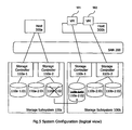
- Fig. 5 shows an example system configuration.
- the Host and / or the Virtual Machine (VM) 501, 502 connect to the storage subsystem 100, access to the logical volume (shown as "110a-a:01", for instance).
- "110a-a:01” is by LUN ID generated by the storage controller 110a-1 using its WWN (World Wide Name) and timestamp, for example.
- Fig. 6 shows the example of logical volume management table 112a-04. It manages the mapping between LUN and VOL # and LUN ID. This time, the data of logical volume "110a-2:02" will be migrated to "110b-01:01".
- Fig.7 shows the migration process with LUN ID. This process is executed by migration control 112b-07 on the storage subsystem 100b, for instance.
- VOL_S represents the source LU for migration
- VOL_T represents the target LU for migration.
- VOL_S represents the source LU for migration
- VOL_T represents the target LU for migration.
- VOL_S represents the source LU for migration
- VOL_T represents the target LU for migration.
- VOL_S represents the source LU for migration
- VOL_T represents the target LU for migration.
- it copies the data 112b-07-01b of "110a-2:02" to "110b-1:01" and deletes 112b-07-01d LU "110a-2:02" after the copying process.
- Fig. 8a and 8b shows the example of logical volume management table 112a-04 112b-04 after this migration process.
- this example illustrates the inter storage subsystem environment.
- the Old LU and the new LU can be placed on the same storage subsystem as well.
- LU_1 Logical Unit
- the storage subsystem creates LU_2 and also creates its own LUN ID.
- the storage subsystem associates the LUN ID of LU_1 and the LUN ID of LU_2 after the migration process.
- the storage subsystem receives a SCSI inquiry command for LU_2, it sends the LUN ID of LU_1 instead of the original LUN ID of LU_2.
- Fig.9 shows the example of system configuration.
- "110a-a:01” is a LUN ID generated by storage controller 110a-1 using its WWN (World Wide Name) and timestamp, for instance.
- WWN World Wide Name
- the data of logical volume "110a-2:02” will be migrated to "110b-01:01”.
- LUN ID "110a-2:02” will be migrated to the storage subsystem and associated with the LUN ID "110b-01:01”. This association can be managed by the LUN ID mapping table 112b-08 (shown in Fig.10 ).
- Fig.11 shows the migration process with LUN ID and how the LUN ID mapping table is updated.
- This process is executed by migration control 112b-07 on the storage subsystem 100b, for instance. At first, it creates 112b-07-02a LU "110b-1:01 ", the target LU for migration. Next, it copies the data of "110a-2:02" to "110b-1:01" 112b-07-02b, acquires the LUN ID of the source LU 112b-07-02c and deletes 112b-07-02d LU "110a-2:02" after the copying process completes. Then, it adds new mapping information between 112b-07-02e LUN ID "110b-1:01" and "110a-2:02".
- Fig.12 shows the response method to a SCSI inquiry command for LU from the Logical Volume I/O Control 112b-01.
- the host issues a SCSI inquiry command 112b-01-01a to obtain the condition of the LU, including the LUN ID.
- the conventional method is for the storage subsystem to respond 112b-01-01e with the physical LUN ID 112b-01-01d.
- a SCSI inquiry command for LU "110b-1:01" means that the storage subsystem sends a response with LUN ID "110b-1:01".
- this invention refers to the LUN ID mapping table 112b-01-01 b instead and thus sends LUN ID "110a-2:02" 112b-01-01 c instead of "110b-1:01".
- Fig.13 shows another example of a system configuration.
- Each LU has its own physical LUN ID and virtual LUN ID as well.
- the virtual LUN ID will be migrated with the actual data, and the storage subsystem sends the virtual LUN ID in response to a SCSI inquiry.
- Fig.14a and 14b shows the example of LUN ID mapping table 112a-08, 112b-08.
- the storage subsystem When a new LU is created 112b-06-02a (including replication and/or snapshot), the storage subsystem generates a virtual LUN ID 112b-06-02b and a physical LUN ID for each LU (shown as Fig.15 in the configuration control 112b-06) 112b-06-02c.
- Fig.16 shows the migration process when using virtual LUN ID, as done by the migration control 112b-07.
- a target volume is created with a physical LUN ID 112b-07-03a.
- data is copied from the source volume to the target volume 112b-07-03b.
- the virtual LUN ID of the source volume is acquired 112b-07-03c.
- the source volume is deleted 112b-07-03d, and the LUN ID mapping table is updated 112b-07-03e.
- This example also shows an example of the inter storage subsystem environment.
- the old LU and the new LU can be placed on same storage subsystem as well.
- This invention allows the storage subsystem to use a virtual WWPN (World Wide Port Name) as a LUN ID.
- a NPIV N_Port ID Virtualization
- the storage subsystem creates a LU (Logical Unit), it creates a virtual WWPN for an access port of this LU.
- the LUN ID will be generated by using its virtual WWPN (or same as virtual WWPN).
- LU_1 is migrated into LU_2, the storage subsystem migrates and associates virtual WWPN of LU_1 with LU_2, and then creates a LUN ID using the migrated virtual WWPN.
- Fig.17 shows the example of system configuration.
- "vWWPN01” is LUN ID generated by storage controller 110a-1. It is also a virtual WWPN for LU access.
- One LU has one or more virtual WWPNs for access port and LUN ID (if it has two WWPN, it can be used for multiple path).
- Fig.18a and 18b shows an example of the logical volume management table 112a-04, 112b-04 using WWPN as LUN ID.
- Fig.19 shows the migration process using virtual WWPN.
- This process is executed by migration control 112b-07 on storage subsystem 100b, for instance.
- migration control 112b-07 migrates 112b-07-04a the virtual WWPN to a new storage controller and creates a new LU 112b-07-04b for migration.
- This virtual WWPN migration lets the new storage controller create a new LUN ID 112b-07-04d based on the migrated virtual WWPN (same LUN ID will be generated).
- the processes of copying data 112b-07-04c and of deleting LU 112b-07-04e will be executed.
- the virtual WWPN will be created when the new volume is created (This mean that each volume has its own virtual WWPN for access and identification). Shown as Fig. 20 , the replication volume and snapshot volume will be adopted as well. When the new replication/snapshot volume is created, the virtual WWPN for it will be created as well.
- the Old LU and new LU can be placed on same storage subsystem as well.
- Fig. 21 shows the example of searching LU using query.
- Fig. 22 shows an example of the LUN ID mapping table 112b-10.
- the administrator can input metadata for each LU.
- the administrator can the search LU by using search words such as "host 300", "backup” and so on.
- Fig.23 shows the LUN ID migration process when using mirroring and replication 112b-11. This process is executed by migration control 112b-07 on storage subsystem 100b, for instance. If it detects the failure of LU_1, the LUN ID migration of LU_1 to LU_2 will occur. First the LUN ID of the source volume is acquired 112b-11-01 a. Then the source volume and the target volume are maintained as mirrors 112b-11-01b. If a disaster occurs such that the source volume no longer responds 112b-11-01 c, then the target volume will have the LUN ID of the source volume 112b-11-01d.
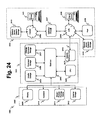
- Figure 24 is a block diagram that illustrates an embodiment of a computer/server system 2400 upon which an embodiment of the inventive methodology may be implemented.
- the system 2400 includes a computer/server platform 2401, peripheral devices 2402 and network resources 2403.
- the computer platform 2401 may include a data bus 2404 or other communication mechanism for communicating information across and among various parts of the computer platform 2401, and a processor 2405 coupled with bus 2401 for processing information and performing other computational and control tasks.
- Computer platform 2401 also includes a volatile storage 2406, such as a random access memory (RAM) or other dynamic storage device, coupled to bus 2404 for storing various information as well as instructions to be executed by processor 2405.
- RAM random access memory
- the volatile storage 2406 also may be used for storing temporary variables or other intermediate information during execution of instructions by processor 2405.
- Computer platform 2401 may further include a read only memory (ROM or EPROM) 2407 or other static storage device coupled to bus 2404 for storing static information and instructions for processor 2405, such as basic input-output system (BIOS), as well as various system configuration parameters.
- ROM read only memory
- EPROM electrically erasable read-only memory
- a persistent storage device 2408 such as a magnetic disk, optical disk, or solid-state flash memory device is provided and coupled to bus 2401 for storing information and instructions.
- Computer platform 2401 may be coupled via bus 2404 to a display 2409, such as a cathode ray tube (CRT), plasma display, or a liquid crystal display (LCD), for displaying information to a system administrator or user of the computer platform 2401.
- a display 2409 such as a cathode ray tube (CRT), plasma display, or a liquid crystal display (LCD), for displaying information to a system administrator or user of the computer platform 2401.
- An input device 2410 is coupled to bus 2401 for communicating information and command selections to processor 2405.
- cursor control device 2411 such as a mouse, a trackball, or cursor direction keys for communicating direction information and command selections to processor 2404 and for controlling cursor movement on display 2409.
- This input device typically has two degrees of freedom in two axes, a first axis (e.g., x) and a second axis (e.g., y), that allows the device to specify positions in a plane.
- An external storage device 2412 may be coupled to the computer platform 2401 via bus 2404 to provide an extra or removable storage capacity for the computer platform 2401.
- the external removable storage device 2412 may be used to facilitate exchange of data with other computer systems.
- the invention is related to the use of computer system 2400 for implementing the techniques described herein.
- the inventive system may reside on a machine such as computer platform 2401.
- the techniques described herein are performed by computer system 2400 in response to processor 2405 executing one or more sequences of one or more instructions contained in the volatile memory 2406.
- Such instructions may be read into volatile memory 2406 from another computer-readable medium, such as persistent storage device 2408.
- Execution of the sequences of instructions contained in the volatile memory 2406 causes processor 2405 to perform the process steps described herein.
- hard-wired circuitry may be used in place of or in combination with software instructions to implement the invention.
- embodiments of the invention are not limited to any specific combination of hardware circuitry and software.
- Non-volatile media includes, for example, optical or magnetic disks, such as storage device 2408.
- Volatile media includes dynamic memory, such as volatile storage 2406.
- Computer-readable media include, for example, a floppy disk, a flexible disk, hard disk, magnetic tape, or any other magnetic medium, a CD-ROM, any other optical medium, punchcards, papertape, any other physical medium with patterns of holes, a RAM, a PROM, an EPROM, a FLASH-EPROM, a flash drive, a memory card, any other memory chip or cartridge, or any other medium from which a computer can read.
- Various forms of computer readable media may be involved in carrying one or more sequences of one or more instructions to processor 2405 for execution.
- the instructions may initially be carried on a magnetic disk from a remote computer.
- a remote computer can load the instructions into its dynamic memory and send the instructions over a telephone line using a modem.
- a modem local to computer system 2400 can receive the data on the telephone line and use an infra-red transmitter to convert the data to an infra-red signal.
- An infra-red detector can receive the data carried in the infra-red signal and appropriate circuitry can place the data on the data bus 2404.
- the bus 2404 carries the data to the volatile storage 2406, from which processor 2405 retrieves and executes the instructions.
- the instructions received by the volatile memory 2406 may optionally be stored on persistent storage device 2408 either before or after execution by processor 2405.
- the instructions may also be downloaded into the computer platform 2401 via Internet using a variety of network data communication protocols well known in the art.
- the computer platform 2401 also includes a communication interface, such as network interface card 2413 coupled to the data bus 2404.
- Communication interface 2413 provides a two-way data communication coupling to a network link 2414 that is coupled to a local network 2415.
- communication interface 2413 may be an integrated services digital network (ISDN) card or a modem to provide a data communication connection to a corresponding type of telephone line.
- ISDN integrated services digital network
- communication interface 2413 may be a local area network interface card (LAN NIC) to provide a data communication connection to a compatible LAN.
- Wireless links such as well-known 802.11 a, 802.11 b, 802.11 g and Bluetooth may also used for network implementation.
- communication interface 2413 sends and receives electrical, electromagnetic or optical signals that carry digital data streams representing various types of information.
- Network link 2413 typically provides data communication through one or more networks to other network resources.
- network link 2414 may provide a connection through local network 2415 to a host computer 2416, or a network storage/server 2417.
- the network link 2413 may connect through gateway/firewall 2417 to the wide-area or global network 2418, such as an Internet.
- the computer platform 2401 can access network resources located anywhere on the Internet 2418, such as a remote network storage/server 2419.
- the computer platform 2401 may also be accessed by clients located anywhere on the local area network 2415 and/or the Internet 2418.
- the network clients 2420 and 2421 may themselves be implemented based on the computer platform similar to the platform 2401.
- Local network 2415 and the Internet 2418 both use electrical, electromagnetic or optical signals that carry digital data streams.
- the signals through the various networks and the signals on network link 2414 and through communication interface 2413, which carry the digital data to and from computer platform 2401, are exemplary forms of carrier waves transporting the information.
- Computer platform 2401 can send messages and receive data, including program code, through the variety of network(s) including Internet 2418 and LAN 2415, network link 2414 and communication interface 2413.
- network(s) including Internet 2418 and LAN 2415, network link 2414 and communication interface 2413.
- system 2401 when the system 2401 acts as a network server, it might transmit a requested code or data for an application program running on client(s) 2420 and/or 2421 through Internet 2418, gateway/firewall 2417, local area network 2415 and communication interface 2413. Similarly, it may receive code from other network resources.
- the received code may be executed by processor 2405 as it is received, and/or stored in persistent or volatile storage devices 2408 and 2406, respectively, or other non-volatile storage for later execution.
- computer system 2401 may obtain application code in the form of a carrier wave.
- inventive policy-based content processing system may be used in any of the three firewall operating modes and specifically NAT, routed and transparent.
Landscapes
- Engineering & Computer Science (AREA)
- Theoretical Computer Science (AREA)
- Human Computer Interaction (AREA)
- Physics & Mathematics (AREA)
- General Engineering & Computer Science (AREA)
- General Physics & Mathematics (AREA)
- Computer Networks & Wireless Communication (AREA)
- Signal Processing (AREA)
- Computer Security & Cryptography (AREA)
- Information Retrieval, Db Structures And Fs Structures Therefor (AREA)
Claims (12)
- System aufweisend:ein erstes Speichersubsystem (100a) mit einer ersten Speichersteuerung (110a-1) und mehreren logischen Einheiten, die eine erste und eine zweite logische Einheit beinhalten;ein zweites Speichersubsystem (110b) mit einer zweiten Speichersteuerung (110b-1) und mehreren logischen Einheiten, die eine dritte logische Einheit beinhalten;ein Speichernetz (200);einen mit dem Speichernetz (200) verbundenen Hostcomputer (300); undeinen mit dem ersten und dem zweiten Speichersubsysem, dem Speichernetz und dem Hostcomputer verbundenen Verwaltungsserver (400);wobei das erste Speichersubsystem (110a) eingerichtet ist, einen ersten virtuellen weltweiten Anschlussnamen (WWPN) für die erste logische Einheit und einen zweiten virtuellen WWPN für die zweite logische Einheit zu erzeugen; wobeidas erste Speichersubsystem (110a) eingerichtet ist, aufgrund des ersten virtuellen WWPN einen ersten Logikeinheitsnummern-Identifikator (LUN ID) zum Zugriff auf die erste logische Einheit und aufgrund des zweiten virtuellen WWPN einen zweiten LUN ID zum zugriff auf die zweite logische Einheit zu erzeugen, und wobeiin Gebrauch dann, wenn Daten von der ersten logischen Einheit im ersten Speichersubsystem (110a) zur dritten logischen Einheit im zweiten Speichersubsystem (110b) migriert werden, der erste WWPN an das zweite Speichersubsystem (110b) übertragen wird und das zweite Speichersubsystem (110b) eingerichtet ist, aufgrund des ersten virtuellen WWPN einen dritten LUN ID zum Zugriff auf die dritte logische Einheit zu erzeugen.
- System nach Anspruch 1 mit einer Logikvolumen-Verwaltungstabelle zur Verwendung des virtuellen WWPN als LUN ID und zum Abbilden der logischen Einheiten auf die entsprechenden LUN IDs.
- System nach Anspruch 1, wobei die logischen Einheiten jeweils zur Verwendung ihres virtuellen WWPN als Zugriffsanschluss eingerichtet sind.
- System nach Anspruch 1, wobei die zweite Speichersteuerung (110b) außerdem eingerichtet ist,
nach der Migration die erste logische Einheit zu löschen. - System nach Anspruch 4, wobei die zweite Speichersteuerung (110b) außerdem ein Migrationssteuermodul (112-7) aufweist, das zum Migrieren des virtuellen WWPN der ersten logischen Einheit zum zweiten Speichersubsytem (110b) eingerichtet ist.
- System nach Anspruch 4, wobei jedes Speichersubsystem (110b, 110b) oder der Verwaltungsserver (400) eingerichtet ist, bei Empfang einer Suchanfrage von einem Administrator den der jeweiligen logischen Einheit entsprechenden virtuellen WWPN zurückzugeben.
- Verfahren zum Steuern eines Speichersystems, das folgendes aufweist:ein erstes Speichersubsystem mit einer ersten Speichersteuerung und mehreren logischen Einheiten, die eine erste und eine zweite logische Einheit beinhalten;ein zweites Speichersubsystem mit einer zweiten Speichersteuerung und mehreren logischen Einheiten, die eine dritte logische Einheit beinhalten;ein Speichernetz;einen mit dem Speichernetz verbundenen Hostcomputer; undeinen mit dem ersten und dem zweiten Speichersubsystem, dem Speichernetz und dem Hostcomputer verbundenen Verwaltungsserver;wobei das Verfahren folgende Schritte aufweist:Erzeugen eines ersten virtuellen weltweiten Anschlussnamens (WWPN) für die erste logische Einheit und eines zweiten virtuellen WWPN für die zweite logische Einheit durch das erste Speichersubsystem;Erzeugen eines ersten Logikeinheitsnummern-Identifikators (LUN ID) zum Zugriff auf die erste logische Einheit aufgrund des ersten virtuellen WWPN und eines zweiten LUN ID zum Zugriff auf die zweite logische Einheit aufgrund des zweiten virtuellen WWPN; undwenn Daten von der ersten logischen Einheit im ersten Speichersubsystem zur dritten logischen Einheit im zweiten Speichersubsystem migriert werden:Übertragen des ersten WWPN zum zweiten Speichersubsystem und Erzeugen eines dritten LUN ID zum Zugriff auf die dritte logische Einheit aufgrund des ersten virtuellen WWPN.
- Verfahren nach Anspruch 7, wobei das System außerdem eine Logikvolumen-Verwaltungstabelle zur Verwendung des virtuellen WWPN als LUN ID umfasst und das Verfahren ein Abbilden der logischen Einheiten auf die entsprechenden LUN IDs beinhaltet.
- Verfahren nach Anspruch 7, wobei die logischen Einheiten jeweils ihren virtuellen WWPN als Zugriffsanschluss verwenden.
- Verfahren nach Anspruch 7, wobei die zweite Speichersteuerung die erste logische Einheit nach der Migration löscht.
- Verfahren nach Anspruch 10, wobei die zweite Speichersteuerung außerdem ein Migrationssteuermodul beinhaltet und das Verfahren einen Schritt zum Migrieren des virtuellen WWPN der ersten logischen Einheit zum zweiten Speichersubsystem durch das Migrationssteuermodul beinhaltet.
- Verfahren nach Anspruch 10, wobei jedes Speichersubsystem oder der Verwaltungsserver bei Empfang einer Suchanfrage von einem Administrator den virtuellen WWPN entsprechend der jeweiligen logischen Einheit zurückgibt.
Applications Claiming Priority (1)
| Application Number | Priority Date | Filing Date | Title |
|---|---|---|---|
| US12/366,590 US8166264B2 (en) | 2009-02-05 | 2009-02-05 | Method and apparatus for logical volume management |
Publications (3)
| Publication Number | Publication Date |
|---|---|
| EP2247076A2 EP2247076A2 (de) | 2010-11-03 |
| EP2247076A3 EP2247076A3 (de) | 2011-03-02 |
| EP2247076B1 true EP2247076B1 (de) | 2015-11-04 |
Family
ID=42398650
Family Applications (1)
| Application Number | Title | Priority Date | Filing Date |
|---|---|---|---|
| EP09252089.9A Not-in-force EP2247076B1 (de) | 2009-02-05 | 2009-08-28 | Verfahren und Vorrichtung zur logischen Volumenverwaltung |
Country Status (4)
| Country | Link |
|---|---|
| US (1) | US8166264B2 (de) |
| EP (1) | EP2247076B1 (de) |
| JP (1) | JP5461216B2 (de) |
| CN (1) | CN101799743B (de) |
Families Citing this family (24)
| Publication number | Priority date | Publication date | Assignee | Title |
|---|---|---|---|---|
| JP2012058912A (ja) * | 2010-09-07 | 2012-03-22 | Nec Corp | 論理ユニット番号管理装置及び論理ユニット番号管理方法並びにそのプログラム |
| CN102761579B (zh) * | 2011-04-29 | 2015-12-09 | 国际商业机器公司 | 利用存储域网络传输数据的方法和系统 |
| US9043543B2 (en) | 2011-05-23 | 2015-05-26 | International Business Machines Corporation | Writing of new data of a first block size in a raid array that stores both parity and data in a second block size |
| US8954668B2 (en) | 2011-05-23 | 2015-02-10 | International Business Machines Corporation | Writing of data of a first block size in a raid array that stores and mirrors data in a second block size |
| JP2013178697A (ja) * | 2012-02-29 | 2013-09-09 | Hitachi Ltd | 計算機、計算機システムおよび計算機システムの起動方法 |
| CN103443757B (zh) * | 2012-12-31 | 2017-12-15 | 华为技术有限公司 | 数据擦除方法、装置和系统 |
| US9794342B2 (en) * | 2013-08-20 | 2017-10-17 | Hitachi, Ltd. | Storage system and control method for storage system |
| JP6201580B2 (ja) * | 2013-09-27 | 2017-09-27 | 富士通株式会社 | ストレージ制御装置、ストレージ制御方法及びストレージ制御プログラム |
| JP6307962B2 (ja) * | 2014-03-19 | 2018-04-11 | 日本電気株式会社 | 情報処理システム、情報処理方法、及び、情報処理プログラム |
| JP5718533B1 (ja) * | 2014-04-22 | 2015-05-13 | 株式会社日立製作所 | ストレージシステムのデータ移行方法 |
| CN105677506B (zh) * | 2014-11-21 | 2018-11-16 | 华为技术有限公司 | 一种磁盘阵列备份方法、电子设备及磁盘阵列 |
| JP6064107B1 (ja) * | 2015-06-16 | 2017-01-18 | オリンパス株式会社 | 医療機器システム及びそのメモリ共有方法 |
| JP6343716B2 (ja) * | 2015-06-24 | 2018-06-13 | 株式会社日立製作所 | 計算機システム及び記憶制御方法 |
| CN105607873A (zh) * | 2015-12-23 | 2016-05-25 | 浪潮电子信息产业股份有限公司 | 一种利用数据迁移进行lun扩容的方法 |
| CN106888111B (zh) * | 2016-12-30 | 2019-11-08 | 北京同有飞骥科技股份有限公司 | 一种解决双机集群fc-san切换的方法 |
| US10878859B2 (en) | 2017-12-20 | 2020-12-29 | Micron Technology, Inc. | Utilizing write stream attributes in storage write commands |
| CN108334401B (zh) * | 2018-01-31 | 2020-07-28 | 武汉噢易云计算股份有限公司 | 实现逻辑卷动态分配并支持虚拟机动态迁移的系统及方法 |
| US11803325B2 (en) * | 2018-03-27 | 2023-10-31 | Micron Technology, Inc. | Specifying media type in write commands |
| CN108763517A (zh) * | 2018-05-30 | 2018-11-06 | 郑州云海信息技术有限公司 | 一种删除元数据的方法以及相关设备 |
| JP2021026512A (ja) * | 2019-08-05 | 2021-02-22 | 株式会社日立製作所 | ストレージシステムおよびストレージ制御方法 |
| CN112416652B (zh) * | 2019-08-22 | 2024-11-29 | 华为技术有限公司 | 一种数据备份的方法以及数据备份 |
| KR102766339B1 (ko) | 2020-01-03 | 2025-02-12 | 삼성전자주식회사 | 네트워크 기반 스토리지 장치의 구동 방법 및 이를 이용한 스토리지 시스템의 구동 방법 |
| US11409664B2 (en) * | 2020-05-08 | 2022-08-09 | International Business Machines Corporation | Logical memory allocation and provisioning using timestamps |
| US11983429B2 (en) * | 2022-06-22 | 2024-05-14 | Dell Products L.P. | Migration processes utilizing mapping entry timestamps for selection of target logical storage devices |
Family Cites Families (10)
| Publication number | Priority date | Publication date | Assignee | Title |
|---|---|---|---|---|
| DE60237583D1 (de) * | 2001-02-13 | 2010-10-21 | Candera Inc | Failover-verarbeitung in einem speicherungssystem |
| US7188194B1 (en) | 2002-04-22 | 2007-03-06 | Cisco Technology, Inc. | Session-based target/LUN mapping for a storage area network and associated method |
| JP4509089B2 (ja) * | 2002-11-25 | 2010-07-21 | 株式会社日立製作所 | 仮想化制御装置及びデータ移行制御方法 |
| US7293152B1 (en) | 2003-04-23 | 2007-11-06 | Network Appliance, Inc. | Consistent logical naming of initiator groups |
| JP4278444B2 (ja) * | 2003-06-17 | 2009-06-17 | 株式会社日立製作所 | 仮想ポート名の管理装置 |
| US7136974B2 (en) * | 2003-06-19 | 2006-11-14 | Pillar Data Systems, Inc. | Systems and methods of data migration in snapshot operations |
| US20050125538A1 (en) * | 2003-12-03 | 2005-06-09 | Dell Products L.P. | Assigning logical storage units to host computers |
| JP4836533B2 (ja) | 2005-09-27 | 2011-12-14 | 株式会社日立製作所 | ストレージシステムにおけるファイルシステムマイグレーション方法、ストレージシステム及び管理計算機 |
| US7836332B2 (en) * | 2007-07-18 | 2010-11-16 | Hitachi, Ltd. | Method and apparatus for managing virtual ports on storage systems |
| US7849265B2 (en) * | 2007-12-18 | 2010-12-07 | Hitachi, Ltd. | Avoiding use of an inter-unit network in a storage system having multiple storage control units |
-
2009
- 2009-02-05 US US12/366,590 patent/US8166264B2/en not_active Expired - Fee Related
- 2009-08-28 EP EP09252089.9A patent/EP2247076B1/de not_active Not-in-force
- 2009-09-29 CN CN2009101757183A patent/CN101799743B/zh not_active Expired - Fee Related
-
2010
- 2010-02-01 JP JP2010020595A patent/JP5461216B2/ja not_active Expired - Fee Related
Also Published As
| Publication number | Publication date |
|---|---|
| EP2247076A3 (de) | 2011-03-02 |
| CN101799743A (zh) | 2010-08-11 |
| US8166264B2 (en) | 2012-04-24 |
| JP5461216B2 (ja) | 2014-04-02 |
| CN101799743B (zh) | 2013-12-18 |
| EP2247076A2 (de) | 2010-11-03 |
| JP2010191958A (ja) | 2010-09-02 |
| US20100199053A1 (en) | 2010-08-05 |
Similar Documents
| Publication | Publication Date | Title |
|---|---|---|
| EP2247076B1 (de) | Verfahren und Vorrichtung zur logischen Volumenverwaltung | |
| US11175941B2 (en) | Redeploying a baseline virtual machine to update a child virtual machine by creating and swapping a virtual disk comprising a clone of the baseline virtual machine | |
| US11249857B2 (en) | Methods for managing clusters of a storage system using a cloud resident orchestrator and devices thereof | |
| US6640278B1 (en) | Method for configuration and management of storage resources in a storage network | |
| US10936447B2 (en) | Resynchronizing to a first storage system after a failover to a second storage system mirroring the first storage system | |
| US10241712B1 (en) | Method and apparatus for automated orchestration of long distance protection of virtualized storage | |
| US20210034404A1 (en) | Architecture for implementing a virtualization environment and appliance | |
| EP2002344B1 (de) | Vorrichtung und verfahren für eine mit einer speichervorrichtung zu synchronisierende anwendung | |
| US6553408B1 (en) | Virtual device architecture having memory for storing lists of driver modules | |
| US6654830B1 (en) | Method and system for managing data migration for a storage system | |
| US6598174B1 (en) | Method and apparatus for storage unit replacement in non-redundant array | |
| US8966211B1 (en) | Techniques for dynamic binding of device identifiers to data storage devices | |
| US9098466B2 (en) | Switching between mirrored volumes | |
| US7558916B2 (en) | Storage system, data processing method and storage apparatus | |
| US20200026425A1 (en) | Efficient scaling of distributed storage systems | |
| US7966517B2 (en) | Method and apparatus for virtual network attached storage remote migration | |
| US9262087B2 (en) | Non-disruptive configuration of a virtualization controller in a data storage system | |
| US20180246652A1 (en) | Systems, devices, apparatus, and methods for transparently inserting a virtual storage layer in a fibre channel based storage area network while maintaining continuous input/output operations | |
| IE20000203A1 (en) | Storage domain management system | |
| US10585768B2 (en) | Cross-platform replication | |
| US20080114961A1 (en) | Transparent device switchover in a storage area network | |
| US8127307B1 (en) | Methods and apparatus for storage virtualization system having switch level event processing | |
| US20150339078A1 (en) | Systems, devices, apparatus, and methods for identifying stored data by a device located in a path between virtual fibre channel switches and performing a data management service | |
| US10782889B2 (en) | Fibre channel scale-out with physical path discovery and volume move | |
| US8732688B1 (en) | Updating system status |
Legal Events
| Date | Code | Title | Description |
|---|---|---|---|
| PUAI | Public reference made under article 153(3) epc to a published international application that has entered the european phase |
Free format text: ORIGINAL CODE: 0009012 |
|
| 17P | Request for examination filed |
Effective date: 20090916 |
|
| AK | Designated contracting states |
Kind code of ref document: A2 Designated state(s): AT BE BG CH CY CZ DE DK EE ES FI FR GB GR HR HU IE IS IT LI LT LU LV MC MK MT NL NO PL PT RO SE SI SK SM TR |
|
| AX | Request for extension of the european patent |
Extension state: AL BA RS |
|
| PUAL | Search report despatched |
Free format text: ORIGINAL CODE: 0009013 |
|
| AK | Designated contracting states |
Kind code of ref document: A3 Designated state(s): AT BE BG CH CY CZ DE DK EE ES FI FR GB GR HR HU IE IS IT LI LT LU LV MC MK MT NL NO PL PT RO SE SI SK SM TR |
|
| AX | Request for extension of the european patent |
Extension state: AL BA RS |
|
| GRAP | Despatch of communication of intention to grant a patent |
Free format text: ORIGINAL CODE: EPIDOSNIGR1 |
|
| INTG | Intention to grant announced |
Effective date: 20150723 |
|
| GRAS | Grant fee paid |
Free format text: ORIGINAL CODE: EPIDOSNIGR3 |
|
| GRAA | (expected) grant |
Free format text: ORIGINAL CODE: 0009210 |
|
| AK | Designated contracting states |
Kind code of ref document: B1 Designated state(s): AT BE BG CH CY CZ DE DK EE ES FI FR GB GR HR HU IE IS IT LI LT LU LV MC MK MT NL NO PL PT RO SE SI SK SM TR |
|
| REG | Reference to a national code |
Ref country code: GB Ref legal event code: FG4D |
|
| REG | Reference to a national code |
Ref country code: CH Ref legal event code: EP |
|
| REG | Reference to a national code |
Ref country code: AT Ref legal event code: REF Ref document number: 759861 Country of ref document: AT Kind code of ref document: T Effective date: 20151115 |
|
| REG | Reference to a national code |
Ref country code: IE Ref legal event code: FG4D |
|
| REG | Reference to a national code |
Ref country code: DE Ref legal event code: R096 Ref document number: 602009034598 Country of ref document: DE |
|
| REG | Reference to a national code |
Ref country code: NL Ref legal event code: MP Effective date: 20151104 |
|
| REG | Reference to a national code |
Ref country code: LT Ref legal event code: MG4D |
|
| REG | Reference to a national code |
Ref country code: AT Ref legal event code: MK05 Ref document number: 759861 Country of ref document: AT Kind code of ref document: T Effective date: 20151104 |
|
| PG25 | Lapsed in a contracting state [announced via postgrant information from national office to epo] |
Ref country code: ES Free format text: LAPSE BECAUSE OF FAILURE TO SUBMIT A TRANSLATION OF THE DESCRIPTION OR TO PAY THE FEE WITHIN THE PRESCRIBED TIME-LIMIT Effective date: 20151104 Ref country code: IT Free format text: LAPSE BECAUSE OF FAILURE TO SUBMIT A TRANSLATION OF THE DESCRIPTION OR TO PAY THE FEE WITHIN THE PRESCRIBED TIME-LIMIT Effective date: 20151104 Ref country code: HR Free format text: LAPSE BECAUSE OF FAILURE TO SUBMIT A TRANSLATION OF THE DESCRIPTION OR TO PAY THE FEE WITHIN THE PRESCRIBED TIME-LIMIT Effective date: 20151104 Ref country code: NO Free format text: LAPSE BECAUSE OF FAILURE TO SUBMIT A TRANSLATION OF THE DESCRIPTION OR TO PAY THE FEE WITHIN THE PRESCRIBED TIME-LIMIT Effective date: 20160204 Ref country code: NL Free format text: LAPSE BECAUSE OF FAILURE TO SUBMIT A TRANSLATION OF THE DESCRIPTION OR TO PAY THE FEE WITHIN THE PRESCRIBED TIME-LIMIT Effective date: 20151104 Ref country code: LT Free format text: LAPSE BECAUSE OF FAILURE TO SUBMIT A TRANSLATION OF THE DESCRIPTION OR TO PAY THE FEE WITHIN THE PRESCRIBED TIME-LIMIT Effective date: 20151104 Ref country code: IS Free format text: LAPSE BECAUSE OF FAILURE TO SUBMIT A TRANSLATION OF THE DESCRIPTION OR TO PAY THE FEE WITHIN THE PRESCRIBED TIME-LIMIT Effective date: 20160304 |
|
| PG25 | Lapsed in a contracting state [announced via postgrant information from national office to epo] |
Ref country code: PL Free format text: LAPSE BECAUSE OF FAILURE TO SUBMIT A TRANSLATION OF THE DESCRIPTION OR TO PAY THE FEE WITHIN THE PRESCRIBED TIME-LIMIT Effective date: 20151104 Ref country code: FI Free format text: LAPSE BECAUSE OF FAILURE TO SUBMIT A TRANSLATION OF THE DESCRIPTION OR TO PAY THE FEE WITHIN THE PRESCRIBED TIME-LIMIT Effective date: 20151104 Ref country code: LV Free format text: LAPSE BECAUSE OF FAILURE TO SUBMIT A TRANSLATION OF THE DESCRIPTION OR TO PAY THE FEE WITHIN THE PRESCRIBED TIME-LIMIT Effective date: 20151104 Ref country code: AT Free format text: LAPSE BECAUSE OF FAILURE TO SUBMIT A TRANSLATION OF THE DESCRIPTION OR TO PAY THE FEE WITHIN THE PRESCRIBED TIME-LIMIT Effective date: 20151104 Ref country code: PT Free format text: LAPSE BECAUSE OF FAILURE TO SUBMIT A TRANSLATION OF THE DESCRIPTION OR TO PAY THE FEE WITHIN THE PRESCRIBED TIME-LIMIT Effective date: 20160304 Ref country code: GR Free format text: LAPSE BECAUSE OF FAILURE TO SUBMIT A TRANSLATION OF THE DESCRIPTION OR TO PAY THE FEE WITHIN THE PRESCRIBED TIME-LIMIT Effective date: 20160205 Ref country code: SE Free format text: LAPSE BECAUSE OF FAILURE TO SUBMIT A TRANSLATION OF THE DESCRIPTION OR TO PAY THE FEE WITHIN THE PRESCRIBED TIME-LIMIT Effective date: 20151104 |
|
| PG25 | Lapsed in a contracting state [announced via postgrant information from national office to epo] |
Ref country code: CZ Free format text: LAPSE BECAUSE OF FAILURE TO SUBMIT A TRANSLATION OF THE DESCRIPTION OR TO PAY THE FEE WITHIN THE PRESCRIBED TIME-LIMIT Effective date: 20151104 |
|
| REG | Reference to a national code |
Ref country code: DE Ref legal event code: R097 Ref document number: 602009034598 Country of ref document: DE |
|
| PG25 | Lapsed in a contracting state [announced via postgrant information from national office to epo] |
Ref country code: RO Free format text: LAPSE BECAUSE OF FAILURE TO SUBMIT A TRANSLATION OF THE DESCRIPTION OR TO PAY THE FEE WITHIN THE PRESCRIBED TIME-LIMIT Effective date: 20151104 Ref country code: SK Free format text: LAPSE BECAUSE OF FAILURE TO SUBMIT A TRANSLATION OF THE DESCRIPTION OR TO PAY THE FEE WITHIN THE PRESCRIBED TIME-LIMIT Effective date: 20151104 Ref country code: SM Free format text: LAPSE BECAUSE OF FAILURE TO SUBMIT A TRANSLATION OF THE DESCRIPTION OR TO PAY THE FEE WITHIN THE PRESCRIBED TIME-LIMIT Effective date: 20151104 Ref country code: EE Free format text: LAPSE BECAUSE OF FAILURE TO SUBMIT A TRANSLATION OF THE DESCRIPTION OR TO PAY THE FEE WITHIN THE PRESCRIBED TIME-LIMIT Effective date: 20151104 Ref country code: DK Free format text: LAPSE BECAUSE OF FAILURE TO SUBMIT A TRANSLATION OF THE DESCRIPTION OR TO PAY THE FEE WITHIN THE PRESCRIBED TIME-LIMIT Effective date: 20151104 |
|
| PLBE | No opposition filed within time limit |
Free format text: ORIGINAL CODE: 0009261 |
|
| STAA | Information on the status of an ep patent application or granted ep patent |
Free format text: STATUS: NO OPPOSITION FILED WITHIN TIME LIMIT |
|
| 26N | No opposition filed |
Effective date: 20160805 |
|
| PG25 | Lapsed in a contracting state [announced via postgrant information from national office to epo] |
Ref country code: SI Free format text: LAPSE BECAUSE OF FAILURE TO SUBMIT A TRANSLATION OF THE DESCRIPTION OR TO PAY THE FEE WITHIN THE PRESCRIBED TIME-LIMIT Effective date: 20151104 |
|
| PG25 | Lapsed in a contracting state [announced via postgrant information from national office to epo] |
Ref country code: BE Free format text: LAPSE BECAUSE OF FAILURE TO SUBMIT A TRANSLATION OF THE DESCRIPTION OR TO PAY THE FEE WITHIN THE PRESCRIBED TIME-LIMIT Effective date: 20151104 |
|
| PG25 | Lapsed in a contracting state [announced via postgrant information from national office to epo] |
Ref country code: MC Free format text: LAPSE BECAUSE OF FAILURE TO SUBMIT A TRANSLATION OF THE DESCRIPTION OR TO PAY THE FEE WITHIN THE PRESCRIBED TIME-LIMIT Effective date: 20151104 |
|
| REG | Reference to a national code |
Ref country code: CH Ref legal event code: PL |
|
| PG25 | Lapsed in a contracting state [announced via postgrant information from national office to epo] |
Ref country code: LI Free format text: LAPSE BECAUSE OF NON-PAYMENT OF DUE FEES Effective date: 20160831 Ref country code: CH Free format text: LAPSE BECAUSE OF NON-PAYMENT OF DUE FEES Effective date: 20160831 |
|
| REG | Reference to a national code |
Ref country code: FR Ref legal event code: ST Effective date: 20170428 |
|
| REG | Reference to a national code |
Ref country code: IE Ref legal event code: MM4A |
|
| PG25 | Lapsed in a contracting state [announced via postgrant information from national office to epo] |
Ref country code: IE Free format text: LAPSE BECAUSE OF NON-PAYMENT OF DUE FEES Effective date: 20160828 Ref country code: FR Free format text: LAPSE BECAUSE OF NON-PAYMENT OF DUE FEES Effective date: 20160831 |
|
| PG25 | Lapsed in a contracting state [announced via postgrant information from national office to epo] |
Ref country code: LU Free format text: LAPSE BECAUSE OF NON-PAYMENT OF DUE FEES Effective date: 20160828 |
|
| PG25 | Lapsed in a contracting state [announced via postgrant information from national office to epo] |
Ref country code: CY Free format text: LAPSE BECAUSE OF FAILURE TO SUBMIT A TRANSLATION OF THE DESCRIPTION OR TO PAY THE FEE WITHIN THE PRESCRIBED TIME-LIMIT Effective date: 20151104 Ref country code: HU Free format text: LAPSE BECAUSE OF FAILURE TO SUBMIT A TRANSLATION OF THE DESCRIPTION OR TO PAY THE FEE WITHIN THE PRESCRIBED TIME-LIMIT; INVALID AB INITIO Effective date: 20090828 |
|
| PG25 | Lapsed in a contracting state [announced via postgrant information from national office to epo] |
Ref country code: MK Free format text: LAPSE BECAUSE OF FAILURE TO SUBMIT A TRANSLATION OF THE DESCRIPTION OR TO PAY THE FEE WITHIN THE PRESCRIBED TIME-LIMIT Effective date: 20151104 Ref country code: MT Free format text: LAPSE BECAUSE OF NON-PAYMENT OF DUE FEES Effective date: 20160831 Ref country code: TR Free format text: LAPSE BECAUSE OF FAILURE TO SUBMIT A TRANSLATION OF THE DESCRIPTION OR TO PAY THE FEE WITHIN THE PRESCRIBED TIME-LIMIT Effective date: 20151104 |
|
| PG25 | Lapsed in a contracting state [announced via postgrant information from national office to epo] |
Ref country code: BG Free format text: LAPSE BECAUSE OF FAILURE TO SUBMIT A TRANSLATION OF THE DESCRIPTION OR TO PAY THE FEE WITHIN THE PRESCRIBED TIME-LIMIT Effective date: 20151104 |
|
| PGFP | Annual fee paid to national office [announced via postgrant information from national office to epo] |
Ref country code: DE Payment date: 20180814 Year of fee payment: 10 |
|
| PGFP | Annual fee paid to national office [announced via postgrant information from national office to epo] |
Ref country code: GB Payment date: 20180822 Year of fee payment: 10 |
|
| REG | Reference to a national code |
Ref country code: DE Ref legal event code: R082 Ref document number: 602009034598 Country of ref document: DE Representative=s name: MEWBURN ELLIS LLP, DE |
|
| REG | Reference to a national code |
Ref country code: DE Ref legal event code: R119 Ref document number: 602009034598 Country of ref document: DE |
|
| GBPC | Gb: european patent ceased through non-payment of renewal fee |
Effective date: 20190828 |
|
| PG25 | Lapsed in a contracting state [announced via postgrant information from national office to epo] |
Ref country code: DE Free format text: LAPSE BECAUSE OF NON-PAYMENT OF DUE FEES Effective date: 20200303 |
|
| PG25 | Lapsed in a contracting state [announced via postgrant information from national office to epo] |
Ref country code: GB Free format text: LAPSE BECAUSE OF NON-PAYMENT OF DUE FEES Effective date: 20190828 |