EP2247120A2 - Formation de faisceau de retard de groupe passif - Google Patents
Formation de faisceau de retard de groupe passif Download PDFInfo
- Publication number
- EP2247120A2 EP2247120A2 EP20100151410 EP10151410A EP2247120A2 EP 2247120 A2 EP2247120 A2 EP 2247120A2 EP 20100151410 EP20100151410 EP 20100151410 EP 10151410 A EP10151410 A EP 10151410A EP 2247120 A2 EP2247120 A2 EP 2247120A2
- Authority
- EP
- European Patent Office
- Prior art keywords
- stage
- loudspeaker
- loudspeakers
- delay
- array
- Prior art date
- Legal status (The legal status is an assumption and is not a legal conclusion. Google has not performed a legal analysis and makes no representation as to the accuracy of the status listed.)
- Ceased
Links
Images


Classifications
-
- H—ELECTRICITY
- H04—ELECTRIC COMMUNICATION TECHNIQUE
- H04R—LOUDSPEAKERS, MICROPHONES, GRAMOPHONE PICK-UPS OR LIKE ACOUSTIC ELECTROMECHANICAL TRANSDUCERS; ELECTRIC HEARING AIDS; PUBLIC ADDRESS SYSTEMS
- H04R1/00—Details of transducers, loudspeakers or microphones
- H04R1/20—Arrangements for obtaining desired frequency or directional characteristics
- H04R1/32—Arrangements for obtaining desired frequency or directional characteristics for obtaining desired directional characteristic only
- H04R1/40—Arrangements for obtaining desired frequency or directional characteristics for obtaining desired directional characteristic only by combining a number of identical transducers
- H04R1/403—Arrangements for obtaining desired frequency or directional characteristics for obtaining desired directional characteristic only by combining a number of identical transducers loud-speakers
-
- H—ELECTRICITY
- H04—ELECTRIC COMMUNICATION TECHNIQUE
- H04R—LOUDSPEAKERS, MICROPHONES, GRAMOPHONE PICK-UPS OR LIKE ACOUSTIC ELECTROMECHANICAL TRANSDUCERS; ELECTRIC HEARING AIDS; PUBLIC ADDRESS SYSTEMS
- H04R3/00—Circuits for transducers
- H04R3/12—Circuits for transducers for distributing signals to two or more loudspeakers
-
- H—ELECTRICITY
- H04—ELECTRIC COMMUNICATION TECHNIQUE
- H04S—STEREOPHONIC SYSTEMS
- H04S7/00—Indicating arrangements; Control arrangements, e.g. balance control
- H04S7/30—Control circuits for electronic adaptation of the sound field
Definitions
- the invention relates to audio wideband beam steering or forming from multiple sources, and in particular to beam forming by passive group delay.
- Loudspeaker systems have been implemented as arrays of loudspeakers, or drivers; either stacked and aligned vertically, aligned horizontally, or in two dimensions.
- the drivers in such configurations may be of the same type, such as tweeters, midrange speakers, or wideband speakers.
- the drivers may also be connected to cross-over networks, or filters to generate sound in particular frequency ranges.
- loudspeaker systems arranged in an array One problem with loudspeaker systems arranged in an array is that the sound generated by multiple drivers does not create a consistent sound field or pattern. This inconsistency in the sound field or pattern distorts the sound and impairs the listening experience of the listener.
- One solution to the problem is to utilize a digital delay to effectively move the apparent sound from a driver in the array by introducing time delay creating a more consistent coverage.
- Another solution involves physically placing each driver appropriately in space to create a more consistent sound field.
- the drivers are generally arranged in an arc or spherical shape either through time delay or, physically placed to form an arc or sphere, to provide a desired coverage.
- a constant beam width transducer is a type of sound transducer designed to provide a listening area with a sound beam that projects at a constant angle.
- the source of sound projects substantially at an angle and forms the listening area within the space defined by the angle sides.
- One design goal is for CBT's to project the sound at the same frequency response and volume at any point along any arc of points equidistant to the source.
- a CBT's beamwidth is defined as an angle. Studies of CBTs show that a curved line array or spherical array will have a constant beam width of approximately 66% of the total physical arc.
- the CBT also requires that the elements in the array be 'shaded.' That is, the drivers in the center are loudest, and the speakers on either side are attenuated more and more along the arc towards the ends of the array.
- the time delay or physical curving creates the coverage pattern and the shading smoothes the on- and off-axis response.
- the arc or sphere can be created from a straight line or flat 2-D array, respectively. This is often preferable for esthetic and space reasons. However providing a separate amp channel and associated digital time delay for each device can be expensive.
- the loudspeaker array includes a plurality of loudspeakers.
- a delay network is included, the delay network having a plurality of stages. Each stage has a stage input and a stage output. The stage output of each stage is coupled to the stage input of a next stage. Each stage output is also connected to at least one of the plurality of loudspeakers.
- the stage input of the first stage is coupled to an audio signal input. Each stage is configured to add an electrical delay of the audio signal at each subsequent stage. The electrical delay is adjusted such that the plurality of loudspeakers generates sound in a desired radiation pattern.
- a method for creating a radiation pattern using a linear loudspeaker array is also provided.
- the positions of the loudspeakers in the linear array are set.
- a delay network is formed by connecting a plurality of delay stages in a ladder configuration.
- a middle loudspeaker positioned closest to a center of the linear array is connected to the audio signal input.
- a first loudspeaker pair of loudspeakers positioned on opposite sides of the center of the linear array is connected in series and the pair is connected in parallel with the stage output.
- Each succeeding loudspeaker pair of loudspeakers positioned on opposite sides of the center of the linear array is connected in series with each other and each succeeding pair is connected in parallel with each succeeding stage output.
- the component values of components in the delay stages are adjusted to delay propagation of the audio signal through the stage by a predetermined time.
- FIG. 1 is a block diagram of an example audio system 100 having a loudspeaker array 102 using a delay network 104.
- the system 100 includes an audio sound source 106, such as the audio output of an entertainment system for music and/or multi-media.
- the loudspeaker array 102 includes a plurality of drivers 102a-102t aligned vertically.
- the loudspeaker array 102 may include any number of speakers. Twenty drivers are shown in the loudspeaker array 102 in FIG. 1 .
- the drivers 102a-102t are aligned vertically in FIG. 1 .
- the loudspeaker array 102 is not limited to any particular linear orientation.
- the drivers 102a-102t are aligned linearly along at least one direction, such as vertical, horizontal or diagonal, when viewed from directly in front of the loudspeaker array 102 as shown in FIG. 1 .
- the drivers 102a-102t in the loudspeaker array 102 may be linearly arranged to form a straight line array.
- the drivers 102a-102t may be arranged along a curve to form a curved line array.
- the drivers 102a-102t may be partially linearly arranged and partially arranged along a curve.
- the loudspeaker array 102 may include drivers 102a-102t configured to generate a sound beam having any shape according to the distribution of the drivers 102a-102t and direction of projection.
- the loudspeaker array 102 may also be configured to generate a sound beam having a constant beam width along at least one of its linear dimensions by adjusting the delay and attenuation characteristics as described below with reference to FIGs. 2-8 .
- the drivers 102a-102t may be drivers of any type.
- the drivers 102a-102t may be tweeters for generating high frequency audio, woofers for generating low frequency audio, or midrange speakers for generating mid-range frequency audio.
- Crossover networks may be connected to the delay network 104, which may be configured to distribute the audio signals to the appropriate drivers (for example, low frequency signals to woofers, high frequency signals to tweeters, and midrange signals to midrange drivers).
- the drivers 102a-102t may also be full-range drivers, each able to drive audio through the entire specified range.
- Example loudspeaker arrays and delay networks are described below in which the loudspeaker arrays include any number of full-range drivers.
- the size of the drivers used may be selected according to the wavelength of the upper limit of the frequencies of the sound being generated.
- the drivers are separated by a distance preferably less than one wavelength of the highest frequency.
- the delay network 104 is connected to the loudspeaker array 102 as described in more detail below with reference to FIGs. 2 and 3 .
- the delay network 104 includes a plurality of delay units, or stages, 104a-104r, configured to generate delays in the signals being coupled to the drivers 102a-102t in the loudspeaker array 102.
- the delay units 104a-104r in FIG. 1 generate delays that increase for the drivers 102a-102t from the center of the array to the outside of the array. For example, no delay at all is applied to the signal coupled to the center drivers 102j-102k.
- a delay of n T and n T' is inserted in the signal coupled to each driver on either side of the center drivers 102j, 102k.
- the components in the delay units 104a-104r that generate the delay for each driver 102a-102t are passive components, which include components that do not require a power source for operation, such as for example, inductors, capacitors, and/or resistors.
- the passive components in the delay network 104 may be selected to generate a flat group delay with frequency such that the loudspeaker array 102 generates sound as though the drivers 102a-102t were arranged physically or configured with digital delay to provide coverage of a constant beam transducer ("CBT").
- CBT constant beam transducer
- inductors and capacitors are arranged in a cascaded ladder circuit with values selected to provide the desired progressive delay.
- the delay units 104a-104r described with reference to FIGs. 1-4 are implemented using passive components, but may also be implemented using delay units that include active components, such as transistors, integrated circuits, etc.
- delay networks in which the delay units (such as delay units 104a-104r) are applied symmetrically about the center drivers (such as center drivers 102j and 102k). That is, the delays generated by each delay unit are equal and the delay network is configured to increment the sum of delays at each driver positioned away from the center drivers.
- the delay network 104 need not be symmetrical.
- Each delay unit in the delay network may have a unique delay value and different attenuation characteristics that a designer may configure to generate a desired constant beam width pattern.
- FIG. 2 is a schematic diagram of an example of the loudspeaker array and delay network in FIG. 1 .
- the example 200 in FIG. 2 includes a 20-element loudspeaker array 202 and a cascaded LC ladder network ("ladder network") 204, which is one example of the delay network 104 shown in FIG. 1 .
- the loudspeaker array 202 includes 20 drivers 202a-202t arranged linearly.
- the configuration in FIG. 2 is horizontal, however, a vertical configuration may be used as well.
- the driver 202a is located on one end of the array.
- the remaining drivers 202b-202t are then aligned in order such that the driver 202t is on the opposite end of the driver 202a.
- the driver pair of driver 202j and 202k (center drivers 202j, 202k) is positioned at the center of the loudspeaker array 202.
- the driver 202a is positioned at the top of the loudspeaker array 202 and the driver 202t is positioned at the bottom of the loudspeaker array 202.
- the center drivers 202j, 202k are positioned in the middle of the vertical loudspeaker array 202.
- a vertical configuration is assumed. However, examples of the described implementations are not limited to vertical configurations.
- the ladder network 204 is connected to an input signal V i .
- the ladder network 204 includes delay units, or stages, formed with inductors L 1 -L 9 and capacitors C 1 -C 9 connected to form a cascaded ladder of LC branches with taps used to connect to the drivers 202a-202t in the loudspeaker array 202.
- Each stage includes a stage input and a stage output.
- the stages are configured such that the inductors L 1 -L 9 are connected in series with the input signal V i and the capacitors C 1 -C 9 are connected in parallel with pairs of drivers between the inductors.
- the stage output for each stage in the ladder network 204 in FIG. 2 is the stage input for the next stage in the ladder network 204.
- the stage output for the first stage is the stage input for the second stage.
- the stage output for the second stage is the stage input for the third stage.
- each capacitor in the LC branches forming the stages connects to the node between each inductor.
- the taps to the ladder network 204 are at each stage output, which is the node connecting the capacitor between the inductors.
- the values of the inductors L 1 -L 9 and capacitors C 1 -C 9 are selected to insert the appropriate delay to the signal being coupled to the corresponding drivers.
- the ladder network 204 includes a load resistance R L representing the load resistance of two drivers connected in series.
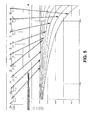
- the configuration of the stages in FIG. 2 is recognizable to those of ordinary skill in the art to be a low pass filter. While the topology is the same as a low pass filter, the values of the components are radically different. The component values are mistuned. That is, the component values are sized to create flat group delay with frequency, which is not done with low pass filters. The component values are also sized to create relatively flat attenuation over a broad frequency range. As shown in FIG. 5 , the first 4 or 5 transfer functions (from the center out) are flat. The group delay along the ladder is cumulative as is seen in FIG. 4 .
- the taps to the ladder network 204 are connected to the drivers 202a-202t such that the shortest delays are provided to the signals coupled to the drivers in the center of the array and the delays increasing to the signals coupled to the drivers extending up and down from the center drivers 202j, 202k.
- the drivers 202a-202t are driven in driver pairs physically positioned symmetrically about the center of the loudspeaker array 202.
- the center drivers 202j, 202k are positioned vertically at the center of the array
- the next driver pair 202i, 2021 are arranged with driver 202i positioned above center driver 202j and driver 2021 positioned below center driver 202k.
- the subsequent driver pairs are arranged similarly from the center to the top and bottom.
- the driver pairs are connected to the ladder network 204 such that the signal is coupled to one terminal (for example, the '+' terminal) of one driver in the pair.
- the other terminal for example, the '-' terminal
- the opposite terminal for example, the '-' terminal
- the opposite terminal for example, the '-' terminal of the other driver in the driver pair is connected to a common connection that connects one terminal of half of the drivers in the array 202. That is, the common connection connects one terminal of the other driver in each driver pair.
- An opposite terminal of the driver pair is connected to the ladder network 204 to receive the delayed signal.
- the center drivers 202j, 202k are connected to the audio signal input V i such that the audio signal coupled to the center driver pair 202j, 202k is not delayed.
- the LC branch formed with inductor L 1 and capacitor C provides the first delay, which is inserted to the signal coupled to the first driver pair 202i, 2021.
- the LC branch formed with inductor L 2 and capacitor C 2 provides the second delay, which is added to the first delay and inserted to the signal coupled to the second driver pair 202h, 202m.
- Each succeeding branch formed by inductors L 3 -L 9 and capacitor C 1 -C 9 provides a progressively greater delay to each succeeding driver pair such that the delay is increasing for the drivers closest to the top and bottom.
- each driver pair (top and bottom) of transducers is tapped off the ladder at further increments in group delay so the outside transducers receive delay from all sections of the ladder thereby receiving the greatest delay.
- the group delay yields an apparent curving of the array in the vertical dimension.
- FIG. 3 is a schematic diagram of several driver pairs connected to corresponding stages formed by the LC branches in the delay network in FIG. 2 .
- FIG. 3 shows the center driver pair 202j, 202k; the next driver pair 202i, 2021 after the center driver pair 202j, 202k; and the next driver pair 202h, 202m after the previous driver pair 202i, 2021.
- the ladder network includes the first stage formed with the LC branch of inductor L 1 and capacitor C 1 ; and the second stage formed with the LC branch of inductor L 2 and capacitor C 2 .
- the succeeding LC branches are not shown for purposes of providing clarity of the description but could continue ad infinitum.
- the ladder network includes an audio input signal generator 302 coupled to the input of the ladder network.
- the first tap in the ladder network connects directly to the first driver pair 202j, 202k.
- the first driver pair 202j, 202k is the center driver pair, which receives the audio signal without delay.
- the second tap in the ladder network between inductor L 1 and inductor L 2 is connected to the second driver pair 202i, 2021.
- the first driver 202i in the second driver pair receives the delay and signal attenuation provided by the first LC branch formed by inductor L 1 and C 1 .
- the first delay is inserted to the signal coupled to the first driver on top of the center driver 202j, which is driver 202i; and to the first driver below the center driver 202k, which is driver 2021.
- the third tap in the ladder network between inductor L 2 and inductor L 3 is connected to the third driver pair 202h, 202m.
- the first driver 202h in the third driver pair receives the delay and signal attenuation provided by both the first LC branch formed by inductor L 1 and C 1 and the second LC branch formed by inductor L 2 and C 2 ,
- the second delay is inserted to the signal coupled to the second driver on top of the center driver 202j, which is driver 202h; and to the second driver below the center driver 202k, which is driver 202i.
- the signal is progressively attenuated.
- the signal received by the drivers at the ends is attenuated relative to the signal at the center drivers 202j, 202k.
- the graphs in FIGs. 4 and 5 illustrate the group delay and magnitude attenuation provided by an example ladder network 204. These two effects of the ladder network 204 operate similar to the CBT concept with time delay and amplitude shading creating a constant width coverage beam at frequencies in which the wave length is smaller than the size of the array.
- FIG. 4 is a graph illustrating the group delay versus frequency at each driver pair in the loudspeaker array in FIG. 2 .
- Each curve in the graph represents the delay inserted at the signal at each tap in the ladder network 204 through the frequency range of operation. As shown in FIG. 4 , the delay is increasingly greater at each successive tap starting from the tap at the audio signal input, which is connected to the center drivers 202j, 202k. The delay is longest at the tap after the LC branch formed by inductor L 9 and capacitor C 9 , which connect to the drivers at the top (at 202a) and bottom (at 202t) of the loudspeaker array.
- FIG. 5 is a graph illustrating shading of drivers in the loudspeaker array in FIG. 2 .
- Each curve in the graph in FIG. 5 represents the amplitude at each tap in the ladder network 204 through the frequency range of operation.
- the signal is increasingly attenuated at each successive tap starting from the tap at the audio signal input, which is connected to the center drivers 202j, 202k.
- FIG. 6 is a graph illustrating the beamwidth versus frequency for a group delay derived array versus straight line array.
- the graphs are beamwidth plots for a 16-element array of one meter high.
- the graph for the group delay derived array shows beamwidth for a group delay derived with a broad vertical beam of 40 degrees (above 800 Hz).
- FIG. 7 is a graph illustrating the beamwidth versus frequency for 2 different arrays of 16 elements of the same size, the arrays having delay networks with different component values.
- the graph in FIG. 7 is a beamwidth plot for an 16-element away of one meter high with two different sets of component values to derive a narrow pattern and a wide pattern.
- the graph illustrates the comparison between a coverage of 15 degrees (above 5 kHz) versus 40 degrees (above 800 Hz).
- FIG. 7 shows how the beamwidth may be varied by adjusting the component values of the passive components in the ladder delay network.
- the beamwidth plots of the 16-element array in FIG. 7 are identical below 1kHz. This is because below 1kHz, the coverage is defined by the height of the array, which in this case is one meter.
- FIGs. 6-7 illustrate performance of vertically-oriented arrays.
- the loudspeaker arrays may also be oriented horizontally.
- the term 'beamwidth' refers to a width in the direction of the array configuration.
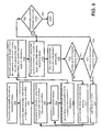
- FIG. 8 is a flowchart depicting operation of an example of a method for providing an arc coverage pattern using a linear loudspeaker array.
- the method illustrated in FIG. 8 may be implemented using a computer program having a user interface that permits user interaction for setting component values, loudspeaker positions, configuring views for data analysis, and setting any other parameter.
- the computer program may be developed as an application using a suitable programming language, or may be implemented as a macro or a sequence of instructions in an application such as a spreadsheet, a database, or suitable alternatives.
- the example method illustrated in FIG. 8 allows a user to determine component values for use in a selected network to create an arc coverage pattern with a linearly arranged loudspeaker array.
- the method also allows the user to optimize performance of the network by ensuring that a constant beam width is achieved at a desired level over the desired frequency range.
- the desired beamwidth and the desired bandwidth are determined.
- the beamwidth and bandwidth specifications may be entered into memory, or may be requested from the user via a user interface query.
- the user interface query may be a menu-driven interface, an electronic form, or any suitable alternative form of data entry.
- the driver spacing is determined.
- the spacing is the distance between the drivers.
- the driver spacing may be provided in memory or requested from the user via a user interface, In general, the driver spacing should be less than one wavelength (A) of the highest frequency being controlled.
- the number of drivers to be used in the linear array is determined.
- driver spacing is determined.
- the number of drivers may be provided in memory or requested from the user via a user interface. In general, the number of drivers should be selected so that the height of the linear array is longer than one wavelength (A) of the lowest frequency being controlled.
- a ladder network is generated.
- the ladder network may be defined by the topology of the stages, the components and component values.
- the configuration of each stage may be pro-defined in memory and offered to the user as alternatives from which to choose.
- a model transfer function is generated for the group delay or the attenuation at each transducer.
- the group delay or attenuation is generated as a function of frequency.
- the transfer function may be generated as a graph, but may be any user readable output. An example of a generated transfer function is shown at Fig. 4 .
- an acoustical model illustrating how the transducers will sum in space is generated.
- the model includes the group delay or attenuation, and may be displayed as beamwidth vs. the frequency.
- Figs. 6 and 7 depict examples of an acoustical model that may be generated to illustrate the beamwidth.
- the component values of the components in the stages of the ladder network may be adjusted to obtain a constant beamwidth over the desired frequency range.
- the component values may be selected from a broad range of values for each component. The values are selected to provide a near constant beamwidth at the desired frequency range. An initial set of values are selected for optimization by further fine tuning of the values.
- the component values are fine-tuned for the most constant beamwidth. Step 816 performs a local search.
- a computational optimizer may be used in step 816 to fine tune the values until values are found that result in the most constant beamwidth at the target value over the required range. Optimizers have an initial condition (or a seed), and will find the local minima, maxima, or fixed values. The computational optimizer may use the component values found in step 814 as a seed.
- the acoustical model is checked to determine if it controls up to the highest frequency. If it does not ("No" branch), a smaller driver and driver spacing are selected at step 820 and the method goes back to step 806. If control up to the highest frequency is attained ("Yes” branch), the acoustical model is checked to determine if it controls down to the lowest frequency at decision block 822. If it is not ("No” branch), additional drivers are added to the ladder network at step 824. The method then continues to step 808 to generate a new ladder network. If control to the lowest frequency is attained at decision block 822 ("Yes" branch), the beamwidth is checked over the entire range at the target value. If the beamwidth is not constant (“No” branch), new seed component values are selected at step 814. If the beamwidth is constant ("Yes” branch), the design is complete.
- a variable pattern control can be achieved using ganged switches that change the value of the components at the same time.
- the sound pattern may also be made to steer up or down if each half (for example, the top half and the bottom half) is driven with different ladder networks.
- a wider pattern coverage may also be achieved by adding physical curving of the array, so the array is not perfectly straight. The additional curving could be applied to only one half or to both asymmetrically.
- the center drivers received the signal without a delay.
- a ground plane version may be created by providing the ladder delay from one end to the other of the array and positioning the non-delayed end perpendicular to a boundary.
Landscapes
- Physics & Mathematics (AREA)
- Engineering & Computer Science (AREA)
- Acoustics & Sound (AREA)
- Signal Processing (AREA)
- Health & Medical Sciences (AREA)
- Otolaryngology (AREA)
- General Health & Medical Sciences (AREA)
- Circuit For Audible Band Transducer (AREA)
Applications Claiming Priority (2)
| Application Number | Priority Date | Filing Date | Title |
|---|---|---|---|
| US14333609P | 2009-01-08 | 2009-01-08 | |
| US12/684,598 US8971547B2 (en) | 2009-01-08 | 2010-01-08 | Passive group delay beam forming |
Publications (2)
| Publication Number | Publication Date |
|---|---|
| EP2247120A2 true EP2247120A2 (fr) | 2010-11-03 |
| EP2247120A3 EP2247120A3 (fr) | 2013-03-06 |
Family
ID=42760660
Family Applications (1)
| Application Number | Title | Priority Date | Filing Date |
|---|---|---|---|
| EP20100151410 Ceased EP2247120A3 (fr) | 2009-01-08 | 2010-01-22 | Formation de faisceau de retard de groupe passif |
Country Status (2)
| Country | Link |
|---|---|
| US (2) | US8971547B2 (fr) |
| EP (1) | EP2247120A3 (fr) |
Families Citing this family (8)
| Publication number | Priority date | Publication date | Assignee | Title |
|---|---|---|---|---|
| JP5640911B2 (ja) * | 2011-06-30 | 2014-12-17 | ヤマハ株式会社 | スピーカアレイ装置 |
| US20170251296A1 (en) * | 2014-09-19 | 2017-08-31 | Dolby Laboratories Licensing Corporation | Loudspeaker with narrow dispersion |
| US10735859B2 (en) * | 2015-05-22 | 2020-08-04 | Lamassu Llc | Line array speaker with frequency-dependent electrical tapering optimized for midrange and high frequency reproduction in the nearfield |
| US9955260B2 (en) * | 2016-05-25 | 2018-04-24 | Harman International Industries, Incorporated | Asymmetrical passive group delay beamforming |
| US10382112B2 (en) * | 2017-07-14 | 2019-08-13 | Facebook, Inc. | Beamforming using passive time-delay structures |
| EP3429224A1 (fr) | 2017-07-14 | 2019-01-16 | Fraunhofer-Gesellschaft zur Förderung der angewandten Forschung e.V. | Haut-parleur |
| US12525997B2 (en) * | 2020-11-17 | 2026-01-13 | Nokia Technologies Oy | Group delay compensation |
| JP2024546837A (ja) * | 2021-12-15 | 2024-12-26 | アティエヴァ、インコーポレイテッド | 非標準的なスピーカロケーションを有する車両オーディオシステムにおいて標準化されたスタジオでの体験を近似する信号処理 |
Family Cites Families (16)
| Publication number | Priority date | Publication date | Assignee | Title |
|---|---|---|---|---|
| US1643323A (en) | 1921-01-04 | 1927-09-27 | American Telephone & Telegraph | Directive antenna array |
| US3068431A (en) * | 1959-01-02 | 1962-12-11 | Alford Andrew | Variable delay line |
| US3125181A (en) | 1961-06-21 | 1964-03-17 | pawlowski | |
| US3299206A (en) | 1963-07-24 | 1967-01-17 | Bolt Beranek & Newman | Line-source loudspeakers |
| JPS5639757B2 (fr) * | 1975-03-03 | 1981-09-16 | ||
| US4330691A (en) * | 1980-01-31 | 1982-05-18 | The Futures Group, Inc. | Integral ceiling tile-loudspeaker system |
| JPS57192195A (en) | 1981-05-15 | 1982-11-26 | Beard Terry D | Electric-acoustic transducer |
| US4845759A (en) | 1986-04-25 | 1989-07-04 | Intersonics Incorporated | Sound source having a plurality of drivers operating from a virtual point |
| JPH0541897A (ja) | 1991-08-07 | 1993-02-19 | Pioneer Electron Corp | スピーカ装置およびその指向性制御方法 |
| NL9401860A (nl) | 1994-11-08 | 1996-06-03 | Duran Bv | Luidsprekersysteem met bestuurde richtinggevoeligheid. |
| DE19739425A1 (de) * | 1997-09-09 | 1999-03-11 | Bosch Gmbh Robert | Verfahren und Anordnung zur Wiedergabe eines sterophonen Audiosignals |
| US7092675B2 (en) * | 1998-05-29 | 2006-08-15 | Silicon Laboratories | Apparatus and methods for generating radio frequencies in communication circuitry using multiple control signals |
| US7260235B1 (en) | 2000-10-16 | 2007-08-21 | Bose Corporation | Line electroacoustical transducing |
| US20020131608A1 (en) * | 2001-03-01 | 2002-09-19 | William Lobb | Method and system for providing digitally focused sound |
| US7826622B2 (en) * | 2003-05-27 | 2010-11-02 | Harman International Industries, Incorporated | Constant-beamwidth loudspeaker array |
| WO2008115284A2 (fr) | 2006-10-16 | 2008-09-25 | Thx Ltd. | Configurations d'agencement en ligne de haut-parleurs, et traitement de son s'y rapportant |
-
2010
- 2010-01-08 US US12/684,598 patent/US8971547B2/en active Active
- 2010-01-22 EP EP20100151410 patent/EP2247120A3/fr not_active Ceased
-
2015
- 2015-01-16 US US14/599,266 patent/US9426562B2/en active Active
Non-Patent Citations (1)
| Title |
|---|
| "Delay Lines", CATALOGS, DATASHEETS & APPLICATION NOTES, 1 January 2001 (2001-01-01), XP055150187, Retrieved from the Internet <URL:http://www.rhombus-ind.com/cats/dl2001.pdf> [retrieved on 20141031] * |
Also Published As
| Publication number | Publication date |
|---|---|
| US9426562B2 (en) | 2016-08-23 |
| US8971547B2 (en) | 2015-03-03 |
| EP2247120A3 (fr) | 2013-03-06 |
| US20130336505A1 (en) | 2013-12-19 |
| US20150139455A1 (en) | 2015-05-21 |
Similar Documents
| Publication | Publication Date | Title |
|---|---|---|
| US9426562B2 (en) | Passive group delay beam forming | |
| US9113257B2 (en) | Phase-unified loudspeakers: parallel crossovers | |
| US8218789B2 (en) | Phase equalization for multi-channel loudspeaker-room responses | |
| EP3466112B1 (fr) | Formation de faisceau de retard de groupe passif asymétrique | |
| US20120283999A1 (en) | Loudspeaker array system | |
| US20150312693A1 (en) | Phase-unified loudspeakers: series crossovers | |
| JP2003506984A (ja) | 音再生のための補償システムおよび補償方法 | |
| Self | The Design of Active Crossovers | |
| US3457370A (en) | Impedance correcting networks | |
| US11856359B2 (en) | Loudspeaker polar pattern creation procedure | |
| JP3230525B2 (ja) | ツーウエイ・スピーカ・システム用修正回路及び方法 | |
| US7085389B1 (en) | Infinite slope loudspeaker crossover filter | |
| US20080044038A1 (en) | Stereophonic sound system | |
| CN110915230B (zh) | 恒定方向性双向楔形扬声器系统 | |
| US6707919B2 (en) | Driver control circuit | |
| US9154878B2 (en) | Interconnected speaker system | |
| RU2799663C1 (ru) | Фильтр для многополосной акустической системы | |
| JP7791740B2 (ja) | スピーカ装置及び音響システム | |
| CN112135225B (zh) | 扬声器系统和电子设备 | |
| Fincham | Multiple-driver loudspeaker systems | |
| EP4655952A1 (fr) | Procédé de traitement de signal audio de réseau de haut-parleurs | |
| Bharitkar et al. | Optimization of crossover frequency and crossover region response for multichannel acoustic applications | |
| HK40025434A (en) | Constant-directivity two way wedge loudspeaker system | |
| HK40025434B (en) | Constant-directivity two way wedge loudspeaker system | |
| KR20060127108A (ko) | 1차 스피커 크로스오버 네트워크 |
Legal Events
| Date | Code | Title | Description |
|---|---|---|---|
| PUAI | Public reference made under article 153(3) epc to a published international application that has entered the european phase |
Free format text: ORIGINAL CODE: 0009012 |
|
| AK | Designated contracting states |
Kind code of ref document: A2 Designated state(s): AT BE BG CH CY CZ DE DK EE ES FI FR GB GR HR HU IE IS IT LI LT LU LV MC MK MT NL NO PL PT RO SE SI SK SM TR |
|
| AX | Request for extension of the european patent |
Extension state: AL BA RS |
|
| PUAL | Search report despatched |
Free format text: ORIGINAL CODE: 0009013 |
|
| AK | Designated contracting states |
Kind code of ref document: A3 Designated state(s): AT BE BG CH CY CZ DE DK EE ES FI FR GB GR HR HU IE IS IT LI LT LU LV MC MK MT NL NO PL PT RO SE SI SK SM TR |
|
| AX | Request for extension of the european patent |
Extension state: AL BA RS |
|
| 17P | Request for examination filed |
Effective date: 20130829 |
|
| RBV | Designated contracting states (corrected) |
Designated state(s): AT BE BG CH CY CZ DE DK EE ES FI FR GB GR HR HU IE IS IT LI LT LU LV MC MK MT NL NO PL PT RO SE SI SK SM TR |
|
| 17Q | First examination report despatched |
Effective date: 20131112 |
|
| R17C | First examination report despatched (corrected) |
Effective date: 20131112 |
|
| APBK | Appeal reference recorded |
Free format text: ORIGINAL CODE: EPIDOSNREFNE |
|
| APBN | Date of receipt of notice of appeal recorded |
Free format text: ORIGINAL CODE: EPIDOSNNOA2E |
|
| APBR | Date of receipt of statement of grounds of appeal recorded |
Free format text: ORIGINAL CODE: EPIDOSNNOA3E |
|
| APAV | Appeal reference deleted |
Free format text: ORIGINAL CODE: EPIDOSDREFNE |
|
| APBX | Invitation to file observations in appeal sent |
Free format text: ORIGINAL CODE: EPIDOSNOBA2E |
|
| APBZ | Receipt of observations in appeal recorded |
Free format text: ORIGINAL CODE: EPIDOSNOBA4E |
|
| APBT | Appeal procedure closed |
Free format text: ORIGINAL CODE: EPIDOSNNOA9E |
|
| STAA | Information on the status of an ep patent application or granted ep patent |
Free format text: STATUS: THE APPLICATION HAS BEEN REFUSED |
|
| 18R | Application refused |
Effective date: 20170407 |