EP2247186B1 - Procédé et dispositif de mélange et/ou de pétrissage de produits alimentaires - Google Patents
Procédé et dispositif de mélange et/ou de pétrissage de produits alimentaires Download PDFInfo
- Publication number
- EP2247186B1 EP2247186B1 EP09705697.2A EP09705697A EP2247186B1 EP 2247186 B1 EP2247186 B1 EP 2247186B1 EP 09705697 A EP09705697 A EP 09705697A EP 2247186 B1 EP2247186 B1 EP 2247186B1
- Authority
- EP
- European Patent Office
- Prior art keywords
- container
- outlet
- food products
- shaft
- inlet
- Prior art date
- Legal status (The legal status is an assumption and is not a legal conclusion. Google has not performed a legal analysis and makes no representation as to the accuracy of the status listed.)
- Not-in-force
Links
- 235000013305 food Nutrition 0.000 title claims description 89
- 238000000034 method Methods 0.000 title claims description 51
- 238000004898 kneading Methods 0.000 title claims description 25
- 239000000203 mixture Substances 0.000 claims description 8
- 125000006850 spacer group Chemical group 0.000 claims description 5
- 238000011144 upstream manufacturing Methods 0.000 claims description 2
- 238000007790 scraping Methods 0.000 claims 3
- 230000005484 gravity Effects 0.000 description 7
- 238000001514 detection method Methods 0.000 description 6
- 239000007789 gas Substances 0.000 description 4
- 230000000694 effects Effects 0.000 description 3
- 238000010008 shearing Methods 0.000 description 3
- 238000011282 treatment Methods 0.000 description 3
- 238000012423 maintenance Methods 0.000 description 2
- 235000014594 pastries Nutrition 0.000 description 2
- 230000002035 prolonged effect Effects 0.000 description 2
- 238000004804 winding Methods 0.000 description 2
- 208000010392 Bone Fractures Diseases 0.000 description 1
- 206010017076 Fracture Diseases 0.000 description 1
- 230000003190 augmentative effect Effects 0.000 description 1
- 230000006835 compression Effects 0.000 description 1
- 238000007906 compression Methods 0.000 description 1
- 230000001143 conditioned effect Effects 0.000 description 1
- 230000003750 conditioning effect Effects 0.000 description 1
- 230000003247 decreasing effect Effects 0.000 description 1
- 238000007599 discharging Methods 0.000 description 1
- 235000013312 flour Nutrition 0.000 description 1
- 235000013373 food additive Nutrition 0.000 description 1
- 239000002778 food additive Substances 0.000 description 1
- 235000012041 food component Nutrition 0.000 description 1
- 239000005428 food component Substances 0.000 description 1
- 239000004615 ingredient Substances 0.000 description 1
- 239000007788 liquid Substances 0.000 description 1
- 235000011837 pasties Nutrition 0.000 description 1
- 230000000737 periodic effect Effects 0.000 description 1
- 235000019699 ravioli Nutrition 0.000 description 1
- 238000009877 rendering Methods 0.000 description 1
- 230000002441 reversible effect Effects 0.000 description 1
Images

Classifications
-
- A—HUMAN NECESSITIES
- A21—BAKING; EDIBLE DOUGHS
- A21C—MACHINES OR EQUIPMENT FOR MAKING OR PROCESSING DOUGHS; HANDLING BAKED ARTICLES MADE FROM DOUGH
- A21C1/00—Mixing or kneading machines for the preparation of dough
- A21C1/06—Mixing or kneading machines for the preparation of dough with horizontally-mounted mixing or kneading tools; Worm or screw mixers
-
- A—HUMAN NECESSITIES
- A21—BAKING; EDIBLE DOUGHS
- A21C—MACHINES OR EQUIPMENT FOR MAKING OR PROCESSING DOUGHS; HANDLING BAKED ARTICLES MADE FROM DOUGH
- A21C1/00—Mixing or kneading machines for the preparation of dough
- A21C1/14—Structural elements of mixing or kneading machines; Parts; Accessories
- A21C1/142—Feeding mechanisms, e.g. skip lifting mechanisms
-
- A—HUMAN NECESSITIES
- A21—BAKING; EDIBLE DOUGHS
- A21C—MACHINES OR EQUIPMENT FOR MAKING OR PROCESSING DOUGHS; HANDLING BAKED ARTICLES MADE FROM DOUGH
- A21C1/00—Mixing or kneading machines for the preparation of dough
- A21C1/14—Structural elements of mixing or kneading machines; Parts; Accessories
- A21C1/144—Discharge mechanisms
-
- A—HUMAN NECESSITIES
- A21—BAKING; EDIBLE DOUGHS
- A21C—MACHINES OR EQUIPMENT FOR MAKING OR PROCESSING DOUGHS; HANDLING BAKED ARTICLES MADE FROM DOUGH
- A21C1/00—Mixing or kneading machines for the preparation of dough
- A21C1/14—Structural elements of mixing or kneading machines; Parts; Accessories
- A21C1/145—Controlling; Testing; Measuring
- A21C1/146—Measuring properties of the dough, e.g. moisture, electrical conductivity, temperature
-
- A—HUMAN NECESSITIES
- A21—BAKING; EDIBLE DOUGHS
- A21C—MACHINES OR EQUIPMENT FOR MAKING OR PROCESSING DOUGHS; HANDLING BAKED ARTICLES MADE FROM DOUGH
- A21C3/00—Machines or apparatus for shaping batches of dough before subdivision
- A21C3/04—Dough-extruding machines ; Hoppers with moving elements, e.g. rollers or belts as wall elements for drawing the dough
-
- B—PERFORMING OPERATIONS; TRANSPORTING
- B01—PHYSICAL OR CHEMICAL PROCESSES OR APPARATUS IN GENERAL
- B01F—MIXING, e.g. DISSOLVING, EMULSIFYING OR DISPERSING
- B01F27/00—Mixers with rotary stirring devices in fixed receptacles; Kneaders
- B01F27/05—Stirrers
- B01F27/07—Stirrers characterised by their mounting on the shaft
- B01F27/072—Stirrers characterised by their mounting on the shaft characterised by the disposition of the stirrers with respect to the rotating axis
- B01F27/0721—Stirrers characterised by their mounting on the shaft characterised by the disposition of the stirrers with respect to the rotating axis parallel with respect to the rotating axis
-
- B—PERFORMING OPERATIONS; TRANSPORTING
- B01—PHYSICAL OR CHEMICAL PROCESSES OR APPARATUS IN GENERAL
- B01F—MIXING, e.g. DISSOLVING, EMULSIFYING OR DISPERSING
- B01F27/00—Mixers with rotary stirring devices in fixed receptacles; Kneaders
- B01F27/05—Stirrers
- B01F27/07—Stirrers characterised by their mounting on the shaft
- B01F27/072—Stirrers characterised by their mounting on the shaft characterised by the disposition of the stirrers with respect to the rotating axis
- B01F27/0727—Stirrers characterised by their mounting on the shaft characterised by the disposition of the stirrers with respect to the rotating axis having stirring elements connected to the stirrer shaft each by two or more radial rods, e.g. the shaft being interrupted between the rods, or of crankshaft type
-
- B—PERFORMING OPERATIONS; TRANSPORTING
- B01—PHYSICAL OR CHEMICAL PROCESSES OR APPARATUS IN GENERAL
- B01F—MIXING, e.g. DISSOLVING, EMULSIFYING OR DISPERSING
- B01F27/00—Mixers with rotary stirring devices in fixed receptacles; Kneaders
- B01F27/50—Pipe mixers, i.e. mixers wherein the materials to be mixed flow continuously through pipes, e.g. column mixers
-
- B—PERFORMING OPERATIONS; TRANSPORTING
- B01—PHYSICAL OR CHEMICAL PROCESSES OR APPARATUS IN GENERAL
- B01F—MIXING, e.g. DISSOLVING, EMULSIFYING OR DISPERSING
- B01F27/00—Mixers with rotary stirring devices in fixed receptacles; Kneaders
- B01F27/60—Mixers with rotary stirring devices in fixed receptacles; Kneaders with stirrers rotating about a horizontal or inclined axis
- B01F27/70—Mixers with rotary stirring devices in fixed receptacles; Kneaders with stirrers rotating about a horizontal or inclined axis with paddles, blades or arms
- B01F27/701—Mixers with rotary stirring devices in fixed receptacles; Kneaders with stirrers rotating about a horizontal or inclined axis with paddles, blades or arms comprising two or more shafts, e.g. in consecutive mixing chambers
- B01F27/702—Mixers with rotary stirring devices in fixed receptacles; Kneaders with stirrers rotating about a horizontal or inclined axis with paddles, blades or arms comprising two or more shafts, e.g. in consecutive mixing chambers with intermeshing paddles
-
- B—PERFORMING OPERATIONS; TRANSPORTING
- B01—PHYSICAL OR CHEMICAL PROCESSES OR APPARATUS IN GENERAL
- B01F—MIXING, e.g. DISSOLVING, EMULSIFYING OR DISPERSING
- B01F35/00—Accessories for mixers; Auxiliary operations or auxiliary devices; Parts or details of general application
- B01F35/10—Maintenance of mixers
- B01F35/12—Maintenance of mixers using mechanical means
- B01F35/123—Maintenance of mixers using mechanical means using scrapers for cleaning mixers
-
- B—PERFORMING OPERATIONS; TRANSPORTING
- B01—PHYSICAL OR CHEMICAL PROCESSES OR APPARATUS IN GENERAL
- B01F—MIXING, e.g. DISSOLVING, EMULSIFYING OR DISPERSING
- B01F35/00—Accessories for mixers; Auxiliary operations or auxiliary devices; Parts or details of general application
- B01F35/20—Measuring; Control or regulation
- B01F35/21—Measuring
- B01F35/213—Measuring of the properties of the mixtures, e.g. temperature, density or colour
-
- B—PERFORMING OPERATIONS; TRANSPORTING
- B01—PHYSICAL OR CHEMICAL PROCESSES OR APPARATUS IN GENERAL
- B01F—MIXING, e.g. DISSOLVING, EMULSIFYING OR DISPERSING
- B01F35/00—Accessories for mixers; Auxiliary operations or auxiliary devices; Parts or details of general application
- B01F35/20—Measuring; Control or regulation
- B01F35/22—Control or regulation
- B01F35/221—Control or regulation of operational parameters, e.g. level of material in the mixer, temperature or pressure
- B01F35/2211—Amount of delivered fluid during a period
-
- B—PERFORMING OPERATIONS; TRANSPORTING
- B01—PHYSICAL OR CHEMICAL PROCESSES OR APPARATUS IN GENERAL
- B01F—MIXING, e.g. DISSOLVING, EMULSIFYING OR DISPERSING
- B01F35/00—Accessories for mixers; Auxiliary operations or auxiliary devices; Parts or details of general application
- B01F35/20—Measuring; Control or regulation
- B01F35/22—Control or regulation
- B01F35/221—Control or regulation of operational parameters, e.g. level of material in the mixer, temperature or pressure
- B01F35/2214—Speed during the operation
- B01F35/22142—Speed of the mixing device during the operation
-
- B—PERFORMING OPERATIONS; TRANSPORTING
- B01—PHYSICAL OR CHEMICAL PROCESSES OR APPARATUS IN GENERAL
- B01F—MIXING, e.g. DISSOLVING, EMULSIFYING OR DISPERSING
- B01F35/00—Accessories for mixers; Auxiliary operations or auxiliary devices; Parts or details of general application
- B01F35/20—Measuring; Control or regulation
- B01F35/22—Control or regulation
- B01F35/221—Control or regulation of operational parameters, e.g. level of material in the mixer, temperature or pressure
- B01F35/2215—Temperature
-
- B—PERFORMING OPERATIONS; TRANSPORTING
- B01—PHYSICAL OR CHEMICAL PROCESSES OR APPARATUS IN GENERAL
- B01F—MIXING, e.g. DISSOLVING, EMULSIFYING OR DISPERSING
- B01F35/00—Accessories for mixers; Auxiliary operations or auxiliary devices; Parts or details of general application
- B01F35/20—Measuring; Control or regulation
- B01F35/22—Control or regulation
- B01F35/221—Control or regulation of operational parameters, e.g. level of material in the mixer, temperature or pressure
- B01F35/2216—Time, i.e. duration, of at least one parameter during the operation
- B01F35/22161—Time, i.e. duration, of at least one parameter during the operation duration of the mixing process or parts of it
-
- B—PERFORMING OPERATIONS; TRANSPORTING
- B01—PHYSICAL OR CHEMICAL PROCESSES OR APPARATUS IN GENERAL
- B01F—MIXING, e.g. DISSOLVING, EMULSIFYING OR DISPERSING
- B01F35/00—Accessories for mixers; Auxiliary operations or auxiliary devices; Parts or details of general application
- B01F35/71—Feed mechanisms
- B01F35/717—Feed mechanisms characterised by the means for feeding the components to the mixer
- B01F35/7173—Feed mechanisms characterised by the means for feeding the components to the mixer using gravity, e.g. from a hopper
-
- B—PERFORMING OPERATIONS; TRANSPORTING
- B01—PHYSICAL OR CHEMICAL PROCESSES OR APPARATUS IN GENERAL
- B01F—MIXING, e.g. DISSOLVING, EMULSIFYING OR DISPERSING
- B01F35/00—Accessories for mixers; Auxiliary operations or auxiliary devices; Parts or details of general application
- B01F35/71—Feed mechanisms
- B01F35/717—Feed mechanisms characterised by the means for feeding the components to the mixer
- B01F35/7177—Feed mechanisms characterised by the means for feeding the components to the mixer using rollers
-
- B—PERFORMING OPERATIONS; TRANSPORTING
- B01—PHYSICAL OR CHEMICAL PROCESSES OR APPARATUS IN GENERAL
- B01F—MIXING, e.g. DISSOLVING, EMULSIFYING OR DISPERSING
- B01F35/00—Accessories for mixers; Auxiliary operations or auxiliary devices; Parts or details of general application
- B01F35/71—Feed mechanisms
- B01F35/717—Feed mechanisms characterised by the means for feeding the components to the mixer
- B01F35/71805—Feed mechanisms characterised by the means for feeding the components to the mixer using valves, gates, orifices or openings
- B01F35/718051—Feed mechanisms characterised by the means for feeding the components to the mixer using valves, gates, orifices or openings being adjustable
-
- B—PERFORMING OPERATIONS; TRANSPORTING
- B01—PHYSICAL OR CHEMICAL PROCESSES OR APPARATUS IN GENERAL
- B01F—MIXING, e.g. DISSOLVING, EMULSIFYING OR DISPERSING
- B01F35/00—Accessories for mixers; Auxiliary operations or auxiliary devices; Parts or details of general application
- B01F35/75—Discharge mechanisms
-
- B—PERFORMING OPERATIONS; TRANSPORTING
- B01—PHYSICAL OR CHEMICAL PROCESSES OR APPARATUS IN GENERAL
- B01F—MIXING, e.g. DISSOLVING, EMULSIFYING OR DISPERSING
- B01F35/00—Accessories for mixers; Auxiliary operations or auxiliary devices; Parts or details of general application
- B01F35/75—Discharge mechanisms
- B01F35/754—Discharge mechanisms characterised by the means for discharging the components from the mixer
- B01F35/75415—Discharge mechanisms characterised by the means for discharging the components from the mixer using gravity
-
- B—PERFORMING OPERATIONS; TRANSPORTING
- B01—PHYSICAL OR CHEMICAL PROCESSES OR APPARATUS IN GENERAL
- B01F—MIXING, e.g. DISSOLVING, EMULSIFYING OR DISPERSING
- B01F35/00—Accessories for mixers; Auxiliary operations or auxiliary devices; Parts or details of general application
- B01F35/75—Discharge mechanisms
- B01F35/754—Discharge mechanisms characterised by the means for discharging the components from the mixer
- B01F35/7547—Discharge mechanisms characterised by the means for discharging the components from the mixer using valves, gates, orifices or openings
- B01F35/75471—Discharge mechanisms characterised by the means for discharging the components from the mixer using valves, gates, orifices or openings being adjustable
-
- B—PERFORMING OPERATIONS; TRANSPORTING
- B01—PHYSICAL OR CHEMICAL PROCESSES OR APPARATUS IN GENERAL
- B01F—MIXING, e.g. DISSOLVING, EMULSIFYING OR DISPERSING
- B01F35/00—Accessories for mixers; Auxiliary operations or auxiliary devices; Parts or details of general application
- B01F35/10—Maintenance of mixers
- B01F35/145—Washing or cleaning mixers not provided for in other groups in this subclass; Inhibiting build-up of material on machine parts using other means
Definitions
- the invention relates to a method for mixing and/or kneading food products, using a device which is provided with at least one container having an inlet, an outlet as well as at least one rotary shaft extending substantially in the longitudinal direction of the container, which shaft is provided with at least one tool, which tool comprises at least one bar which is connected to the shaft via spacers, said shaft comprising an operative area for continuous mixing and/or kneading of food products, which extends in the longitudinal direction of said shaft.
- the device comprises a container, in which two counter-rotating shafts are disposed side by side, which shafts are fitted with tools in the form of bars that helically surround the shafts.
- the dough is transported from the inlet to the outlet in use, in the container, the rate of movement of the products in the container being determined by the shape of the tool and the tilting of the container, among other things, so that the force of gravity can contribute positively towards increasing the rate of movement of the food products in the container.
- US-3.752.448 which discloses the preamble of claim 1, and US-3.738.617 both disclose a dough conditioning apparatus.
- Document FR 1.445.076 A1 discloses a device for mixing and/or kneading food products, having adjustable rollers positioned below a kneader, for providing a sheet of pastry at an outlet. The gap between the rollers is adjustable for setting the thickness of the sheet pasty.
- the object of the present invention is to provide an improved method for mixing and/or kneading food products.
- the method it is possible to control the quality of the mixing and/or kneading process of the food products in a container, for example by having the shafts rotate at a higher or lower speed, without this necessarily having any effect on the amount produced by means of the device.
- the rate of movement of the food products between the inlet and the outlet is hardly influenced by the shafts fitted with the tool, because the movement of the food products in the container will according to the invention take place mainly in vertical direction and hardly in horizontal direction.
- the rate of the vertical movement between the inlet and the outlet is mainly determined by gravity.
- the inlet opening extending in the longitudinal direction evenly distributes the food products from, for example, a distributor hopper over the operative area of the tool that extends substantially identically in the longitudinal direction. In this way the entire capacity of the tool extending in longitudinal direction is utilised in an efficient manner and all the food products being supplied are mixed or kneaded in the operative area of the shaft. The food products are discharged from the container through the outlet in the same efficient manner.
- the device used in the method according to the present invention can furthermore be used in a very flexible manner for mixing and/or kneading, in short succession, products that require different mixing and/or kneading treatments.
- a special preferred embodiment of the invention is characterised in that a virtual vertical extends both through the inlet and through the outlet.
- a tool in the form of at least one bar Disposed on a shaft between the inlet and the outlet is a tool in the form of at least one bar, which tool is suitable in particular for kneading food products, the term "kneading” being understood to mean the putting of energy and gas into the food products to be processed, inter alia by means of shearing forces being generated by means of the bars of the tools, but also between the bars and the walls of the container.
- the bar preferably extends over practically the entire length of the shaft, so that the forces will be evenly distributed over the shaft.
- several bars are arranged in line behind each other, or U-shaped brackets are mounted to the shaft, in which case the bridge portion of the U-shaped brackets forms the bar and the legs thereof form the spacers.
- the device used in the method according to the present invention is suitable in particular for kneading a viscous mixture by means of the tool, whilst the rotating bars can also mix the food products present in the container, of course.
- the central axis of the inlet is located substantially on the same vertical as the central axis of the outlet.
- food products as used herein is further understood to refer to food components and additives that are common in the food industry.
- the transverse dimension of the inlet and/or the outlet can be variably adjusted.
- Varying the dimension of the inlet and/or the outlet makes it possible to control the amount per unit time that is supplied to the container and/or the amount per unit time that is discharged from the container, and thus the residence time and the volume of the food products in the container. If it is empirically determined that the food products need to be mixed and/or kneaded longer to obtain the desired quality, the dimension of, for example, the outlet can be temporarily reduced in comparison to the inlet, so that temporarily more food products will be supplied to the container through the inlet than discharged through the outlet in that case. In this way the container will become fuller and the food products will have a longer average stay in the container, such that the food products will be mixed and/or kneaded longer.
- the outlet may be enlarged temporarily in comparison with the inlet.
- Such an inlet and/or outlet whose dimension can be temporarily varied is especially advantageous in the method for continuous mixing and/or kneading of food products according to the invention, because a temporary change of said dimensions makes it possible to control the residence time of the food products and thus the quality of the kneaded and/or mixed food products.
- the dimension of the inlet and the outlet in the longitudinal direction is preferably constant, whilst the width of the inlet and outlet openings is varied, so that it is ensured at the inlet that the food products will be evenly distributed over the tools extending in the longitudinal direction and that uniformly mixed/kneaded food products can be discharged at the outlet.
- the amount of the food products to be treated that is supplied to the container per unit time will preferably be substantially the same as or exhibit a fixed proportion in relation to the amount to be discharged per unit time, so that the container can be operated continuously, thereby providing a device for continuous mixing and/for kneading of food products.
- outlet of the container is provided with two counter-rotatable discharge rollers extending parallel to the shafts, between which a discharge gap is present.
- the food products that have been treated in the container are uniformly discharged from the container by means of such discharge rollers.
- the discharge rate of the treated food products through the outlet can be controlled in dependence on the speed of rotation of the discharge rollers.
- the gases contained in the food products which partially determine the quality of the food products to be treated with the tool, are uniformly distributed by the discharge rollers.
- the food products are additionally stretched by the counter-rotating discharge rollers, which is normally a separate operation, thereby rendering the device used in the method according to the present invention more efficient and thus more economical.
- the discharge rollers are counter-rotating, with the discharge roller located to the right of the discharge gap rotating in anti-clockwise direction and the discharge roller located to the left of the discharge rotating in clockwise direction.
- the invention may also have only one rotatable discharge roller extending parallel to the shaft, in which case a discharge gap will be present between a wall of the container and said discharge roller.
- Yet another embodiment of the device used in the invention is characterised in that the discharge gap is variably adjustable by moving the discharge rollers with respect to each other or by moving the discharge roller with respect to the wall.
- the speed of rotation it is possible to adjust the amount to be discharged per unit time, and thus the residence time of the food products in the container, by varying the outlet opening formed by the discharge gap by means of the variably adjustable discharge gap.
- the gap width of the discharge gap can for example be varied by moving the centres or axes of the discharge rollers relative to each other.
- Another embodiment of the device used in the method according to the invention is characterised in that the inlet of the container is provided with two counter-rotatable supply rollers extending parallel to the shafts, between which a supply gap is present.
- the container inlet is fitted with supply rollers, which evenly distribute the food products to be treated in the longitudinal direction of the tool. It is also possible to set the supply rate of the food products into the container to a desired supply rate in a simple manner by controlling the speed of rotation of the supply rollers. Furthermore, a first mixing and/or kneading treatment takes place by means of a compressive force being exerted on the food products by means of the supply rollers, wherein also the gases contained in the food products can be distributed more uniformly.
- the supply rollers are counter-rotatable, preferably in a similar manner as the discharge rollers.
- a supply rate which can be varied by means of the supply rollers and/or a discharge rate which can be varied by means of the discharge rollers is (are) in particular advantageous in the case of a device for continuous mixing and/or kneading of food products, because it is possible to control the residence time of the food products in the container via a temporary change in said rates, thereby making it possible to control the quality of the kneaded and/or a mixed food products.
- the device comprises only one rotatable supply roller extending parallel to the shaft, in which case a supply gap will be present between the supply roller and a wall of the container.
- Yet another embodiment of the device used in the method according to the invention is characterised in that the supply gap is variably adjustable by moving the supply rollers with respect to each other or by moving the supply roller with respect to the wall.
- the dimension of the inlet opening for the food products formed by the supply gap can be varied by means of the supply roller(s), thus making it possible to set a desired amount to be supplied per unit time.
- the gap with of the discharge gap can be varied by moving the centres or axes of the rollers relative to each other.
- the device used in the method according to the present invention it is also possible to keep the dimension of the supply gap constant and to vary the discharge gap (temporarily), or vice versa. In this way it is possible to control the residence time of the food products, and thus the quality of the food products, in a simple manner while using a relatively simple device, in which only the width of the supply gap or of the discharge gap can be varied.
- Yet another embodiment of the device used in the method according to the invention is characterised in that the tool extends substantially parallel to the shaft.
- the forces that are exerted on the tool in use will be substantially constant if the food products are uniformly distributed over the shaft.
- the risk of fracture is zero, so that the tool will have a relatively long life.
- the spacing between the container wall and the bar or bars of the tool is preferably comparatively small, preferably smaller than half the length of a spacer, so that the shearing forces being generated between the wall and the bar in use will be maximised, resulting in a better kneading result of the food products in the container.
- Yet another embodiment of the device used in the method according to the invention is characterised in that the shaft is provided with at least two tools disposed opposite each other, which tools and which shaft extending therebetween lie in a virtual plane.
- each shaft is provided minimally with two tools. If the two tools and the shaft extending therebetween lie in a virtual plane, the shaft will be loaded symmetrically, resulting in less wear and a prolonged shaft life.
- Yet another embodiment of the device used in the method according to the invention is characterised in that the condition of the food products can be registered by using detection means, which detection means are connected to a control unit, by means of which the amount of energy to be input into the food products can be changed.
- Said detection means may for example be temperature sensors or sensors that measure the energy supplied to the shafts or sensors that measure the viscosity or other quality characteristics of the food products which have been kneaded or mixed and/or are to be kneaded and/or mixed.
- a control unit may respond thereto by changing the energy input into the food products to be kneaded / mixed.
- the amount of energy to be input into the food products can be changed by adjusting the speed of rotation of the shaft(s) and/or the supply rollers and/or the discharge rollers. In this way the shearing forces generated between the tool and the container wall are increased or decreased, so that the food products will be kneaded better or less well.
- the amount of energy to be input into the food products can also be changed by adapting the dimension of the inlet and/or the outlet. In this way the residence time of the food products is influenced, i.e. prolonged or shortened.
- the inlet and/or the outlet are preferably formed by the supply gap and the discharge gap. If the outlet is formed by scrapers, the dimension of the outlet can also be varied by means of said scrapers.
- the amount of energy to be input into the food products can be changed by adjusting the temperature of the supply rollers and/or the discharge rollers and/or the container walls.
- rollers and/or the wall can be heatable.
- the device comprises a pre-mixer for providing a viscous mixture, which pre-mixer is disposed upstream of the container, whilst energy can be added to the viscous mixture in the container by means of the tool.
- a pre-mixer may be a continuous mixer as known per se, which is normally characterised by a spiral or spiral-like tool comprising a large number of windings per unit length, for example more than 10 windings per metre, whilst the food products mixed by means of the pre-mixer are in particular kneaded in the container of the device used in the method according to the present invention.
- Yet another embodiment of the device used in the method according to the invention is characterised in that the shaft or the shafts disposed side by side in the container form a first layer, above which and/or below which there is provided at least one further layer of at least two counter-rotatable shafts extending side by side substantially in the longitudinal direction of the container.
- Discharge rollers and/or supply rollers may be provided between said layers in that case, but preferably all layers are disposed between the discharge rollers and the supply rollers.
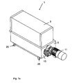
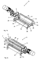
- FIGS 1a-c are perspective views of a device 1 and a container 5 used in the method according to the present invention, from which the outer wall 13 of the container 5 has been left out for the sake of clarity in figures 1b and 1 c.
- the device 1 comprises a pre-mixer 3, which pre-mixer 3 may be a mixer configured in a manner which is known per se, but which preferably has an outlet (not shown) that extends in the longitudinal direction.
- the container 5 of the device 1 used in the method according to the present invention comprises an inlet (not shown), an outlet (not shown), as well as at least two counter-rotatable shafts 7, 9 extending side by side substantially in the longitudinal direction of the container 5.
- the container 5 is provided with a driving mechanism 11.
- the shafts 7, 9 disposed in the container 5 can be rotated in opposite directions by means of the driving mechanism 11. In use, the shafts 7, 9 preferably rotate at a constant rotational speed.
- the container 5 is provided with an inlet for filling the container 5 with the food products to be treated via the outlet of the pre-mixer 3, which is vertically aligned with said inlet, and with an outlet, which is vertically aligned with the inlet, for discharging the treated food products from the container 5.
- the rotary shafts 7, 9 extend the entire length of the container 5.
- the container 5 is further provided with curved walls 16.
- Each shaft 7, 9 is provided with a tool 15, which comprises two bars 17 extending parallel to the shaft 7, 9, which bars are connected to the shaft 7, 9 by means of spacers 19.
- the tool 15 extends in the longitudinal direction and defines an operative area, in which actual contact may take place between the bar 17 of the tool 15 and the food products present in the container 5.
- the food products present in the container 5 are mainly kneaded by means of the bars 17.
- the shafts 7, 9 rotate in opposite directions.
- the tools 15 on the two shafts 7, 9 comprise an overlapping area in the container 5 and are consequently oriented asymmetrically, in mirror image of each other, so that the tool 15 of the first shaft 7 will not come into contact with the tool 15 of the second shaft 9.
- the asymmetrical orientation of the tools 15 is as follows:
- the tools 15 of the shaft 7 lie in a first virtual plane, whilst the two tools 15 of the shaft 9 lie in a second virtual plane, which first virtual plane of the shaft 7 extends transversely to the second virtual plane of the shaft 9.
- a tool 15 which is oriented in such a manner is excellently suitable for kneading the food products. Said kneading process takes place in particular between the longitudinally extending walls 16 of the container 5 and the longitudinally extending bars 17, and also between the bars 17 of the shaft 7 and the bars 17 of the shaft 9.
- the container 5 that is shown in figures 1a-c further comprises an outlet 21, which is bounded by scrapers 23 extending in the longitudinal direction of the container 5, which scrapers are adjustable via slotted holes by means of handles 25.
- the scrapers 23 can be fixed in the desired position by means of the handles 25. In use, the scrapers 23 abut against the curved walls 16. Food products that do not fit in the spaces between the curved walls 16 and the bars 17 while kneading takes place will be discharged via the outlet 21 by means of the scrapers 23.
- the outlet 21 is vertically aligned with the inlet of the container 5, in such a manner that the inlet, which extends substantially in the horizontal plane, is crossed by the same vertical as the outlet 21, which likewise extends substantially in a (lower) horizontal plane.
- the central axis of the inlet is located on the same vertical as the central axis of the outlet 21 of the container 5. Important is that both the outlet and the inlet of the container 5 can extend substantially in the longitudinal direction over the operative area of the shafts, said operative area being formed by the longitudinally extending tool 15.
- the operation of the device 1 is as follows:
- the scrapers 23 do not consume any energy in use and are economical, therefore, as well as low-maintenance.
- Figure 2a is a perspective view of a device 100 used in the method according to the present invention
- figure 2b is a perspective view of the container 105, from which the outer walls of the container 105 have been left out for the sake of clarity.
- the container 105 comprises two shafts 106, 109, which are fitted with a tool 115, which is identical as regards its shape and orientation to the tool 15 that is shown in figures 1b and 1c .
- the container 105 is provided with an inlet 130 ( figure 2a ), which is aligned with the outlet of the pre-mixer 103.
- the container 105 is further provided with an outlet 131, which outlet 131 comprises two counter-rotatable discharge rollers 133, 135 extending parallel to the shafts 107, 109, between which a discharge gap 137 extending in the longitudinal direction of the container 105 is present.
- the width of the discharge gap 137 i.e. the spacing between the discharge rollers 133, 135, is variably adjustable by moving the discharge rollers 133, 135 with respect to each other by means of the adjusting guides 139.
- the discharge rollers 133, 135 have ends 141, which are slidably movable over the adjusting guides 139 and which can be fixed in position thereon, so that a discharge gap 137 having a desired dimension is defined by means of the discharge rollers 133, 135.
- the outlet 131 defined by the discharge gap 137 preferably has the same dimension as the inlet 130, but it is also possible to change said dimension if the conditions in the container require so.
- a virtual vertical extends both through the inlet 130 and through the outlet 131, which means that the inlet 130 and the outlet 131 are vertically aligned.
- the operation of the device 100 is practically identical to the operation of the device 1, with this difference that discharge rollers 133, 135 are provided instead of the scrapers 23.
- the force of gravity has a maximum effect on the transport through the container 105 on account of the vertical that extends both through the inlet 130 and through the outlet 131.
- the discharge rollers 133, 135 provide the additional advantage that the gas present in the kneaded food products is distributed more uniformly.
- the discharge rollers 133, 135 make it possible to obtain a layer of kneaded food products that has a uniform thickness. This is advantageous in connection with the further processing of the kneaded food products.
- the thickness of the kneaded layer of food products can be adjusted by means of the discharge rollers 133, 135.
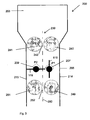
- Figure 3 is a schematic view of another embodiment of the device 200 used in the method according to the present invention.
- the device 200 comprises a pre-mixer 203 and a container 205.
- the inlet 230 of the container 205 is provided with two counter-rotatable supply rollers 240, 241 extending parallel to the shafts 207, 209, between which supply rollers a supply gap 242 is present.
- the supply gap 242 between the supply rollers 240, 241 and also the speed of rotation of the supply rollers is variably adjustable in a similar manner as with the discharge rollers 133, 135.
- the supply roller 240 located to the right of the supply gap 242 rotates in anti-clockwise direction (P1), whilst the supply roller 241 located to the left of the supply gap 242 rotates in clockwise direction (P2).
- the supply rollers comprise a transport function.
- the discharge rollers 249, 251 rotate in the same way as the supply rollers 240, 241.
- the vertical 250 extends both through the supply gap 242 that forms at the inlet of the container 205 and through the discharge 252 that forms the outlet of the container 205.
- the supply gap 242 and the discharge gap 252 are variably adjustable as regards their width dimension by moving the respective supply rollers 240, 241 and discharge rollers 249, 251 relative to each other. Furthermore, the speed of rotation of the supply rollers 240, 241 and the discharge rollers 249, 251 is variably adjustable.
- shafts 207, 209 as shown rotate in an identical manner as the rollers 240, 241, 249, 251, said shafts do not need to comprise a transport function, and they may also rotate in the reverse manner of the illustrated manner of rotation between the walls 214, 215 of the container 205.
- the additional advantage of the supply gap 242 is that the food products from the pre-mixer 203 are evenly distributed over the longitudinally extending tool.
- a first mixing/kneading treatment takes place as a result of the compression between the supply rollers 240, 241.
- the container 5 may additionally be provided with an air supply means (not shown) for supplying conditioned air in, for example, a controlled amount and having a controlled moisture content, composition and temperature.
- an air supply means (not shown) for supplying conditioned air in, for example, a controlled amount and having a controlled moisture content, composition and temperature.
- the device used in the method according to the present invention can be furthermore provided with detection means which are known per se, by means of which the quality of the food products can be directly or indirectly determined, which detection means is connected, via a closed loop, to a control unit by means of which the speed of rotation of the shaft(s) 7, 9, 107, 109, 207, 209 and/or the supply rollers 240, 241 and/or the discharge rollers 133, 135, 249 and 251 can be adjusted, or by means of which the dimension of the supply gap 242 and/or the discharge gap 252 or the space between the scraper 23 can be adjusted or by means of which the temperature of the supply rollers and/or the discharge rollers and/or the container walls can be adjusted.
- the supply rollers and the discharge rollers may be profiled and be heatable or coolable.
- a liquid can be forcibly introduced into the food products by means of said rollers, if desired.
- two rollers defining a gap may have mutually different diameters.
Landscapes
- Chemical & Material Sciences (AREA)
- Chemical Kinetics & Catalysis (AREA)
- Engineering & Computer Science (AREA)
- Life Sciences & Earth Sciences (AREA)
- Food Science & Technology (AREA)
- Mechanical Engineering (AREA)
- Mixers Of The Rotary Stirring Type (AREA)
- Formation And Processing Of Food Products (AREA)
Claims (15)
- Procédé pour mélanger et/ou pétrir continuellement des produits alimentaires en utilisant un dispositif (1 ; 100 ; 200) qui est pourvu d'au moins un récipient (5 ; 105 ; 205) comportant une entrée (130 ; 230), une sortie (21 ; 131) ainsi qu'au moins un arbre rotatif (7, 9 ; 107, 109 ; 207, 209) s'étendant sensiblement dans le sens longitudinal du récipient, lequel arbre est pourvu d'au moins un outil (17 ; 117), lequel outil comprend au moins une barre qui est reliée à l'arbre par l'intermédiaire d'entretoises (19 ; 119 ; 219), ledit arbre comprenant une zone opérationnelle pour mélanger et/ou pétrir continuellement des produits alimentaires, qui s'étend dans le sens longitudinal dudit arbre, dans lequel l'entrée et, également, la sortie s'étendent dans un sens longitudinal sensiblement sur la zone opérationnelle de l'arbre entre l'entrée et la sortie, caractérisé en ce que la dimension transversale de l'entrée et la sortie peut être ajustée variablement et en ce que le procédé comprend l'étape de la variation provisoire de la dimension transversale de l'entrée et la sortie au cours du mélange et/ou du pétrissage pour réguler la quantité par unité de temps qui est fournie au récipient et la quantité par unité de temps qui est déchargée du récipient, et ainsi le temps de séjour et le volume des produits alimentaires dans le récipient.
- Procédé selon la revendication 1, caractérisé en ce qu'une verticale virtuelle s'étend à travers l'entrée et à travers la sortie.
- Procédé selon l'une quelconque des revendications précédentes, caractérisé en ce que la dimension maximale de la sortie correspond sensiblement à la dimension maximale de l'entrée.
- Procédé selon une ou plusieurs des revendications précédentes, caractérisé en ce que la sortie comprend au moins deux rouleaux de déchargement pouvant tourner dans des sens inverses (133, 135 ; 249, 251) s'étendant parallèlement aux arbres, entre lesquels un espacement de déchargement (137 ; 252) est présent, dans lequel l'espacement de déchargement est ajustable variablement en déplaçant les rouleaux de déchargement l'un par rapport à l'autre.
- Procédé selon la revendication 1, caractérisé en ce que la sortie comprend au moins un rouleau de déchargement pouvant tourner dans un sens inverse, s'étendant parallèlement à l'arbre, dans lequel, entre le rouleau et une paroi du récipient, un espacement de déchargement est présent, dans lequel l'espacement de déchargement est ajustable variablement en déplaçant le rouleau de déchargement par rapport à la paroi.
- Procédé selon une ou plusieurs des revendications précédentes, caractérisé en ce que l'entrée comprend au moins deux rouleaux d'alimentation pouvant tourner dans des sens inverses (240, 251), s'étendant parallèlement aux arbres, entre lesquels un espacement d'alimentation (242) est présent.
- Procédé selon la revendication 6, caractérisé en ce que l'espacement d'alimentation est ajustable variablement en déplaçant les rouleaux d'alimentation l'un par rapport à l'autre.
- Procédé selon une ou plusieurs des revendications précédentes, caractérisé en ce que le dispositif comprend en outre des racloirs (23) pour racler les produits alimentaires de l'outil.
- Procédé selon les revendications 4 et/ou 5, caractérisé en ce que le dispositif comprend en outre des racloirs pour racler les produits alimentaires de l'au moins un rouleau de déchargement.
- Procédé selon les revendications 6 et/ou 7, caractérisé en ce que le dispositif comprend en outre des racloirs pour racler les produits alimentaires de l'au moins un rouleau d'alimentation.
- Procédé selon une ou plusieurs des revendications précédentes, caractérisé en ce que la sortie du récipient s'étend entre deux racloirs (23), dans lequel la dimension transversale de la sortie peut être variée au moyen des racloirs.
- Procédé selon une ou plusieurs des revendications précédentes, caractérisé en ce que l'outil s'étend sensiblement parallèlement à l'arbre.
- Procédé selon une ou plusieurs des revendications précédentes, caractérisé en ce que le dispositif est pourvu d'au moins deux outils disposés à l'opposé l'un de l'autre, lesquels outils et lequel arbre s'étendant entre eux se trouvent dans un plan virtuel.
- Procédé selon une ou plusieurs des revendications précédentes, caractérisé en ce que le dispositif comprend un pré-mélangeur (3 ; 103) pour fournir un mélange visqueux, lequel pré-mélangeur est disposé en amont du récipient, pendant que de l'énergie peut être ajoutée au mélange visqueux dans le récipient au moyen de l'outil.
- Procédé selon une ou plusieurs des revendications précédentes, caractérisé en ce que l'arbre ou les arbres disposés côte à côte dans le récipient constituent une première couche au-dessus de laquelle et/ou au-dessous de laquelle il est fourni au moins une autre couche d'au moins deux arbres pouvant tourner dans des sens inverses, s'étendant côte à côte sensiblement dans le sens longitudinal du récipient.
Applications Claiming Priority (2)
| Application Number | Priority Date | Filing Date | Title |
|---|---|---|---|
| NL1034970A NL1034970C2 (nl) | 2008-01-29 | 2008-01-29 | Inrichting voor het mengen en/of kneden van voedingsmiddelen. |
| PCT/NL2009/000015 WO2009096774A2 (fr) | 2008-01-29 | 2009-01-26 | Dispositif de mélange et/ou de pétrissage de produits alimentaires |
Publications (2)
| Publication Number | Publication Date |
|---|---|
| EP2247186A2 EP2247186A2 (fr) | 2010-11-10 |
| EP2247186B1 true EP2247186B1 (fr) | 2014-09-03 |
Family
ID=39719223
Family Applications (1)
| Application Number | Title | Priority Date | Filing Date |
|---|---|---|---|
| EP09705697.2A Not-in-force EP2247186B1 (fr) | 2008-01-29 | 2009-01-26 | Procédé et dispositif de mélange et/ou de pétrissage de produits alimentaires |
Country Status (4)
| Country | Link |
|---|---|
| US (1) | US20110051544A1 (fr) |
| EP (1) | EP2247186B1 (fr) |
| NL (1) | NL1034970C2 (fr) |
| WO (1) | WO2009096774A2 (fr) |
Families Citing this family (4)
| Publication number | Priority date | Publication date | Assignee | Title |
|---|---|---|---|---|
| JP3868757B2 (ja) * | 2001-04-25 | 2007-01-17 | 株式会社神戸製鋼所 | ゴム系組成物の混練装置および混練方法 |
| JP2013176750A (ja) * | 2012-02-09 | 2013-09-09 | Honda Tekko Kk | 混練機 |
| CN109843069B (zh) * | 2016-09-16 | 2023-01-24 | 哈斯食品设备有限责任公司 | 食品面团挤出机 |
| US20230045894A1 (en) * | 2021-08-13 | 2023-02-16 | Seattle Food Tech, Inc. | Asymmetric fluted infeeds |
Citations (2)
| Publication number | Priority date | Publication date | Assignee | Title |
|---|---|---|---|---|
| FR1445076A (fr) * | 1965-08-09 | 1966-07-08 | Ohg Giacomo Toresani S P A | Machine combinée semi-automatique pour la production de feuilles de pâtes alimentaires |
| US3605641A (en) * | 1969-07-22 | 1971-09-20 | Power Mount Corp | Ravioli making machine |
Family Cites Families (11)
| Publication number | Priority date | Publication date | Assignee | Title |
|---|---|---|---|---|
| US2442471A (en) * | 1943-03-27 | 1948-06-01 | Western States Machine Co | System for handling massecuite |
| US3245361A (en) * | 1962-11-13 | 1966-04-12 | Interstate Bakeries Corp | Cake batter production |
| US3738617A (en) * | 1970-10-23 | 1973-06-12 | A Madonia | Dough conditioning apparatus |
| US3752448A (en) * | 1971-09-15 | 1973-08-14 | A Madonia | Dough conditioning apparatus |
| US4083668A (en) * | 1976-04-28 | 1978-04-11 | Bardwick Iii John | Noodle making machine |
| US5261746A (en) * | 1991-03-28 | 1993-11-16 | Boasso Walter J | Method of transporting and blending slurries with an oscillating paddle system |
| US5783222A (en) * | 1996-10-25 | 1998-07-21 | Somerset Industries, Inc. | Dough molder |
| US6193406B1 (en) * | 1996-12-20 | 2001-02-27 | Andritz-Ahlstrom Oy | Method and apparatus for mixing pulp a suspension with a fluid medium with a freely rotatable mixing rotor |
| DE19743470A1 (de) * | 1997-10-01 | 1999-04-08 | Buehler Ag | Verfahren und Vorrichtung zum Vorkonditionieren des in einem Extruder zu verarbeitenden Produktes und dgl. |
| US20040076704A1 (en) * | 2002-10-09 | 2004-04-22 | Hannaford Christopher S. | Progressing cavity extruder |
| NL1029273C2 (nl) | 2005-06-17 | 2006-12-19 | Sotec Beheer B V | Inrichtingen en werkwijzen voor het mengen en/of kneden van voedingsmiddelen. |
-
2008
- 2008-01-29 NL NL1034970A patent/NL1034970C2/nl not_active IP Right Cessation
-
2009
- 2009-01-26 EP EP09705697.2A patent/EP2247186B1/fr not_active Not-in-force
- 2009-01-26 WO PCT/NL2009/000015 patent/WO2009096774A2/fr not_active Ceased
- 2009-01-26 US US12/865,029 patent/US20110051544A1/en not_active Abandoned
Patent Citations (2)
| Publication number | Priority date | Publication date | Assignee | Title |
|---|---|---|---|---|
| FR1445076A (fr) * | 1965-08-09 | 1966-07-08 | Ohg Giacomo Toresani S P A | Machine combinée semi-automatique pour la production de feuilles de pâtes alimentaires |
| US3605641A (en) * | 1969-07-22 | 1971-09-20 | Power Mount Corp | Ravioli making machine |
Also Published As
| Publication number | Publication date |
|---|---|
| WO2009096774A2 (fr) | 2009-08-06 |
| WO2009096774A3 (fr) | 2009-09-24 |
| WO2009096774A4 (fr) | 2009-11-05 |
| EP2247186A2 (fr) | 2010-11-10 |
| US20110051544A1 (en) | 2011-03-03 |
| NL1034970C2 (nl) | 2009-07-30 |
Similar Documents
| Publication | Publication Date | Title |
|---|---|---|
| US7182588B2 (en) | Device for the continuous production of a strip of dough | |
| JP3730216B2 (ja) | 混練装置、二段混練装置、および混練成形装置 | |
| CN1037400C (zh) | 面食品用面团的制作方法 | |
| EP2247186B1 (fr) | Procédé et dispositif de mélange et/ou de pétrissage de produits alimentaires | |
| US4960601A (en) | Method for pumping, homogenizing and dividing dough and the like | |
| US9635865B1 (en) | Dough feeder | |
| US7448795B2 (en) | Preconditioner having mixer shafts independently driven with variable frequency drives | |
| US20090263551A1 (en) | Devices and Methods for Mixing and/or Kneading Food Products | |
| CN101043994B (zh) | 橡胶材料的混炼装置以及混炼方法 | |
| JP5840636B2 (ja) | 食品用粉の攪拌混練方法および食品用粉の攪拌混練装置 | |
| EP1312452A1 (fr) | Appareil de pétrissage et procédé pour le pétrissage d'une composition à base de caoutchouc | |
| JP3963042B2 (ja) | 連続混練機及び連続混練機のロータ | |
| US5182124A (en) | Method and apparatus for producing a sheet of dough | |
| CN113693094A (zh) | 面团处理单元以及用于处理面团的设备和方法 | |
| US20230158462A1 (en) | Manufacturing apparatus | |
| JP4567339B2 (ja) | 可塑性油脂の供給装置 | |
| US3125968A (en) | baker | |
| KR20200102296A (ko) | 압출 제면기와 그에 의해 제조된 면 | |
| KR20170021629A (ko) | 쌀면 제조 장치 | |
| EP0293234B1 (fr) | Mélangeur à haut cisaillement | |
| JP2003260345A (ja) | 混合装置 | |
| US3296982A (en) | Continuous mixing and developing machine | |
| US3778032A (en) | Candy mixer | |
| JP3221923B2 (ja) | 麺生地用脱気混練装置 | |
| JPH10244531A (ja) | 連続混練機とその材料排出方法及び連続混練機のロータ |
Legal Events
| Date | Code | Title | Description |
|---|---|---|---|
| PUAI | Public reference made under article 153(3) epc to a published international application that has entered the european phase |
Free format text: ORIGINAL CODE: 0009012 |
|
| 17P | Request for examination filed |
Effective date: 20100826 |
|
| AK | Designated contracting states |
Kind code of ref document: A2 Designated state(s): AT BE BG CH CY CZ DE DK EE ES FI FR GB GR HR HU IE IS IT LI LT LU LV MC MK MT NL NO PL PT RO SE SI SK TR |
|
| AX | Request for extension of the european patent |
Extension state: AL BA RS |
|
| DAX | Request for extension of the european patent (deleted) | ||
| 17Q | First examination report despatched |
Effective date: 20110616 |
|
| GRAP | Despatch of communication of intention to grant a patent |
Free format text: ORIGINAL CODE: EPIDOSNIGR1 |
|
| RIC1 | Information provided on ipc code assigned before grant |
Ipc: B01F 7/04 20060101ALI20140328BHEP Ipc: B01F 15/02 20060101ALI20140328BHEP Ipc: A21C 1/06 20060101AFI20140328BHEP Ipc: A21C 3/04 20060101ALI20140328BHEP Ipc: A21C 1/14 20060101ALI20140328BHEP |
|
| INTG | Intention to grant announced |
Effective date: 20140506 |
|
| GRAS | Grant fee paid |
Free format text: ORIGINAL CODE: EPIDOSNIGR3 |
|
| GRAA | (expected) grant |
Free format text: ORIGINAL CODE: 0009210 |
|
| AK | Designated contracting states |
Kind code of ref document: B1 Designated state(s): AT BE BG CH CY CZ DE DK EE ES FI FR GB GR HR HU IE IS IT LI LT LU LV MC MK MT NL NO PL PT RO SE SI SK TR |
|
| REG | Reference to a national code |
Ref country code: GB Ref legal event code: FG4D |
|
| REG | Reference to a national code |
Ref country code: AT Ref legal event code: REF Ref document number: 685068 Country of ref document: AT Kind code of ref document: T Effective date: 20140915 Ref country code: CH Ref legal event code: EP |
|
| REG | Reference to a national code |
Ref country code: IE Ref legal event code: FG4D |
|
| REG | Reference to a national code |
Ref country code: DE Ref legal event code: R096 Ref document number: 602009026409 Country of ref document: DE Effective date: 20141016 |
|
| REG | Reference to a national code |
Ref country code: NL Ref legal event code: T3 |
|
| REG | Reference to a national code |
Ref country code: AT Ref legal event code: MK05 Ref document number: 685068 Country of ref document: AT Kind code of ref document: T Effective date: 20140903 |
|
| PG25 | Lapsed in a contracting state [announced via postgrant information from national office to epo] |
Ref country code: NO Free format text: LAPSE BECAUSE OF FAILURE TO SUBMIT A TRANSLATION OF THE DESCRIPTION OR TO PAY THE FEE WITHIN THE PRESCRIBED TIME-LIMIT Effective date: 20141203 Ref country code: GR Free format text: LAPSE BECAUSE OF FAILURE TO SUBMIT A TRANSLATION OF THE DESCRIPTION OR TO PAY THE FEE WITHIN THE PRESCRIBED TIME-LIMIT Effective date: 20141204 Ref country code: LT Free format text: LAPSE BECAUSE OF FAILURE TO SUBMIT A TRANSLATION OF THE DESCRIPTION OR TO PAY THE FEE WITHIN THE PRESCRIBED TIME-LIMIT Effective date: 20140903 Ref country code: SE Free format text: LAPSE BECAUSE OF FAILURE TO SUBMIT A TRANSLATION OF THE DESCRIPTION OR TO PAY THE FEE WITHIN THE PRESCRIBED TIME-LIMIT Effective date: 20140903 Ref country code: FI Free format text: LAPSE BECAUSE OF FAILURE TO SUBMIT A TRANSLATION OF THE DESCRIPTION OR TO PAY THE FEE WITHIN THE PRESCRIBED TIME-LIMIT Effective date: 20140903 Ref country code: ES Free format text: LAPSE BECAUSE OF FAILURE TO SUBMIT A TRANSLATION OF THE DESCRIPTION OR TO PAY THE FEE WITHIN THE PRESCRIBED TIME-LIMIT Effective date: 20140903 |
|
| REG | Reference to a national code |
Ref country code: LT Ref legal event code: MG4D |
|
| PG25 | Lapsed in a contracting state [announced via postgrant information from national office to epo] |
Ref country code: AT Free format text: LAPSE BECAUSE OF FAILURE TO SUBMIT A TRANSLATION OF THE DESCRIPTION OR TO PAY THE FEE WITHIN THE PRESCRIBED TIME-LIMIT Effective date: 20140903 Ref country code: LV Free format text: LAPSE BECAUSE OF FAILURE TO SUBMIT A TRANSLATION OF THE DESCRIPTION OR TO PAY THE FEE WITHIN THE PRESCRIBED TIME-LIMIT Effective date: 20140903 Ref country code: HR Free format text: LAPSE BECAUSE OF FAILURE TO SUBMIT A TRANSLATION OF THE DESCRIPTION OR TO PAY THE FEE WITHIN THE PRESCRIBED TIME-LIMIT Effective date: 20140903 Ref country code: CY Free format text: LAPSE BECAUSE OF FAILURE TO SUBMIT A TRANSLATION OF THE DESCRIPTION OR TO PAY THE FEE WITHIN THE PRESCRIBED TIME-LIMIT Effective date: 20140903 |
|
| PG25 | Lapsed in a contracting state [announced via postgrant information from national office to epo] |
Ref country code: IS Free format text: LAPSE BECAUSE OF FAILURE TO SUBMIT A TRANSLATION OF THE DESCRIPTION OR TO PAY THE FEE WITHIN THE PRESCRIBED TIME-LIMIT Effective date: 20150103 Ref country code: SK Free format text: LAPSE BECAUSE OF FAILURE TO SUBMIT A TRANSLATION OF THE DESCRIPTION OR TO PAY THE FEE WITHIN THE PRESCRIBED TIME-LIMIT Effective date: 20140903 Ref country code: CZ Free format text: LAPSE BECAUSE OF FAILURE TO SUBMIT A TRANSLATION OF THE DESCRIPTION OR TO PAY THE FEE WITHIN THE PRESCRIBED TIME-LIMIT Effective date: 20140903 Ref country code: PT Free format text: LAPSE BECAUSE OF FAILURE TO SUBMIT A TRANSLATION OF THE DESCRIPTION OR TO PAY THE FEE WITHIN THE PRESCRIBED TIME-LIMIT Effective date: 20150105 Ref country code: RO Free format text: LAPSE BECAUSE OF FAILURE TO SUBMIT A TRANSLATION OF THE DESCRIPTION OR TO PAY THE FEE WITHIN THE PRESCRIBED TIME-LIMIT Effective date: 20140903 Ref country code: EE Free format text: LAPSE BECAUSE OF FAILURE TO SUBMIT A TRANSLATION OF THE DESCRIPTION OR TO PAY THE FEE WITHIN THE PRESCRIBED TIME-LIMIT Effective date: 20140903 |
|
| PG25 | Lapsed in a contracting state [announced via postgrant information from national office to epo] |
Ref country code: PL Free format text: LAPSE BECAUSE OF FAILURE TO SUBMIT A TRANSLATION OF THE DESCRIPTION OR TO PAY THE FEE WITHIN THE PRESCRIBED TIME-LIMIT Effective date: 20140903 |
|
| REG | Reference to a national code |
Ref country code: DE Ref legal event code: R097 Ref document number: 602009026409 Country of ref document: DE |
|
| PG25 | Lapsed in a contracting state [announced via postgrant information from national office to epo] |
Ref country code: BE Free format text: LAPSE BECAUSE OF NON-PAYMENT OF DUE FEES Effective date: 20150131 |
|
| PLBE | No opposition filed within time limit |
Free format text: ORIGINAL CODE: 0009261 |
|
| STAA | Information on the status of an ep patent application or granted ep patent |
Free format text: STATUS: NO OPPOSITION FILED WITHIN TIME LIMIT |
|
| PG25 | Lapsed in a contracting state [announced via postgrant information from national office to epo] |
Ref country code: DK Free format text: LAPSE BECAUSE OF FAILURE TO SUBMIT A TRANSLATION OF THE DESCRIPTION OR TO PAY THE FEE WITHIN THE PRESCRIBED TIME-LIMIT Effective date: 20140903 |
|
| 26N | No opposition filed |
Effective date: 20150604 |
|
| REG | Reference to a national code |
Ref country code: CH Ref legal event code: PL |
|
| PG25 | Lapsed in a contracting state [announced via postgrant information from national office to epo] |
Ref country code: LU Free format text: LAPSE BECAUSE OF FAILURE TO SUBMIT A TRANSLATION OF THE DESCRIPTION OR TO PAY THE FEE WITHIN THE PRESCRIBED TIME-LIMIT Effective date: 20150126 |
|
| GBPC | Gb: european patent ceased through non-payment of renewal fee |
Effective date: 20150126 |
|
| PG25 | Lapsed in a contracting state [announced via postgrant information from national office to epo] |
Ref country code: MC Free format text: LAPSE BECAUSE OF FAILURE TO SUBMIT A TRANSLATION OF THE DESCRIPTION OR TO PAY THE FEE WITHIN THE PRESCRIBED TIME-LIMIT Effective date: 20140903 |
|
| PG25 | Lapsed in a contracting state [announced via postgrant information from national office to epo] |
Ref country code: GB Free format text: LAPSE BECAUSE OF NON-PAYMENT OF DUE FEES Effective date: 20150126 Ref country code: CH Free format text: LAPSE BECAUSE OF NON-PAYMENT OF DUE FEES Effective date: 20150131 Ref country code: LI Free format text: LAPSE BECAUSE OF NON-PAYMENT OF DUE FEES Effective date: 20150131 |
|
| REG | Reference to a national code |
Ref country code: IE Ref legal event code: MM4A |
|
| PG25 | Lapsed in a contracting state [announced via postgrant information from national office to epo] |
Ref country code: SI Free format text: LAPSE BECAUSE OF FAILURE TO SUBMIT A TRANSLATION OF THE DESCRIPTION OR TO PAY THE FEE WITHIN THE PRESCRIBED TIME-LIMIT Effective date: 20140903 |
|
| REG | Reference to a national code |
Ref country code: FR Ref legal event code: PLFP Year of fee payment: 8 |
|
| PG25 | Lapsed in a contracting state [announced via postgrant information from national office to epo] |
Ref country code: IE Free format text: LAPSE BECAUSE OF NON-PAYMENT OF DUE FEES Effective date: 20150126 |
|
| PGFP | Annual fee paid to national office [announced via postgrant information from national office to epo] |
Ref country code: NL Payment date: 20160120 Year of fee payment: 8 |
|
| PGFP | Annual fee paid to national office [announced via postgrant information from national office to epo] |
Ref country code: DE Payment date: 20160120 Year of fee payment: 8 Ref country code: IT Payment date: 20160127 Year of fee payment: 8 |
|
| PGFP | Annual fee paid to national office [announced via postgrant information from national office to epo] |
Ref country code: FR Payment date: 20160121 Year of fee payment: 8 |
|
| REG | Reference to a national code |
Ref country code: NL Ref legal event code: RC Free format text: DETAILS LICENCE OR PLEDGE: PANDRECHT, GEVESTIGD, INDIENING PANDAKTE OP 07/06/2016 DOOR RABOBANK CENTRAAL ZUID-LIMBURG TE BOCHOLTZ. PANDGEVER IS SOTEC HOLDING B.V. TE ROERMOND. PANDHOUDER IS COOEPERATIEVE RABOBANK U.A. TE AMSTERDAM. ZIE VERDER DE AKTE. Name of requester: COOEPERATIEVE RABOBANK U.A. Effective date: 20160607 Ref country code: NL Ref legal event code: PD Owner name: SOTEC HOLDING B.V.; NL Free format text: DETAILS ASSIGNMENT: VERANDERING VAN EIGENAAR(S), SAMENVOEGEN; FORMER OWNER NAME: SOTEC BEHEER TWEE B.V. Effective date: 20160607 |
|
| PG25 | Lapsed in a contracting state [announced via postgrant information from national office to epo] |
Ref country code: BE Free format text: LAPSE BECAUSE OF FAILURE TO SUBMIT A TRANSLATION OF THE DESCRIPTION OR TO PAY THE FEE WITHIN THE PRESCRIBED TIME-LIMIT Effective date: 20140903 |
|
| PG25 | Lapsed in a contracting state [announced via postgrant information from national office to epo] |
Ref country code: MT Free format text: LAPSE BECAUSE OF FAILURE TO SUBMIT A TRANSLATION OF THE DESCRIPTION OR TO PAY THE FEE WITHIN THE PRESCRIBED TIME-LIMIT Effective date: 20140903 |
|
| PG25 | Lapsed in a contracting state [announced via postgrant information from national office to epo] |
Ref country code: HU Free format text: LAPSE BECAUSE OF FAILURE TO SUBMIT A TRANSLATION OF THE DESCRIPTION OR TO PAY THE FEE WITHIN THE PRESCRIBED TIME-LIMIT; INVALID AB INITIO Effective date: 20090126 Ref country code: BG Free format text: LAPSE BECAUSE OF FAILURE TO SUBMIT A TRANSLATION OF THE DESCRIPTION OR TO PAY THE FEE WITHIN THE PRESCRIBED TIME-LIMIT Effective date: 20140903 |
|
| REG | Reference to a national code |
Ref country code: DE Ref legal event code: R119 Ref document number: 602009026409 Country of ref document: DE |
|
| PG25 | Lapsed in a contracting state [announced via postgrant information from national office to epo] |
Ref country code: TR Free format text: LAPSE BECAUSE OF FAILURE TO SUBMIT A TRANSLATION OF THE DESCRIPTION OR TO PAY THE FEE WITHIN THE PRESCRIBED TIME-LIMIT Effective date: 20140903 |
|
| REG | Reference to a national code |
Ref country code: NL Ref legal event code: MM Effective date: 20170201 |
|
| REG | Reference to a national code |
Ref country code: FR Ref legal event code: ST Effective date: 20170929 |
|
| PG25 | Lapsed in a contracting state [announced via postgrant information from national office to epo] |
Ref country code: FR Free format text: LAPSE BECAUSE OF NON-PAYMENT OF DUE FEES Effective date: 20170131 |
|
| PG25 | Lapsed in a contracting state [announced via postgrant information from national office to epo] |
Ref country code: NL Free format text: LAPSE BECAUSE OF NON-PAYMENT OF DUE FEES Effective date: 20170201 Ref country code: DE Free format text: LAPSE BECAUSE OF NON-PAYMENT OF DUE FEES Effective date: 20170801 |
|
| PG25 | Lapsed in a contracting state [announced via postgrant information from national office to epo] |
Ref country code: IT Free format text: LAPSE BECAUSE OF NON-PAYMENT OF DUE FEES Effective date: 20170126 |
|
| PG25 | Lapsed in a contracting state [announced via postgrant information from national office to epo] |
Ref country code: MK Free format text: LAPSE BECAUSE OF FAILURE TO SUBMIT A TRANSLATION OF THE DESCRIPTION OR TO PAY THE FEE WITHIN THE PRESCRIBED TIME-LIMIT Effective date: 20140903 |