EP2247263B1 - Système de mise en place d'un dispositif réducteur de l'infundibulum et procédés apparentés - Google Patents
Système de mise en place d'un dispositif réducteur de l'infundibulum et procédés apparentés Download PDFInfo
- Publication number
- EP2247263B1 EP2247263B1 EP09704185A EP09704185A EP2247263B1 EP 2247263 B1 EP2247263 B1 EP 2247263B1 EP 09704185 A EP09704185 A EP 09704185A EP 09704185 A EP09704185 A EP 09704185A EP 2247263 B1 EP2247263 B1 EP 2247263B1
- Authority
- EP
- European Patent Office
- Prior art keywords
- delivery system
- distal end
- catheter
- coil
- outer sheath
- Prior art date
- Legal status (The legal status is an assumption and is not a legal conclusion. Google has not performed a legal analysis and makes no representation as to the accuracy of the status listed.)
- Active
Links
Images





Classifications
-
- A—HUMAN NECESSITIES
- A61—MEDICAL OR VETERINARY SCIENCE; HYGIENE
- A61F—FILTERS IMPLANTABLE INTO BLOOD VESSELS; PROSTHESES; DEVICES PROVIDING PATENCY TO, OR PREVENTING COLLAPSING OF, TUBULAR STRUCTURES OF THE BODY, e.g. STENTS; ORTHOPAEDIC, NURSING OR CONTRACEPTIVE DEVICES; FOMENTATION; TREATMENT OR PROTECTION OF EYES OR EARS; BANDAGES, DRESSINGS OR ABSORBENT PADS; FIRST-AID KITS
- A61F2/00—Filters implantable into blood vessels; Prostheses, i.e. artificial substitutes or replacements for parts of the body; Appliances for connecting them with the body; Devices providing patency to, or preventing collapsing of, tubular structures of the body, e.g. stents
- A61F2/95—Instruments specially adapted for placement or removal of stents or stent-grafts
- A61F2/9522—Means for mounting a stent or stent-graft onto or into a placement instrument
- A61F2/9525—Means for mounting a stent or stent-graft onto or into a placement instrument using a funnel
-
- A—HUMAN NECESSITIES
- A61—MEDICAL OR VETERINARY SCIENCE; HYGIENE
- A61F—FILTERS IMPLANTABLE INTO BLOOD VESSELS; PROSTHESES; DEVICES PROVIDING PATENCY TO, OR PREVENTING COLLAPSING OF, TUBULAR STRUCTURES OF THE BODY, e.g. STENTS; ORTHOPAEDIC, NURSING OR CONTRACEPTIVE DEVICES; FOMENTATION; TREATMENT OR PROTECTION OF EYES OR EARS; BANDAGES, DRESSINGS OR ABSORBENT PADS; FIRST-AID KITS
- A61F2/00—Filters implantable into blood vessels; Prostheses, i.e. artificial substitutes or replacements for parts of the body; Appliances for connecting them with the body; Devices providing patency to, or preventing collapsing of, tubular structures of the body, e.g. stents
- A61F2/02—Prostheses implantable into the body
- A61F2/24—Heart valves ; Vascular valves, e.g. venous valves; Heart implants, e.g. passive devices for improving the function of the native valve or the heart muscle; Transmyocardial revascularisation [TMR] devices; Valves implantable in the body
- A61F2/2427—Devices for manipulating or deploying heart valves during implantation
-
- A—HUMAN NECESSITIES
- A61—MEDICAL OR VETERINARY SCIENCE; HYGIENE
- A61F—FILTERS IMPLANTABLE INTO BLOOD VESSELS; PROSTHESES; DEVICES PROVIDING PATENCY TO, OR PREVENTING COLLAPSING OF, TUBULAR STRUCTURES OF THE BODY, e.g. STENTS; ORTHOPAEDIC, NURSING OR CONTRACEPTIVE DEVICES; FOMENTATION; TREATMENT OR PROTECTION OF EYES OR EARS; BANDAGES, DRESSINGS OR ABSORBENT PADS; FIRST-AID KITS
- A61F2/00—Filters implantable into blood vessels; Prostheses, i.e. artificial substitutes or replacements for parts of the body; Appliances for connecting them with the body; Devices providing patency to, or preventing collapsing of, tubular structures of the body, e.g. stents
- A61F2/02—Prostheses implantable into the body
- A61F2/24—Heart valves ; Vascular valves, e.g. venous valves; Heart implants, e.g. passive devices for improving the function of the native valve or the heart muscle; Transmyocardial revascularisation [TMR] devices; Valves implantable in the body
- A61F2/2427—Devices for manipulating or deploying heart valves during implantation
- A61F2/2436—Deployment by retracting a sheath
-
- A—HUMAN NECESSITIES
- A61—MEDICAL OR VETERINARY SCIENCE; HYGIENE
- A61M—DEVICES FOR INTRODUCING MEDIA INTO, OR ONTO, THE BODY; DEVICES FOR TRANSDUCING BODY MEDIA OR FOR TAKING MEDIA FROM THE BODY; DEVICES FOR PRODUCING OR ENDING SLEEP OR STUPOR
- A61M25/00—Catheters; Hollow probes
- A61M25/0043—Catheters; Hollow probes characterised by structural features
-
- A—HUMAN NECESSITIES
- A61—MEDICAL OR VETERINARY SCIENCE; HYGIENE
- A61M—DEVICES FOR INTRODUCING MEDIA INTO, OR ONTO, THE BODY; DEVICES FOR TRANSDUCING BODY MEDIA OR FOR TAKING MEDIA FROM THE BODY; DEVICES FOR PRODUCING OR ENDING SLEEP OR STUPOR
- A61M5/00—Devices for bringing media into the body in a subcutaneous, intra-vascular or intramuscular way; Accessories therefor, e.g. filling or cleaning devices, arm-rests
- A61M5/007—Devices for bringing media into the body in a subcutaneous, intra-vascular or intramuscular way; Accessories therefor, e.g. filling or cleaning devices, arm-rests for contrast media
-
- A—HUMAN NECESSITIES
- A61—MEDICAL OR VETERINARY SCIENCE; HYGIENE
- A61F—FILTERS IMPLANTABLE INTO BLOOD VESSELS; PROSTHESES; DEVICES PROVIDING PATENCY TO, OR PREVENTING COLLAPSING OF, TUBULAR STRUCTURES OF THE BODY, e.g. STENTS; ORTHOPAEDIC, NURSING OR CONTRACEPTIVE DEVICES; FOMENTATION; TREATMENT OR PROTECTION OF EYES OR EARS; BANDAGES, DRESSINGS OR ABSORBENT PADS; FIRST-AID KITS
- A61F2/00—Filters implantable into blood vessels; Prostheses, i.e. artificial substitutes or replacements for parts of the body; Appliances for connecting them with the body; Devices providing patency to, or preventing collapsing of, tubular structures of the body, e.g. stents
- A61F2/02—Prostheses implantable into the body
- A61F2/24—Heart valves ; Vascular valves, e.g. venous valves; Heart implants, e.g. passive devices for improving the function of the native valve or the heart muscle; Transmyocardial revascularisation [TMR] devices; Valves implantable in the body
- A61F2/2412—Heart valves ; Vascular valves, e.g. venous valves; Heart implants, e.g. passive devices for improving the function of the native valve or the heart muscle; Transmyocardial revascularisation [TMR] devices; Valves implantable in the body with soft flexible valve members, e.g. tissue valves shaped like natural valves
- A61F2/2418—Scaffolds therefor, e.g. support stents
-
- A—HUMAN NECESSITIES
- A61—MEDICAL OR VETERINARY SCIENCE; HYGIENE
- A61F—FILTERS IMPLANTABLE INTO BLOOD VESSELS; PROSTHESES; DEVICES PROVIDING PATENCY TO, OR PREVENTING COLLAPSING OF, TUBULAR STRUCTURES OF THE BODY, e.g. STENTS; ORTHOPAEDIC, NURSING OR CONTRACEPTIVE DEVICES; FOMENTATION; TREATMENT OR PROTECTION OF EYES OR EARS; BANDAGES, DRESSINGS OR ABSORBENT PADS; FIRST-AID KITS
- A61F2/00—Filters implantable into blood vessels; Prostheses, i.e. artificial substitutes or replacements for parts of the body; Appliances for connecting them with the body; Devices providing patency to, or preventing collapsing of, tubular structures of the body, e.g. stents
- A61F2/95—Instruments specially adapted for placement or removal of stents or stent-grafts
- A61F2/9522—Means for mounting a stent or stent-graft onto or into a placement instrument
-
- A—HUMAN NECESSITIES
- A61—MEDICAL OR VETERINARY SCIENCE; HYGIENE
- A61F—FILTERS IMPLANTABLE INTO BLOOD VESSELS; PROSTHESES; DEVICES PROVIDING PATENCY TO, OR PREVENTING COLLAPSING OF, TUBULAR STRUCTURES OF THE BODY, e.g. STENTS; ORTHOPAEDIC, NURSING OR CONTRACEPTIVE DEVICES; FOMENTATION; TREATMENT OR PROTECTION OF EYES OR EARS; BANDAGES, DRESSINGS OR ABSORBENT PADS; FIRST-AID KITS
- A61F2250/00—Special features of prostheses classified in groups A61F2/00 - A61F2/26 or A61F2/82 or A61F9/00 or A61F11/00 or subgroups thereof
- A61F2250/0014—Special features of prostheses classified in groups A61F2/00 - A61F2/26 or A61F2/82 or A61F9/00 or A61F11/00 or subgroups thereof having different values of a given property or geometrical feature, e.g. mechanical property or material property, at different locations within the same prosthesis
- A61F2250/0039—Special features of prostheses classified in groups A61F2/00 - A61F2/26 or A61F2/82 or A61F9/00 or A61F11/00 or subgroups thereof having different values of a given property or geometrical feature, e.g. mechanical property or material property, at different locations within the same prosthesis differing in diameter
-
- A—HUMAN NECESSITIES
- A61—MEDICAL OR VETERINARY SCIENCE; HYGIENE
- A61M—DEVICES FOR INTRODUCING MEDIA INTO, OR ONTO, THE BODY; DEVICES FOR TRANSDUCING BODY MEDIA OR FOR TAKING MEDIA FROM THE BODY; DEVICES FOR PRODUCING OR ENDING SLEEP OR STUPOR
- A61M25/00—Catheters; Hollow probes
- A61M25/0043—Catheters; Hollow probes characterised by structural features
- A61M2025/0057—Catheters delivering medicament other than through a conventional lumen, e.g. porous walls or hydrogel coatings
Definitions
- This invention relates generally to the treatment of cardiac valve disease using prosthetic valves, and more particularly to replacement of malfunctioning pulmonary valves using infundibular reducer devices.
- Natural heart valves such as aortic valves, mitral valves, pulmonary valves and tricuspid valves, often become damaged by disease in such a manner that they fail to maintain blood flow in a single direction.
- a malfunctioning heart valve may be stenotic (i.e., heart leaflets are closed down) or regurgitant (i.e., heart leaflets are wide open).
- stenotic i.e., heart leaflets are closed down
- regurgitant i.e., heart leaflets are wide open.
- Maintenance of blood flow in a single direction through the heart valve is important for proper flow, pressure and perfusion of blood through the body. Hence, a heart valve that does not function properly may noticeably impair the function of the heart.
- Cardiac valve prostheses are well known in the treatment of heart disease to replace malfunctioning heart valves.
- Heart valve replacement generally has been accomplished by major open heart surgery. This is a serious operation that requires general anesthesia, full cardiopulmonary bypass with complete cessation of cardiopulmonary activity, an extended hospitalization stay, and several more weeks to months of recuperation time.
- open heart surgery is not an option because of the critical condition of the patient, advanced age, co-existing infection, or other physical limitations.
- a catheter is used to insert a mechanical or bioprosthetic valve in a lumen of a blood vessel via percutaneous entry through a distal blood vessel.
- percutaneous prosthetic valve devices comprise an expandable stent segment, a stent anchoring segment and a flow-regulation segment, such as a ball valve or a biological valve.
- the expandable stent portion is generally expanded using a balloon that is part of a transcatheter delivery system.
- the replacement pulmonary valve may be implanted to replace native pulmonary valves or prosthetic pulmonary valves located in valved conduits. Surgical procedures for percutaneous pulmonary valve implantation are described in Khambadkone et al., Percutaneous Pulmonary Valve Implantation in Humans, Circulation, 1189-1197 (Aug. 23, 2005 ).
- Pulmonary valve replacement using venous valves is not available to all who might benefit from it due to the relatively narrow size range of available valved segments of veins, for example, with typical sizes available only up to a diameter of about 22 mm.
- the same limited availability of sizes also applied to pericardial valves.
- many patients requiring pulmonary valve replacement are adults and children who have right ventricular outflow tracts that are larger than 22 mm in diameter. This could have resulted, for example, from having previously undergone transannular patch repair of tetralogy of Fallot during infancy. There are other causes, however, for an enlarged right ventricular outflow tract.
- venous valvular replacements with a limit of 22 mm diameters cannot typically be securely implanted within these patients.
- pericardial heart valve replacements generally applies for pericardial heart valve replacements.
- pericardial heart valve replacements there is a continuing need to improve upon the devices available for heart valve replacement, in particular those including venous valve replacements or pericardial heart valves, and even more particularly those that may be placed in patients with right ventricular outflow tracts larger than 22 mm in diameter.
- transcatheter delivery systems and methods of implanting medical devices and particularly systems related to heart valve replacement.
- WO 2004/110521 describes a delivery device for a biliary stent.
- US 2007/0100414 describes a stent 3 delivery device in which a self-expanding stent is restrained by one or more members.
- US 5,797,952 describes a catheter for delivering self-expanding stents having a rotatable barrel at its distal end.
- the present invention provides a delivery system and a method for replacing a malfunctioning heart valve, and in particular, a pulmonary heart valve, by delivering a prosthetic valve through percutaneous transcatheter implantation to a valved anatomic site within the heart.
- the delivery system and method may be used to deliver an infundibular reducer device including a pericardial heart valve, a valved segment of bovine jugular vein or another collapsible valve to the right ventricular outflow tract.
- the delivery system and methods are not limited to delivery of infundibular reducers, and may be used to deliver any suitable medical device to any applicable anatomic site.
- a benefit of the invention is that it allows for delivery of a medical device through a catheter to a desired anatomic site and expansion of the medical device without the need for a balloon for deployment of the device.
- a system that does not require a balloon during deployment or expansion does not cause potential occlusion of blood flow through a portion of the heart for a period of time. Eliminating the balloon also reduces the bulkiness of the delivery system, which makes the delivery system easier to insert and remove intraluminally.
- the medical device being delivered may be collapsed and repositioned after partial deployment or expansion of the device. This is beneficial if it is determined during certain early stages of delivery that the replacement valve is not being placed correctly. The replacement valve may then be easily re-compressed and moved to the correct location.
- a first aspect of the invention is a delivery system for delivery of a device to a body lumen.
- the device may comprise: a proximal end and a distal end, a central lumen there through, and a plurality of attachment members located at or near the proximal end.
- One embodiment of the system comprises: an elongated inner catheter having a proximal end and a tapered, distal end for insertion into a body lumen; an elongated holding catheter having a proximal end, a distal end, a center lumen passing there through to slidably maintain the inner catheter and a coil on the distal end for attachment to the plurality of attachment members on the device; and an elongated outer sheath having a proximal and a distal end and a center lumen passing there through to slidably and rotatably maintain the holding catheter, to collapse the device as the holding catheter is slid proximally there through, and to hold the device in a collapsed configuration for delivery to a body lumen.
- the outer sheath may further comprise a funnel removably connected to the distal end for collapsing the device as the holding catheter is slid proximally there through.
- the delivery system may further comprise: a loading rail that comprises a substantially circular shaped tube with two free ends, wherein the loading rail is attachable to the plurality of attachment members on the device and comprises a first end that is removably attachable to the coil to provide a continuous path for the attachment members of the device to be transferred from the loading rail to the coil.
- the delivery system may further comprise the device.
- the device may further comprise a replacement valve that is attached within the central lumen of the device.
- the plurality of attachment members may comprise loops.
- the delivery system may further comprise dye injection ports in the outer sheath through which dye may flow from the system to a body lumen.
- the device may be self-expandable.
- the system may further comprise at least one purging vent at or near the distal end of the inner catheter through which fluid injected into the inner catheter is able to escape the system.
- a second aspect of the invention is a method of loading a device onto a delivery system.
- One embodiment of the method comprises the steps of: receiving a self-expanding device having a proximal end and a distal end, a central lumen there through, and a plurality of attachment members located at or near the proximal end; receiving a delivery system comprising a loading rail having two free ends, an elongated inner catheter having a proximal end and a tapered distal end, an elongated holding catheter having a proximal end and a distal end comprising a coil for attachment to the device and a center lumen passing there through to slidably maintain the inner catheter and the coil, and an elongated outer sheath having a proximal and a distal end and a center lumen passing there through; extending the inner catheter through the lumen of the holding catheter and extending both the inner catheter and holding catheter through the lumen of the outer sheath; threading the plurality of attachment members onto
- a method of delivering a self-expandable device to a desired anatomic site may comprise the steps of: receiving a delivery system comprising: a device having a proximal end and a distal end and a central lumen there through, and a plurality of attachment members at the proximal end; an elongated inner catheter having a proximal end and a tapered, distal end for insertion into a body lumen; an elongated holding catheter having a proximal end and a distal end and a center lumen that slidably maintains the inner catheter passing there through, and a coil on the distal end attached to the plurality of attachment members on the device; and an elongated outer sheath having a proximal and a distal end and a center lumen passing there through slidably and rotatably maintaining the holding catheter and inner catheter, the distal, tapered end of the inner catheter maintained in the distal end of the outer sheath, and holding
- the device may further comprise a replacement valve connected to the device in the central lumen of the device.
- the plurality of attachment members may comprise loops.
- the delivery system may further comprise dye injection ports through which dye may flow from the system to the anatomic site, and the method may further comprise the step of delivering dye through the dye injection ports.
- the dye may be delivered under visualization. Visualization may be achieved by using a procedure chosen from the group consisting of fluoroscopy, echocardiography, intravascular ultrasound, angioscopy and real-time magnetic resonance imaging.
- FIG. 1 illustrates a perspective view of a delivery system in accordance with the present invention
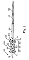
- FIG. 2 illustrates a perspective view of a delivery system and a prosthetic valve in accordance with the present invention prior to loading the prosthetic valve on the remainder of the system;
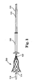
- FIG. 3 illustrates a subsequent step in the loading method from the illustration in FIG. 2 , in which the prosthetic valve is attached to a coil and is being collapsed from a proximal end so that it may be retracted into a loading funnel;
- FIG. 4 illustrates a subsequent step in the loading method from the illustration in FIG. 3 , in which the prosthetic valve is being collapsed and retracted into the loading funnel;
- FIG. 5 illustrates a subsequent step in the loading method from the illustration in FIG. 4 , in which the prosthetic valve is collapsed and retracted into the loading funnel;
- FIG. 6 illustrates a subsequent step in the loading method from the illustration in FIG. 5 , in which the prosthetic valve is retracted into an outer sheath;
- FIG. 7 illustrates a subsequent step in the loading method from the illustration in FIG. 6 , in which the prosthetic valve is enclosed in the outer sheath in a collapsed configuration and is ready for intraluminal insertion or delivery to a desired anatomic site;
- FIG. 8 illustrates a subsequent step from the loading method in FIG. 7 , in the delivery of the prosthetic valve, in which the outer sheath is partially retracted and the prosthetic valve is partially expanded;
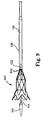
- FIG. 9 illustrates a subsequent step in the delivery of the prosthetic heart valve from the illustration in FIG. 8 , in which the outer sheath is retracted from the prosthetic valve and the prosthetic valve is partially expanded with the proximal end still attached to the coil;
- FIG. 10 illustrates a subsequent step in the delivery of the prosthetic valve from the illustration in FIG. 9 , in which the prosthetic valve is released from the delivery system;
- FIG. 11 illustrates an alternative embodiment of the delivery system of the present invention shown with the prosthetic valve partially expanded, which incorporates dye injection into the system and allows for purging of the system.
- the principles of the invention may be practiced in any instance in which it is desired to deliver a medical device intraluminally to a desired anatomic site.
- the medical device being loaded and delivered is a prosthetic valve, and specifically an infundibular reducer device.
- This illustrative context shows how corresponding embodiments of the invention are particularly useful for delivering an infundibular reducer, including a pericardial heart valve, a valved segment of bovine jugular vein, or some other collapsible valve, to the right ventricular outflow tract.
- an infundibular reducer including a pericardial heart valve, a valved segment of bovine jugular vein, or some other collapsible valve, to the right ventricular outflow tract.
- other uses of the invention such as to deliver different medical devices to different locations in the body, are contemplated and are not limited to those discussed in the application.
- FIGS. 1-10 wherein components are labeled with like numerals throughout the several Figures, an embodiment of a first aspect of the invention is shown, which is a delivery system 100. Steps of the related methods are also shown in the FIGS. 1-10 . The steps shown involve loading an infundibular reducer device 500 on the delivery system 100 and delivering the device 500.
- the delivery system 100 is illustrated in FIG. 1 .
- the system 100 includes a distal end generally designated by the reference numeral 102 and a proximal end generally designated by the reference number 104.
- the distal end 102 is preferably used to load and deliver an infundibular device, for example, which will be described in detail below.
- the proximal end 104 which is not shown in subsequent figures, preferably includes components such as those found in other catheter delivery systems.
- FIG. 1 includes a first rotating homeostasis valve 106, a side access port 108, a second rotating homeostasis valve 110, and a guidewire lumen inlet 112.
- the first rotating homeostasis valve 106 is most preferably comprised of latex and grips or forms a fluid seal around the delivery system 100 to prevent blood or other fluid from leaking out of the delivery device at the proximal end or entry site into a patient.
- the side access port 108 is provided as a means for injecting contrast media or saline, for example, into the delivery system 100.
- the second rotating homeostasis valve 110 is like first valve 106 in that it preferably prevents blood or other fluid from leaking back through the system 100.
- the second valve 110 is preferably configured to allow wires, devices and fluid to pass through.
- second valve 110 also preferably controls the components of the distal end (as described below) by rotation of a portion of the valve 110.
- the first and second valves 106, 110 are preferably compatible with normal catheter-laboratory components. Such first and second valves 106, 110 are preferably similar to those generally known in catheter systems.
- the delivery system 100 is preferably designed for use in the femoral artery.
- the useable length of the system 100 from the distal end 118 to an outer sleeve 116 is preferably about 100 to 105 centimeters, although other lengths are also contemplated.
- the proximal end 104 of the device preferably extends outside of the patient in the groin area, while the distal end 102 is preferably delivered intravascularly to an area at or near a pulmonary valve inside the body.
- Other uses for the system 100 in other areas of the body are also contemplated.
- the delivery system 100 is configured to allow for coaxial use to pass items such as guidewires, devices, contrast media and other catheters through the system 100.
- the delivery system 100 preferably includes an inner catheter 114 that includes a guidewire lumen, and is connected to a guidewire lumen inlet 112 at the proximal end of the inner catheter 114.
- the inner catheter 114 preferably extends along the entire length of the system 100 in order to allow a guidewire to pass from the proximal end 104 and out through the distal end 102.
- Inner catheter 114 may be slid or moved through other components of the system 100 by moving the guidewire lumen inlet 112 to which it is attached.
- the system 100 may include a guidewire, which may be, for example a 0.089 cm extra stiff guidewire as manufactured by Amplatzer, Golden Valley, Minnesota, U.S.A.
- the guidewire can be used to guide the delivery system 100 to its desired implant location, and can extend through the inner catheter 114.
- Other guidewires are also contemplated, however.
- the outer sleeve 116 preferably is located between the proximal end 104 and the distal end 102 of the system 100.
- the purpose of the sleeve 116 is to keep blood from leaking back around the delivery system 100.
- the components of the proximal end 104 of the system 100 are exemplary. Other alternative or additional components of the proximal end 104 of the delivery system 100 are also contemplated by the invention.
- FIG. 1 shows the distal end 102 of the system 100 in an assembled configuration, without an infundibular reducer device attached or loaded.
- Attached to the inner catheter 114 is a tapered tip 118, which serves to ease the passage of the delivery system 100 through the vasculature.
- a device holding catheter 120 upon which a prosthetic valve, or other medical device to be delivered, is attached or held during delivery.
- the holding catheter 120 includes a centrally located lumen surrounding the inner catheter 114.
- the holding catheter 120 is able to slide relative to the inner catheter 114, and its movement is controlled by the second valve 110 at the proximal end 104 of the system 100.
- a portion of second valve 110 is rotated or otherwise manipulated in order to rotates holding catheter 120 or moves the holding catheter 120 proximally and distally as desired.
- a coil 122 is preferably attached to the distal end of the holding catheter 120.
- movement of the holding catheter 120 controls movement or rotation of coil 122.
- the purpose of the coil 122 is to provide a means for loading a device 500 onto the system 100, holding the device 500 on the system 100 during delivery, and releasing the device 500 from the system 100.
- the speed that the device 500 is released from the system 100 is controlled by the rate of rotation of the coil 122, therefore preventing uncontrolled release of the device 500 in a manner known in the art as "jumping.”
- a reinforcement layer 124 Surrounding the holding catheter 120 is a reinforcement layer 124, which is attached or otherwise bonded to the holding catheter 120 and serves to reinforce the catheter 120.
- the distal end 102 of the delivery system 100 also includes the outer sheath 126 that is preferably made of a low friction and flexible material, such as polytetrafluoroethylene (PTFE), polyurethane, silicone, or polyethylene.
- the outer sheath 126 is sized and shaped in order to house other distal end 102 components of the delivery system 100.
- FIGS. 2-10 show the delivery system 100 of the invention, and show one exemplary medical device that can be delivered by the delivery system 100.
- the exemplary medical device 500 shown is a prosthetic valve, and in particular an infundibular reducer device 500, but is only one example of a medical device that may be delivered by the delivery system 100.
- FIG. 2 illustrates the exemplary infundibular reducer device 500 surrounding the distal end 102 of the system 100, but not yet attached to or loaded onto the system 100.
- the device 500 comprises a self-expandable stent portion 502 that may be expanded from a first reduced diameter to a second enlarged diameter.
- the device 500 is compressible to be inserted via catheter and expandable to fit a desired body lumen, such as the right ventricular outflow tract, for example.
- the self-expandable stent 502 is at least partially formed into its desired configuration using a material or materials and a form that may be compressed and that will regain the desired configuration upon release from compression.
- the stent portion 502 is preferably formed into a desired shape and made from a framework that comprises a wire or plurality of wires 504 made of a shape-memory material (e.g., NITINOLTM) and preferably one or more pieces of fabric 506 (i.e., cloth, material, etc.) to which the wire or wires 504 are attached.
- a shape-memory material e.g., NITINOLTM
- fabric 506 i.e., cloth, material, etc.
- the wires 504 of the stent 502 are shaped and aligned such that when the wires 504 are aligned generally coaxially, a central lumen runs along the length of the stent 502.
- the wires 504 preferably include a series of sinusoidal bends around their circumference, which allow for the compression and expansion of the stent 502 with minimal force.
- the wires may be attached separately to the fabric 506. In addition or alternatively, the wires 504 may be attached to each other at some or all of their adjacent apices.
- the stent 502 of the construction and configuration as herein described, preferably has good flexibility, dimensional stability, smooth surfaces, a low profile when collapsed, and an immunity to fatigue and corrosion.
- the length of the stent 502 can be varied by varying the number of wires 504 that are utilized, by varying the arrangement of wires and/or by varying other features of the wires and arrangement of wires.
- the working range of the stent 502 between its collapsed condition/configuration and its expanded condition can also be varied by the number of curves or bends in each wire.
- the stent 502 may be tailored for insertion into a particular body site to provide for the most effective implantation of the replacement valve which is attached to the stent 502.
- the fabric 506 used for the stent 502 can be a polyester knit, for example, or may instead be ultra high molecular weight polyethylene (UHMWPE), cotton, or the like.
- the fabric 506 should be biocompatible and may include a number of different fabrics in different areas of the stent 502 and/or in layers, if desired.
- the shape of the self-expandable stent 502 shown in the figures is one exemplary shape, and has a generally hourglass shape.
- Such an hourglass shape (with stent 502 in expanded configuration) includes a center 508 that is generally cylindrical in shape with a smaller diameter than ends 510.
- One advantage of the center 508 having a smaller diameter than the ends 510 is to allow at least a portion of the center 508 of the stent 502 to hold or retain a replacement valve (e.g., a pericardial heart valve or a valved segment of bovine jugular vein) in its central lumen (not seen in Figures), when such a replacement valve has a smaller diameter than the lumen in which the device 500 is to be placed.
- a replacement valve e.g., a pericardial heart valve or a valved segment of bovine jugular vein
- the larger diameter of the ends 510 allows the device 500 to be secured in place in a tubular organ, or a valved anatomic site, having a diameter larger than that of the replacement valve but smaller than the expanded diameter of the ends 510.
- the ends 510 are also shown to be flared, such that they increase in diameter from where the ends 510 extend from the center 508.
- the angle at which these ends 510 are flared from the center 508 can vary depending on the desired maximum diameter and desired length of the stent 502.
- the ends 510 can be articulable with respect to the center 508 when the wires 504 used for the framework of the center 508 and ends 510 are not attached to each other.
- the wires 504 of the center 508 may be attached to the wires 504 of one or both ends 510.
- the center 508 and ends 510 can still be articulable relative to each other.
- the replacement valve (not shown) preferably included in the prosthetic valve 500 is a preserved bovine jugular vein of the type described in the above-cited Bonhoeffer, et al. and Tower, et al. references. Other vessels or donor species may, however, alternatively be employed. Alternatively, other substantially tubular valve bodies may be the replacement valves of the invention. Such replacement valves may be formed from a variety of materials including biological materials and polymers. Biological material includes homograft, allograft or xenograft, with xenograft being common and well accepted and usually from bovine, ovine, swine or porcine pericardium, or a combination thereof.
- Polymers include expanded TEFLONTM polymers, high density polyethylene, polyurethane, and combinations thereof.
- replacement valves used in the invention are described in U.S. Patent Nos. 6,719,789 and 5,480,424 , issued to Cox
- the replacement valve is attached to (i.e., affixed to, held by, retained by, etc.) the stent 502, preferably, along its proximal and distal edges and is sutured or otherwise attached within the stent 502.
- the replacement valve is preferably positioned within the center 508 of the stent 502.
- the prosthetic valve 500 or other medical device, that is part of the delivery system 100 of the invention preferably includes, on its proximal end 512, a plurality of attachment members (not visible on figures, but present on proximal-most extensions 514 of device 500 on the proximal end 512 of device 500), such as loops, for example, that allow the prosthetic valve 500 or medical device to be loaded onto (and unloaded from) the delivery system 100.
- a plurality of attachment loops may be formed from sutures, from the fabric used to form part of the stent 502, or other materials.
- the attachment loops may be made of UHMWPE thread, for one example, since this material advantageously has the properties of being durable and lubricous, as well as hydrophobic, which can help to minimize swelling or clotting due to contact with blood.
- UHMWPE thread for one example, since this material advantageously has the properties of being durable and lubricous, as well as hydrophobic, which can help to minimize swelling or clotting due to contact with blood.
- other materials may be used that comprise some or all of these attachment loop properties.
- attachment members besides loops are also contemplated by the invention.
- Such attachment members are preferably able to connect, fasten or attach the medical device or prosthetic valve 500 to the remainder of the delivery system 100 and allow for collapse of the medical device or prosthetic valve 500 for insertion into the body, and also are preferably able to be released from the remainder of the delivery system 100 in order to release the medical device or prosthetic valve 500 at a desired anatomic site.
- the preferred delivery system 100 is illustrated in FIGS. 1-10 , and is generally long and tubular permitting percutaneous delivery of the device 500 to a placement site.
- the proximal end 104 of the delivery system 100 preferably remains outside of the patient, and the distal end 102 is inserted into the patient.
- the proximal end 104 allows access to the interior of the delivery system 100 and includes means for remotely controlling the distal end 102 of the system 100, in particular relating to loading and delivery of such a device 500 on the system 100.
- the prosthetic valve 500 is prepared to be loaded onto the delivery system 100.
- the loading is preferably done outside the body prior to insertion of the delivery system 100 into a vein or other body lumen.
- the loading involves extending the distal portion 102 of the delivery system 100, and specifically the inner catheter 114 and tapered tip 118, through a central lumen of the valve or device 500.
- the proximal end 512 of the prosthetic valve 500 in order to be loaded using the described method, includes attachment loops (not visible) preferably on its proximal-most extensions 514.
- the loops are preferably made of suture material or other material, as described above, and function to provide a way to connect or attach the prosthetic valve 500 to the remainder of the delivery system 100.
- a loading rail 400 is inserted through the attachment loops (not shown) on the proximal-most extensions 514 of device 500.
- the loading rail 400 is preferably flexible plastic tubing or similar material that is threaded through the attachment loops.
- the loading rail 400 has two free ends. Both free ends of the loading rail 400 preferably have a central lumen, hollow area. One of the free ends of the loading rail is cut at an angle to allow ease of insertion into the attachment loops and the other end is square cut to allow that free end to be placed on or otherwise attached to the coil 122.
- the loading rail 400 and coil 122 can be attached by a frictional fit (e.g., one of the loading rail 400 and coil 122 can slip over the other to connect the two components).
- FIG. 3 shows the proximal end 512 of the prosthetic valve 500 connected to the coil 122 as described, with the proximal end 512 of the valve 500 being compressed to closely match the diameter of the coil 122.
- a loading funnel 300 is used.
- the loading funnel 300 is shown in FIGS. 2 and 3 .
- the loading funnel 300 is preferably loaded onto the system 100 from the proximal end 104 of the system 100 to a location as shown in FIGS. 2 and 3 .
- the purpose of the loading funnel 300 is to gradually compress the prosthetic valve 500 for eventual enclosure in the system 100.
- the holding catheter 120 may be retracted proximally, which pulls or moves the device 500 proximally as well.
- the loading funnel 300 then is held in place in order for the device 500 to be compressed in the loading funnel 300.
- FIG. 4 shows the device 500 partially compressed in the loading funnel 300.
- the loading funnel could be advanced proximally causing the device 500 to be compressed by advancement of the loading funnel 300.
- FIG. 4 shows the loading funnel 300 surrounding and compressing a portion of the prosthetic valve 500.
- FIG. 5 shows the next step in which the prosthetic valve 500 is completely enclosed within the loading funnel 300, with the inner catheter 114 and tapered tip 118 still extending out and through the distal end of the holding catheter 120.
- FIG. 6 shows the collapsed prosthetic valve 500 even further retracted into the outer sheath 126.
- the device 500 is no longer inside the loading funnel 300.
- the outer sheath 126 then contains the collapsed prosthetic valve 500 in order to compress the prosthetic valve 100 to have a profile reduced enough to be inserted into a desired anatomic site, and to provide a smooth profile for insertion.
- the loading funnel 300 may then be removed from the remainder of the system 100.
- the loading funnel 300 is preferably removed from the remainder of the delivery system 100 by sliding it toward the distal end 102 of the system 100.
- the inner catheter 114 is then retracted or pulled proximally towards the outer sheath 126 until the tip 118 fits into the distal end of the outer sheath 126, enclosing the prosthetic valve 500 in the outer sleeve for insertion into the body.
- the distal end of the resulting, loaded delivery system 100 with prosthetic valve 500 is shown in FIG. 7.
- FIG. 7 shows the distal end of the delivery system 100 as it can be inserted intraluminally to a desired anatomic site for delivery of the prosthetic valve 500.
- the outer sheath 126 In order to deploy or release the prosthetic valve 500 once it has been positioned at its desired location in the vasculature or in a heart valve annulus, for example, the outer sheath 126 is either retracted proximally, or the device 500 is pushed out the end of the outer sheath 126 by the holding catheter 120. As shown, in FIG. 8 , the collapsed prosthetic valve 500 is begun to be released. In FIG. 9 , the outer sheath 126 has been further retracted until the outer sheath 126 no longer surrounds the prosthetic valve 500, while the proximal-most extensions 514 (via loops that are not visible on this figure) are still attached to the coil 122.
- the delivery process is reversible.
- the prosthetic valve 500 may be retracted back into the outer sheath 126 and the delivery system 100 may be reassembled in order to move the delivery system 100 to another location.
- the device 500 is released from within the outer sheath 126.
- the loops on the proximal-most extensions 514 of the device 500 are released from the coil 122 by remotely rotating the holding catheter 120 from the proximal end of the delivery system 100 (at second valve 110) until all of the loops are free from the coil 122.
- blood can flow through the system 100 at this point, thereby maintaining relatively normal heart function during the procedure.
- FIG. 10 shows the prosthetic valve 500 separated from the delivery system 100, with the delivery system 100 still extending through the lumen of the prosthetic valve 500.
- FIG. 11 Another embodiment of the present invention is shown in FIG. 11 , that includes two additional and alternative features of the present inventive system.
- a distal portion of a system 200 is shown in the figure.
- the components of system 100 as described above are also preferably in the embodiment shown in FIG. 11 , with corresponding numbers.
- the embodiment shown includes dye injection ports 250 near the distal end of the system 200, and preferably at or near the proximal end of the outer sheath 226.
- the dye injection ports 250 preferably comprise a plurality of apertures through the outer sheath 226 and to the interior of the system 200 such that dye introduced at the proximal end of the system 200 (not shown, but preferably delivered through an access port like 108 in system 100) travels through the system 200 and out through the dye injection ports 250.
- the purpose of the dye injection is to allow for proximal visual alignment of the device 500 being delivered.
- a partially deployed device 500 blocks flow.
- the dye injection ports 250 will introduce dye into the right ventricular chamber and allow for precise alignment of the device 500 in the right ventricular outflow tract.
- dye injection is used together with fluoroscopy for visualization.
- visualization may be achieved by using a procedure chosen from the group consisting of fluoroscopy, echocardiography, intravascular ultrasound, angioscopy and real-time magnetic resonance imaging, for examples.
- other similar methods of visualizing the area are also contemplated for use with the dye injection.
- FIG. 11 shows a plurality of purging vents 252 preferably located on the tapered tip 218 of the system 200.
- the purpose of the purging vents 252 is to allow fluids, such as saline, that is injected into the system 200 (such as by an access port like that of 108 in system 100) is able to escape the system 200. Such fluid may escape through a plurality of purging ports 252 preferably located near the distal end of system 200, rather than increase the pressure inside of system 200.
- a guide wire may be initially introduced into the desired implantation site through a suitable body lumen to properly locate the desired position for the stent. The remainder of the delivery system may then be guided along the guide wire and into the site.
- a prosthetic valve 500 made using bovine jugular vein or other preserved biological tissue, such as pericardial tissue the valve can be sterilized, stored and shipped separately in a buffered glutaraldehyde solution, and may or may not be pre-mounted on the delivery system 100 or 200.
- a loading rail 400 is loaded on the prosthetic valve 500 as stored.
- the prosthetic valve 500 can also be pre-mounted on the delivery system 100 or 200 if the system with the valve 500 mounted thereon is similarly sterilized and kept in a sterile environment. In many cases, however, an implanting physician or an assistant will perform the step of mounting the prosthetic valve 500 to the delivery system 100 or 200, as described above.
Landscapes
- Health & Medical Sciences (AREA)
- Cardiology (AREA)
- Engineering & Computer Science (AREA)
- Biomedical Technology (AREA)
- Life Sciences & Earth Sciences (AREA)
- Veterinary Medicine (AREA)
- Heart & Thoracic Surgery (AREA)
- Animal Behavior & Ethology (AREA)
- General Health & Medical Sciences (AREA)
- Public Health (AREA)
- Vascular Medicine (AREA)
- Transplantation (AREA)
- Oral & Maxillofacial Surgery (AREA)
- Anesthesiology (AREA)
- Hematology (AREA)
- Biophysics (AREA)
- Pulmonology (AREA)
- Prostheses (AREA)
Claims (12)
- Système de fourniture (100) destiné à fournir un dispositif à une lumière corporelle, le dispositif (500) comprenant une extrémité proximale (512) et une extrémité distale, une lumière centrale au travers, et une pluralité d'éléments de fixation situés sur ou près de l'extrémité proximale (512), le système étant caractérisé par :un cathéter intérieur allongé (114) présentant une extrémité proximale et une extrémité distale conique (118) pour insertion dans une lumière corporelle ;un cathéter de retenue allongé (120) présentant une extrémité proximale, une extrémité distale, une lumière centrale passant au travers pour maintenir le cathéter intérieur (114) de manière coulissante et une bobine (122) sur l'extrémité distale destinée à être fixée sur la pluralité d'éléments de fixation sur le dispositif ; etune gaine extérieure allongée (126) présentant des extrémités proximale et distale et une lumière centrale passant au travers pour maintenir le cathéter de retenue (120) de manière coulissante et rotative, pour fléchir le dispositif (500) lorsque le cathéter de retenue (120) est glissé de manière proximale au travers, et pour maintenir le dispositif (500) dans une configuration fléchie pour la fourniture vers une lumière corporelle.
- Système de fourniture selon la revendication 1, dans lequel la gaine extérieure comprend en outre un entonnoir (300) relié de manière amovible à l'extrémité distale pour fléchir le dispositif (500) lorsque le cathéter de retenue (120) est glissé au travers.
- Système de fourniture selon la revendication 1, comprenant en outre un rail de guidage (400) qui comprend un tube flexible essentiellement de forme circulaire avec deux extrémités libres, dans lequel le rail de guidage (400) peut être fixé à la pluralité d'éléments de fixation sur le dispositif (500) et comprend une première extrémité qui est fixée de manière amovible à la bobine (122) pour fournir un chemin continu pour les éléments de fixation du dispositif (500) à transférer du rail de guidage (400) vers la bobine (122).
- Système de fourniture selon la revendication 1, comprenant en outre le dispositif (500).
- Système de fourniture selon la revendication 1, dans lequel le dispositif (500) comprend en outre une valvule de remplacement qui est fixée à l'intérieur de la lumière centrale du dispositif.
- Système de fourniture selon la revendication 1, dans lequel la pluralité d'éléments de fixation comprend des boucles.
- Système de fourniture selon la revendication 1, comprenant en outre des ports d'injection de matière colorante (250) dans la gaine extérieure (226) à travers lesquels de la matière colorante peut s'écouler depuis le système vers une lumière corporelle.
- Système de fourniture selon la revendication 1, dans lequel le dispositif (500) est auto-expandable.
- Système de fourniture selon la revendication 1, comprenant en outre au moins un évent d'évacuation (252) sur ou près de l'extrémité distale du cathéter intérieur (214) à travers lequel du fluide injecté dans le cathéter intérieur (214) peut s'échapper du système.
- Procédé de chargement d'un dispositif sur un système de fourniture, le procédé comprenant les étapes de :réception d'un dispositif auto-expandable présentant une extrémité proximale et une extrémité distale, une lumière au travers, et une pluralité d'éléments de fixation situés sur ou près de l'extrémité proximale,réception d'un système de fourniture comprenant un rail de guidage avec deux extrémités libres, un cathéter intérieur allongé présentant une extrémité proximale et une extrémité distale conique, un cathéter de retenue allongé présentant une extrémité proximale et une extrémité distale comprenant une bobine pour fixation sur le dispositif et une lumière centrale passant au travers pour maintenir le cathéter intérieur et la bobine de manière coulissante, et une gaine extérieure allongée présentant une extrémité proximale et une extrémité distale et une lumière centrale passant au travers ;l'extension du cathéter intérieur à travers la lumière du cathéter de retenue et l'extension à la fois du cathéter intérieur et du cathéter de retenue à travers la lumière de la gaine extérieure ;le filetage de la pluralité d'éléments de fixation sur le long du rail de guidage ;la connexion d'une extrémité libre du rail de guidage à la bobine sur le cathéter de retenue ;l'avancée de la pluralité d'éléments de fixation le long du rail de guidage et sur la bobine, dans lequel la procédure d'avancée fléchit partiellement le dispositif ;le retrait du rail de guidage de la bobine après que tous les éléments de fixation sont transférés sur la bobine ;le fléchissement du dispositif dans la gaine extérieure en glissant la gaine extérieure au-dessus du dispositif ; etla clôture du dispositif fléchi en rétractant le cathéter intérieur de manière proximale et en tirant l'extrémité conique distale dans l'extrémité distale de la gaine extérieure.
- Procédé selon la revendication 10, dans lequel la pluralité d'éléments de fixation comprend des boucles.
- Procédé selon la revendication 10, dans lequel le dispositif est une valvule prothétique comprenant en outre une valvule de remplacement qui est fixée sur le dispositif à l'intérieur de la lumière centrale.
Applications Claiming Priority (2)
| Application Number | Priority Date | Filing Date | Title |
|---|---|---|---|
| US2333008P | 2008-01-24 | 2008-01-24 | |
| PCT/US2009/031766 WO2009094500A1 (fr) | 2008-01-24 | 2009-01-23 | Système de mise en place d'un dispositif réducteur de l'infundibulum et procédés apparentés |
Publications (2)
| Publication Number | Publication Date |
|---|---|
| EP2247263A1 EP2247263A1 (fr) | 2010-11-10 |
| EP2247263B1 true EP2247263B1 (fr) | 2011-08-03 |
Family
ID=40578246
Family Applications (1)
| Application Number | Title | Priority Date | Filing Date |
|---|---|---|---|
| EP09704185A Active EP2247263B1 (fr) | 2008-01-24 | 2009-01-23 | Système de mise en place d'un dispositif réducteur de l'infundibulum et procédés apparentés |
Country Status (6)
| Country | Link |
|---|---|
| US (2) | US9364324B2 (fr) |
| EP (1) | EP2247263B1 (fr) |
| AT (1) | ATE518502T1 (fr) |
| AU (1) | AU2009206340B2 (fr) |
| CA (1) | CA2712749A1 (fr) |
| WO (1) | WO2009094500A1 (fr) |
Cited By (16)
| Publication number | Priority date | Publication date | Assignee | Title |
|---|---|---|---|---|
| US10238487B2 (en) | 2008-08-22 | 2019-03-26 | Edwards Lifesciences Corporation | Prosthetic heart valve and delivery apparatus |
| US10856984B2 (en) | 2017-08-25 | 2020-12-08 | Neovasc Tiara Inc. | Sequentially deployed transcatheter mitral valve prosthesis |
| US10940001B2 (en) | 2012-05-30 | 2021-03-09 | Neovasc Tiara Inc. | Methods and apparatus for loading a prosthesis onto a delivery system |
| US11311376B2 (en) | 2019-06-20 | 2022-04-26 | Neovase Tiara Inc. | Low profile prosthetic mitral valve |
| US11357622B2 (en) | 2016-01-29 | 2022-06-14 | Neovase Tiara Inc. | Prosthetic valve for avoiding obstruction of outflow |
| US11389291B2 (en) | 2013-04-04 | 2022-07-19 | Neovase Tiara Inc. | Methods and apparatus for delivering a prosthetic valve to a beating heart |
| US11413139B2 (en) | 2011-11-23 | 2022-08-16 | Neovasc Tiara Inc. | Sequentially deployed transcatheter mitral valve prosthesis |
| US11419720B2 (en) | 2010-05-05 | 2022-08-23 | Neovasc Tiara Inc. | Transcatheter mitral valve prosthesis |
| US11464631B2 (en) | 2016-11-21 | 2022-10-11 | Neovasc Tiara Inc. | Methods and systems for rapid retraction of a transcatheter heart valve delivery system |
| US11491006B2 (en) | 2019-04-10 | 2022-11-08 | Neovasc Tiara Inc. | Prosthetic valve with natural blood flow |
| US11497602B2 (en) | 2012-02-14 | 2022-11-15 | Neovasc Tiara Inc. | Methods and apparatus for engaging a valve prosthesis with tissue |
| US11602429B2 (en) | 2019-04-01 | 2023-03-14 | Neovasc Tiara Inc. | Controllably deployable prosthetic valve |
| US11737872B2 (en) | 2018-11-08 | 2023-08-29 | Neovasc Tiara Inc. | Ventricular deployment of a transcatheter mitral valve prosthesis |
| US11779742B2 (en) | 2019-05-20 | 2023-10-10 | Neovasc Tiara Inc. | Introducer with hemostasis mechanism |
| US11998447B2 (en) | 2019-03-08 | 2024-06-04 | Neovasc Tiara Inc. | Retrievable prosthesis delivery system |
| US12109111B2 (en) | 2015-12-15 | 2024-10-08 | Neovasc Tiara Inc. | Transseptal delivery system |
Families Citing this family (185)
| Publication number | Priority date | Publication date | Assignee | Title |
|---|---|---|---|---|
| CA2580053C (fr) | 2004-09-14 | 2014-07-08 | Edwards Lifesciences Ag. | Dispositif et procede de traitement de la regurgitation valvulaire |
| DE102005003632A1 (de) | 2005-01-20 | 2006-08-17 | Fraunhofer-Gesellschaft zur Förderung der angewandten Forschung e.V. | Katheter für die transvaskuläre Implantation von Herzklappenprothesen |
| US20100312333A1 (en) | 2009-04-29 | 2010-12-09 | The Cleveland Clinic Foundation | Apparatus and method for replacing a diseased cardiac valve |
| WO2007058857A2 (fr) | 2005-11-10 | 2007-05-24 | Arshad Quadri | Stent de raccordement de prothese vasculaire, a deploiement automatique, pouvant etre deploye par ballonnet |
| US20090306768A1 (en) * | 2006-07-28 | 2009-12-10 | Cardiaq Valve Technologies, Inc. | Percutaneous valve prosthesis and system and method for implanting same |
| US7896915B2 (en) | 2007-04-13 | 2011-03-01 | Jenavalve Technology, Inc. | Medical device for treating a heart valve insufficiency |
| DE102007043830A1 (de) | 2007-09-13 | 2009-04-02 | Lozonschi, Lucian, Madison | Herzklappenstent |
| US9044318B2 (en) | 2008-02-26 | 2015-06-02 | Jenavalve Technology Gmbh | Stent for the positioning and anchoring of a valvular prosthesis |
| WO2011104269A1 (fr) | 2008-02-26 | 2011-09-01 | Jenavalve Technology Inc. | Stent pour le positionnement et l'ancrage d'une prothèse valvulaire dans un site d'implantation dans le cœur d'un patient |
| EP2282684B1 (fr) * | 2008-04-03 | 2016-06-15 | Cook Medical Technologies LLC | Dispositif d occlusion |
| US20090276040A1 (en) | 2008-05-01 | 2009-11-05 | Edwards Lifesciences Corporation | Device and method for replacing mitral valve |
| US8323335B2 (en) | 2008-06-20 | 2012-12-04 | Edwards Lifesciences Corporation | Retaining mechanisms for prosthetic valves and methods for using |
| CA2749026C (fr) | 2008-09-29 | 2018-01-09 | Impala, Inc. | Valvule cardiaque |
| CA2739275C (fr) | 2008-10-01 | 2017-01-17 | Impala, Inc. | Systeme de mise en place pour implant vasculaire |
| JP5607639B2 (ja) * | 2008-10-10 | 2014-10-15 | サドラ メディカル インコーポレイテッド | 医療用デバイス・システム |
| AU2009317876B2 (en) | 2008-11-21 | 2014-01-16 | Percutaneous Cardiovascular Solutions Pty Limited | Heart valve prosthesis and method |
| US8021420B2 (en) * | 2009-03-12 | 2011-09-20 | Medtronic Vascular, Inc. | Prosthetic valve delivery system |
| AU2010236288A1 (en) | 2009-04-15 | 2011-10-20 | Cardiaq Valve Technologies, Inc. | Vascular implant and delivery system |
| IN2012DN02041A (fr) * | 2009-08-28 | 2015-08-21 | 3F Therapeutics Inc | |
| US9730790B2 (en) | 2009-09-29 | 2017-08-15 | Edwards Lifesciences Cardiaq Llc | Replacement valve and method |
| RU140821U1 (ru) * | 2009-11-02 | 2014-05-20 | Симетис Са | Аортальный биопротез и системы для его доставки в место имплантации |
| US8983574B2 (en) | 2009-11-17 | 2015-03-17 | The Brigham And Women's Hospital | Catheter device with local magnetic resonance imaging coil and methods for use thereof |
| US8449599B2 (en) | 2009-12-04 | 2013-05-28 | Edwards Lifesciences Corporation | Prosthetic valve for replacing mitral valve |
| US8870950B2 (en) | 2009-12-08 | 2014-10-28 | Mitral Tech Ltd. | Rotation-based anchoring of an implant |
| EP4643824A3 (fr) * | 2009-12-08 | 2026-01-07 | Avalon Medical Ltd. | Dispositif et système de remplacement de valvule mitrale par transcathéter |
| US10856978B2 (en) | 2010-05-20 | 2020-12-08 | Jenavalve Technology, Inc. | Catheter system |
| CA2799459A1 (fr) | 2010-05-25 | 2011-12-01 | Jenavalve Technology Inc. | Valvule prothetique et endoprothese mise en place par catheterisme comprenant une valvule prothetique et un stent |
| EP2582326B2 (fr) | 2010-06-21 | 2024-07-03 | Edwards Lifesciences CardiAQ LLC | Prothèse de valvule cardiaque |
| US8657872B2 (en) | 2010-07-19 | 2014-02-25 | Jacques Seguin | Cardiac valve repair system and methods of use |
| US11653910B2 (en) | 2010-07-21 | 2023-05-23 | Cardiovalve Ltd. | Helical anchor implantation |
| EP3459500B1 (fr) | 2010-09-23 | 2020-09-16 | Edwards Lifesciences CardiAQ LLC | Valvules cardiaques de remplacement et dispositifs |
| US9775982B2 (en) | 2010-12-29 | 2017-10-03 | Medtronic, Inc. | Implantable medical device fixation |
| US10112045B2 (en) | 2010-12-29 | 2018-10-30 | Medtronic, Inc. | Implantable medical device fixation |
| WO2012092143A1 (fr) * | 2010-12-30 | 2012-07-05 | Boston Scientific Scimed, Inc. | Panier de chargement pour système de mise en place d'une endoprothèse |
| US12502276B2 (en) | 2011-05-16 | 2025-12-23 | Edwards Lifesciences Corporation | Inversion delivery device and method for a prosthesis |
| CA2957442C (fr) | 2011-08-11 | 2019-06-04 | Tendyne Holdings, Inc. | Ameliorations apportees a des valves prothetiques et inventions associees |
| CN102462565B (zh) * | 2011-10-25 | 2014-03-26 | 张石江 | 可回收可调节血管内缩窄介入支架 |
| US9827092B2 (en) | 2011-12-16 | 2017-11-28 | Tendyne Holdings, Inc. | Tethers for prosthetic mitral valve |
| CN108283534B (zh) | 2012-01-31 | 2019-09-24 | 米特拉尔维尔福科技有限责任公司 | 二尖瓣停放装置和系统 |
| US9717421B2 (en) * | 2012-03-26 | 2017-08-01 | Medtronic, Inc. | Implantable medical device delivery catheter with tether |
| US9833625B2 (en) | 2012-03-26 | 2017-12-05 | Medtronic, Inc. | Implantable medical device delivery with inner and outer sheaths |
| US9339197B2 (en) * | 2012-03-26 | 2016-05-17 | Medtronic, Inc. | Intravascular implantable medical device introduction |
| US10485435B2 (en) * | 2012-03-26 | 2019-11-26 | Medtronic, Inc. | Pass-through implantable medical device delivery catheter with removeable distal tip |
| US9854982B2 (en) | 2012-03-26 | 2018-01-02 | Medtronic, Inc. | Implantable medical device deployment within a vessel |
| US9220906B2 (en) | 2012-03-26 | 2015-12-29 | Medtronic, Inc. | Tethered implantable medical device deployment |
| US9144510B2 (en) | 2012-06-13 | 2015-09-29 | Cook Medical Technologies Llc | Systems and methods for deploying a portion of a stent using at least one coiled member |
| US9173756B2 (en) | 2012-06-13 | 2015-11-03 | Cook Medical Technologies Llc | Systems and methods for deploying a portion of a stent using at least one coiled member |
| WO2014022124A1 (fr) | 2012-07-28 | 2014-02-06 | Tendyne Holdings, Inc. | Conceptions multi-composantes améliorées pour dispositif de récupération de valve cardiaque, structures d'étanchéité et ensemble stent |
| WO2014021905A1 (fr) | 2012-07-30 | 2014-02-06 | Tendyne Holdings, Inc. | Systèmes et procédés d'administration améliorée pour valvules prothétiques transcathéter |
| US20150351906A1 (en) | 2013-01-24 | 2015-12-10 | Mitraltech Ltd. | Ventricularly-anchored prosthetic valves |
| US9439763B2 (en) | 2013-02-04 | 2016-09-13 | Edwards Lifesciences Corporation | Prosthetic valve for replacing mitral valve |
| US10583002B2 (en) | 2013-03-11 | 2020-03-10 | Neovasc Tiara Inc. | Prosthetic valve with anti-pivoting mechanism |
| US20140277427A1 (en) | 2013-03-14 | 2014-09-18 | Cardiaq Valve Technologies, Inc. | Prosthesis for atraumatically grasping intralumenal tissue and methods of delivery |
| US9730791B2 (en) | 2013-03-14 | 2017-08-15 | Edwards Lifesciences Cardiaq Llc | Prosthesis for atraumatically grasping intralumenal tissue and methods of delivery |
| US9681951B2 (en) | 2013-03-14 | 2017-06-20 | Edwards Lifesciences Cardiaq Llc | Prosthesis with outer skirt and anchors |
| US9439796B2 (en) * | 2013-03-15 | 2016-09-13 | Cook Medical Technologies Llc | Prosthesis delivery device |
| US11224510B2 (en) | 2013-04-02 | 2022-01-18 | Tendyne Holdings, Inc. | Prosthetic heart valve and systems and methods for delivering the same |
| US10463489B2 (en) | 2013-04-02 | 2019-11-05 | Tendyne Holdings, Inc. | Prosthetic heart valve and systems and methods for delivering the same |
| US9486306B2 (en) | 2013-04-02 | 2016-11-08 | Tendyne Holdings, Inc. | Inflatable annular sealing device for prosthetic mitral valve |
| US10478293B2 (en) | 2013-04-04 | 2019-11-19 | Tendyne Holdings, Inc. | Retrieval and repositioning system for prosthetic heart valve |
| US9610159B2 (en) | 2013-05-30 | 2017-04-04 | Tendyne Holdings, Inc. | Structural members for prosthetic mitral valves |
| EP3415120B1 (fr) | 2013-06-25 | 2022-12-14 | Tendyne Holdings, Inc. | Caractéristiques de gestion de thrombus et de conformité structurelle pour valvules cardiaques prothétiques |
| WO2015013666A1 (fr) | 2013-07-26 | 2015-01-29 | Cardiaq Valve Technologies, Inc. | Systèmes et procédés pour sceller des ouvertures dans une paroi anatomique |
| CN105555231B (zh) | 2013-08-01 | 2018-02-09 | 坦迪尼控股股份有限公司 | 心外膜锚固装置和方法 |
| CR20160094A (es) | 2013-08-14 | 2018-03-05 | Mitral Valve Tech Sarl | Equipo y métodos para implantar una válvula cardiaca de reemplazo |
| CN105491978A (zh) | 2013-08-30 | 2016-04-13 | 耶拿阀门科技股份有限公司 | 用于假体瓣膜的径向可折叠框架及其制造方法 |
| WO2015058039A1 (fr) | 2013-10-17 | 2015-04-23 | Robert Vidlund | Appareil et procedes d'alignement et de deploiement de dispositifs intracardiaques |
| CN105682611B (zh) | 2013-10-28 | 2018-06-01 | 坦迪尼控股股份有限公司 | 假体心脏瓣膜以及用于输送假体心脏瓣膜的系统和方法 |
| US9526611B2 (en) | 2013-10-29 | 2016-12-27 | Tendyne Holdings, Inc. | Apparatus and methods for delivery of transcatheter prosthetic valves |
| CN104586542B (zh) * | 2013-10-31 | 2017-01-04 | 上海微创心通医疗科技有限公司 | 一种将植入体装载到输送系统中的装置和方法 |
| WO2015120122A2 (fr) | 2014-02-05 | 2015-08-13 | Robert Vidlund | Appareil et procédés pour la mise en place d'une valve mitrale prothétique par l'artère fémorale |
| US9986993B2 (en) | 2014-02-11 | 2018-06-05 | Tendyne Holdings, Inc. | Adjustable tether and epicardial pad system for prosthetic heart valve |
| ES3037253T3 (en) | 2014-02-20 | 2025-09-30 | Mitral Valve Tech Sarl | A system for implanting a prosthetic heart valve supported by a coiled anchor |
| SG11201606230YA (en) | 2014-02-21 | 2016-08-30 | Mitral Valve Technologies Sarl | Devices, systems and methods for delivering a prosthetic mitral valve and anchoring device |
| WO2015127283A1 (fr) | 2014-02-21 | 2015-08-27 | Cardiaq Valve Technologies, Inc. | Dispositif d'acheminement pour le déploiement maîtrisé d'une de valvule de substitution |
| USD755384S1 (en) | 2014-03-05 | 2016-05-03 | Edwards Lifesciences Cardiaq Llc | Stent |
| JP6865037B2 (ja) | 2014-03-10 | 2021-04-28 | テンダイン ホールディングス,インコーポレイテッド | 人工僧帽弁を位置決めするため及び人工僧帽弁のテザーの荷重を監視するためのデバイス及び方法 |
| CA3161000A1 (fr) | 2014-05-19 | 2015-11-26 | Edwards Lifesciences Cardiaq Llc | Valvule mitrale de remplacement ayant un rabat annulaire |
| US9532870B2 (en) | 2014-06-06 | 2017-01-03 | Edwards Lifesciences Corporation | Prosthetic valve for replacing a mitral valve |
| WO2016016899A1 (fr) | 2014-07-30 | 2016-02-04 | Mitraltech Ltd. | Prothèse valvulaire articulable |
| US10016272B2 (en) | 2014-09-12 | 2018-07-10 | Mitral Valve Technologies Sarl | Mitral repair and replacement devices and methods |
| CA2962747C (fr) | 2014-09-28 | 2023-02-28 | Cardiokinetix, Inc. | Appareils permettant de traiter un dysfonctionnement cardiaque |
| ES2989081T3 (es) | 2014-11-26 | 2024-11-25 | Edwards Lifesciences Corp | Válvula cardíaca protésica transcatéter y sistema de suministro |
| AU2016205371B2 (en) | 2015-01-07 | 2019-10-10 | Tendyne Holdings, Inc. | Prosthetic mitral valves and apparatus and methods for delivery of same |
| CA2973940C (fr) | 2015-02-05 | 2022-08-23 | Mitraltech Ltd. | Valve prothetique avec cadres coulissant axialement |
| EP3253331B1 (fr) | 2015-02-05 | 2021-04-07 | Tendyne Holdings, Inc. | Valvule cardiac prothétique avec câble d'attache et tampon épicardique expansible |
| EP3270825B1 (fr) | 2015-03-20 | 2020-04-22 | JenaValve Technology, Inc. | Système de pose de prothèse de valvule cardiaque |
| EP3271000B1 (fr) | 2015-03-20 | 2020-06-17 | Cardiokinetix, Inc. | Systèmes de placement d'un dispositif implantable |
| AU2016248314B2 (en) * | 2015-04-16 | 2020-05-21 | Tendyne Holdings, Inc. | Apparatus and methods for delivery, repositioning, and retrieval of transcatheter prosthetic valves |
| US10441416B2 (en) | 2015-04-21 | 2019-10-15 | Edwards Lifesciences Corporation | Percutaneous mitral valve replacement device |
| US10376363B2 (en) | 2015-04-30 | 2019-08-13 | Edwards Lifesciences Cardiaq Llc | Replacement mitral valve, delivery system for replacement mitral valve and methods of use |
| EP3632378B1 (fr) | 2015-05-01 | 2024-05-29 | JenaValve Technology, Inc. | Dispositif à faible débit de stimulateur cardiaque dans le remplacement de valvule cardiaque |
| US10226335B2 (en) | 2015-06-22 | 2019-03-12 | Edwards Lifesciences Cardiaq Llc | Actively controllable heart valve implant and method of controlling same |
| US10092400B2 (en) | 2015-06-23 | 2018-10-09 | Edwards Lifesciences Cardiaq Llc | Systems and methods for anchoring and sealing a prosthetic heart valve |
| CN113384384A (zh) * | 2015-06-29 | 2021-09-14 | 莱拉医药公司 | 支架装载和递送系统 |
| US10117744B2 (en) | 2015-08-26 | 2018-11-06 | Edwards Lifesciences Cardiaq Llc | Replacement heart valves and methods of delivery |
| US10575951B2 (en) | 2015-08-26 | 2020-03-03 | Edwards Lifesciences Cardiaq Llc | Delivery device and methods of use for transapical delivery of replacement mitral valve |
| US10350066B2 (en) | 2015-08-28 | 2019-07-16 | Edwards Lifesciences Cardiaq Llc | Steerable delivery system for replacement mitral valve and methods of use |
| US10327894B2 (en) | 2015-09-18 | 2019-06-25 | Tendyne Holdings, Inc. | Methods for delivery of prosthetic mitral valves |
| CA3005908A1 (fr) | 2015-12-03 | 2017-06-08 | Tendyne Holdings, Inc. | Attributs de cadre pour valvules mitrales prothetiques |
| AU2016380259B2 (en) | 2015-12-28 | 2020-10-22 | Tendyne Holdings, Inc. | Atrial pocket closures for prosthetic heart valves |
| US10363130B2 (en) | 2016-02-05 | 2019-07-30 | Edwards Lifesciences Corporation | Devices and systems for docking a heart valve |
| US10531866B2 (en) | 2016-02-16 | 2020-01-14 | Cardiovalve Ltd. | Techniques for providing a replacement valve and transseptal communication |
| USD815744S1 (en) | 2016-04-28 | 2018-04-17 | Edwards Lifesciences Cardiaq Llc | Valve frame for a delivery system |
| US10470877B2 (en) | 2016-05-03 | 2019-11-12 | Tendyne Holdings, Inc. | Apparatus and methods for anterior valve leaflet management |
| US11065138B2 (en) | 2016-05-13 | 2021-07-20 | Jenavalve Technology, Inc. | Heart valve prosthesis delivery system and method for delivery of heart valve prosthesis with introducer sheath and loading system |
| US11039921B2 (en) | 2016-06-13 | 2021-06-22 | Tendyne Holdings, Inc. | Sequential delivery of two-part prosthetic mitral valve |
| EP3478224B1 (fr) | 2016-06-30 | 2022-11-02 | Tendyne Holdings, Inc. | Valves cardiaques prothétiques et appareil associés de mise en place |
| US10828150B2 (en) | 2016-07-08 | 2020-11-10 | Edwards Lifesciences Corporation | Docking station for heart valve prosthesis |
| EP3484411A1 (fr) | 2016-07-12 | 2019-05-22 | Tendyne Holdings, Inc. | Appareil et procédés de récupération transseptale de valvules cardiaques prothétiques |
| US10350062B2 (en) | 2016-07-21 | 2019-07-16 | Edwards Lifesciences Corporation | Replacement heart valve prosthesis |
| GB201613219D0 (en) | 2016-08-01 | 2016-09-14 | Mitraltech Ltd | Minimally-invasive delivery systems |
| CN109789017B (zh) | 2016-08-19 | 2022-05-31 | 爱德华兹生命科学公司 | 用于置换二尖瓣的可转向递送系统和使用方法 |
| EP4454613A3 (fr) | 2016-08-26 | 2025-01-29 | Edwards Lifesciences Corporation | Prothèse de valvule cardiaque de remplacement à portions multiples |
| US10722359B2 (en) | 2016-08-26 | 2020-07-28 | Edwards Lifesciences Corporation | Heart valve docking devices and systems |
| CR20190069A (es) | 2016-08-26 | 2019-05-14 | Edwards Lifesciences Corp | Valvulas y sistemas de acoplamiento de valvulas corazon |
| US12329641B2 (en) | 2016-08-26 | 2025-06-17 | Edwards Lifesciences Corporation | Heart valve docking devices and systems |
| US10758348B2 (en) | 2016-11-02 | 2020-09-01 | Edwards Lifesciences Corporation | Supra and sub-annular mitral valve delivery system |
| CN110381897A (zh) | 2016-12-29 | 2019-10-25 | 波士顿科学国际有限公司 | 用于将支架装载至递送装置中的方法 |
| US11013600B2 (en) | 2017-01-23 | 2021-05-25 | Edwards Lifesciences Corporation | Covered prosthetic heart valve |
| US11654023B2 (en) | 2017-01-23 | 2023-05-23 | Edwards Lifesciences Corporation | Covered prosthetic heart valve |
| US11185406B2 (en) | 2017-01-23 | 2021-11-30 | Edwards Lifesciences Corporation | Covered prosthetic heart valve |
| CN110392557A (zh) | 2017-01-27 | 2019-10-29 | 耶拿阀门科技股份有限公司 | 心脏瓣膜模拟 |
| USD867595S1 (en) | 2017-02-01 | 2019-11-19 | Edwards Lifesciences Corporation | Stent |
| WO2018157177A1 (fr) * | 2017-02-27 | 2018-08-30 | Thuy Pham | Nouveau dispositif de remplacement de valve transcathéter |
| EP3372199A1 (fr) * | 2017-03-08 | 2018-09-12 | Epygon | Système d'administration de valvule cardiaque par transcathéter |
| US10959846B2 (en) | 2017-05-10 | 2021-03-30 | Edwards Lifesciences Corporation | Mitral valve spacer device |
| US10842619B2 (en) | 2017-05-12 | 2020-11-24 | Edwards Lifesciences Corporation | Prosthetic heart valve docking assembly |
| EP3644902B1 (fr) | 2017-06-30 | 2024-05-22 | Edwards Lifesciences Corporation | Mécanismes de verrouillage et de déverrouillage pour dispositifs implantables trans-cathéters |
| CA3068313A1 (fr) | 2017-06-30 | 2019-01-03 | Edwards Lifesciences Corporation | Valves transcatheter de stations d'accueil |
| ES2923913T3 (es) | 2017-07-06 | 2022-10-03 | Edwards Lifesciences Corp | Sistema de suministro de carril orientable |
| JP7216066B2 (ja) | 2017-07-13 | 2023-01-31 | テンダイン ホールディングス,インコーポレイテッド | 人工心臓弁とその送達のための装置および方法 |
| US12064347B2 (en) | 2017-08-03 | 2024-08-20 | Cardiovalve Ltd. | Prosthetic heart valve |
| US11793633B2 (en) | 2017-08-03 | 2023-10-24 | Cardiovalve Ltd. | Prosthetic heart valve |
| USD890333S1 (en) | 2017-08-21 | 2020-07-14 | Edwards Lifesciences Corporation | Heart valve docking coil |
| CN111031967B (zh) | 2017-08-28 | 2022-08-09 | 坦迪尼控股股份有限公司 | 具有系带连接特征的人造心脏瓣膜 |
| US10881511B2 (en) | 2017-09-19 | 2021-01-05 | Cardiovalve Ltd. | Prosthetic valve with tissue anchors configured to exert opposing clamping forces on native valve tissue |
| US12458493B2 (en) | 2017-09-19 | 2025-11-04 | Cardiovalve Ltd. | Prosthetic heart valve and delivery systems and methods |
| WO2019147846A2 (fr) | 2018-01-25 | 2019-08-01 | Edwards Lifesciences Corporation | Système de distribution pour recapture de valvule de remplacement assistée et post-déploiement de repositionnement |
| US11051934B2 (en) | 2018-02-28 | 2021-07-06 | Edwards Lifesciences Corporation | Prosthetic mitral valve with improved anchors and seal |
| WO2019195860A2 (fr) | 2018-04-04 | 2019-10-10 | Vdyne, Llc | Dispositifs et procédés d'ancrage d'une valvule cardiaque transcathéter |
| WO2020041495A1 (fr) | 2018-08-21 | 2020-02-27 | Shifamed, Llc | Dispositifs, systèmes et méthodes pour valvule cardiaque prothétique |
| US12310850B2 (en) | 2018-09-20 | 2025-05-27 | Vdyne, Inc. | Transcatheter deliverable prosthetic heart valves and methods of delivery |
| US12186187B2 (en) | 2018-09-20 | 2025-01-07 | Vdyne, Inc. | Transcatheter deliverable prosthetic heart valves and methods of delivery |
| US10874850B2 (en) | 2018-09-28 | 2020-12-29 | Medtronic, Inc. | Impedance-based verification for delivery of implantable medical devices |
| US10912644B2 (en) | 2018-10-05 | 2021-02-09 | Shifamed Holdings, Llc | Prosthetic cardiac valve devices, systems, and methods |
| WO2020082039A1 (fr) | 2018-10-19 | 2020-04-23 | Shifamed Holdings, Llc | Dispositif médical réglable |
| WO2020086727A1 (fr) * | 2018-10-25 | 2020-04-30 | Cephea Valve Technologies, Inc. | Dispositifs et systèmes de chargement de valvule cardiaque |
| US11253359B2 (en) | 2018-12-20 | 2022-02-22 | Vdyne, Inc. | Proximal tab for side-delivered transcatheter heart valves and methods of delivery |
| WO2020146842A1 (fr) | 2019-01-10 | 2020-07-16 | Vdyne, Llc | Crochet d'ancrage pour prothèse de valvule cardiaque transcathéter à distribution latérale |
| US11273032B2 (en) | 2019-01-26 | 2022-03-15 | Vdyne, Inc. | Collapsible inner flow control component for side-deliverable transcatheter heart valve prosthesis |
| EP3921012A1 (fr) | 2019-02-04 | 2021-12-15 | Edwards Lifesciences Corporation | Appareil à fil de guidage et méthodes |
| GB201901887D0 (en) | 2019-02-11 | 2019-04-03 | Cardiovalve Ltd | Device for conditioning ex vivo pericardial tissue |
| EP4729034A2 (fr) | 2019-03-05 | 2026-04-22 | VDyne, Inc. | Dispositifs de commande de régurgitation tricuspide pour prothèse de valvule cardiaque par transcathéter orthogonal |
| US11173027B2 (en) | 2019-03-14 | 2021-11-16 | Vdyne, Inc. | Side-deliverable transcatheter prosthetic valves and methods for delivering and anchoring the same |
| US12447014B2 (en) | 2019-04-12 | 2025-10-21 | Edwards Lifesciences Corporation | Valve with multi-part frame and associated resilient bridging features |
| ES2982566T3 (es) | 2019-04-23 | 2024-10-16 | Edwards Lifesciences Corp | Sistema de suministro de implantes motorizado |
| AU2020267390B2 (en) | 2019-05-04 | 2025-12-04 | Vdyne, Inc. | Cinch device and method for deployment of a side-delivered prosthetic heart valve in a native annulus |
| US12151100B2 (en) | 2019-05-07 | 2024-11-26 | Medtronic, Inc. | Tether assemblies for medical device delivery systems |
| US11331475B2 (en) | 2019-05-07 | 2022-05-17 | Medtronic, Inc. | Tether assemblies for medical device delivery systems |
| CA3140397A1 (fr) | 2019-06-07 | 2020-12-10 | Edwards Lifesciences Corporation | Systemes, dispositifs et procedes de traitement de valvules cardiaques |
| WO2021035032A1 (fr) * | 2019-08-20 | 2021-02-25 | Vdyne, Inc. | Dispositifs d'administration et de récupération et procédés pour valvules prothétiques transcathéter à pose latérale |
| EP3831343B1 (fr) | 2019-12-05 | 2024-01-31 | Tendyne Holdings, Inc. | Ancrage tressé pour valvule mitrale |
| US11648114B2 (en) | 2019-12-20 | 2023-05-16 | Tendyne Holdings, Inc. | Distally loaded sheath and loading funnel |
| IL319705B2 (en) | 2020-02-06 | 2026-03-01 | Laplace Interventional Inc | A transcatheter heart valve prosthesis is implanted within the heart chambers or blood vessels. |
| WO2021178560A1 (fr) * | 2020-03-03 | 2021-09-10 | Shifamed Holdings, Llc | Dispositifs, systèmes et méthodes pour valvules cardiaques prothétiques |
| US11951002B2 (en) | 2020-03-30 | 2024-04-09 | Tendyne Holdings, Inc. | Apparatus and methods for valve and tether fixation |
| US12016774B2 (en) | 2020-05-08 | 2024-06-25 | Medtronic Vascular, Inc. | Delivery system for prosthetic valve device having controlled release of inflow and outflow ends |
| CN115916113A (zh) * | 2020-06-03 | 2023-04-04 | 美敦力公司 | 具有用于改进的经导管心脏瓣膜的定位的控制释放轴的递送装置 |
| WO2022040118A1 (fr) | 2020-08-17 | 2022-02-24 | Edwards Lifesciences Corporation | Cadre implantable et mécanisme de retenue de cadre |
| EP4199860A1 (fr) | 2020-08-19 | 2023-06-28 | Tendyne Holdings, Inc. | Tampon apical entièrement transseptal doté d'une poulie pour la mise sous tension |
| JP7821166B2 (ja) | 2020-08-31 | 2026-02-26 | シファメド・ホールディングス・エルエルシー | 人工弁送達システム |
| US12357459B2 (en) | 2020-12-03 | 2025-07-15 | Cardiovalve Ltd. | Transluminal delivery system |
| JP7835754B2 (ja) * | 2020-12-04 | 2026-03-25 | シファメド・ホールディングス・エルエルシー | 張り出し人工心弁送達デバイスおよびシステム |
| EP4247297A1 (fr) | 2020-12-18 | 2023-09-27 | Edwards Lifesciences Corporation | Ensemble bocal de stockage pour valvule cardiaque prothétique |
| US11951004B2 (en) | 2021-02-28 | 2024-04-09 | Medtronic, Inc. | Prosthetic valve device resistant to backfolding and buckling |
| US12201521B2 (en) | 2021-03-22 | 2025-01-21 | Shifamed Holdings, Llc | Anchor position verification for prosthetic cardiac valve devices |
| US12263083B2 (en) | 2021-05-05 | 2025-04-01 | Medtronic, Inc. | Systems for transcatheter prosthesis delivery and methods |
| EP4422552A1 (fr) | 2021-10-27 | 2024-09-04 | Edwards Lifesciences Corporation | Système et procédé de préhension et de chargement d'une valve cardiaque prothétique |
| KR20250003867A (ko) * | 2022-04-18 | 2025-01-07 | 보스톤 싸이엔티픽 싸이메드 인코포레이티드 | 다수의 플레어 및 숄더 이동 방지 스텐트 |
| EP4601585A1 (fr) | 2022-10-14 | 2025-08-20 | Vdyne, Inc. | Dispositifs et procédés de pose d'une valve cardiaque prothétique à l'aide d'un support supra-annulaire |
| US12171658B2 (en) | 2022-11-09 | 2024-12-24 | Jenavalve Technology, Inc. | Catheter system for sequential deployment of an expandable implant |
| US20240350266A1 (en) | 2023-04-21 | 2024-10-24 | Medtronic, Inc. | Prosthetic heart valve implant apparatus |
| WO2024256992A1 (fr) | 2023-06-14 | 2024-12-19 | Medtronic, Inc. | Prothèses de valvule cardiaque avec capteur pour surveillance hémodynamique |
| US12440336B1 (en) | 2025-02-11 | 2025-10-14 | Laplace Interventional Inc. | Prosthetic heart valves |
Family Cites Families (30)
| Publication number | Priority date | Publication date | Assignee | Title |
|---|---|---|---|---|
| US5749920A (en) * | 1983-12-09 | 1998-05-12 | Endovascular Technologies, Inc. | Multicapsule intraluminal grafting system and method |
| US5234437A (en) * | 1991-12-12 | 1993-08-10 | Target Therapeutics, Inc. | Detachable pusher-vasoocclusion coil assembly with threaded coupling |
| US5480424A (en) | 1993-11-01 | 1996-01-02 | Cox; James L. | Heart valve replacement using flexible tubes |
| US5713950A (en) | 1993-11-01 | 1998-02-03 | Cox; James L. | Method of replacing heart valves using flexible tubes |
| US5643278A (en) | 1995-04-06 | 1997-07-01 | Leocor, Inc. | Stent delivery system |
| US5713948A (en) * | 1995-07-19 | 1998-02-03 | Uflacker; Renan | Adjustable and retrievable graft and graft delivery system for stent-graft system |
| US5702418A (en) | 1995-09-12 | 1997-12-30 | Boston Scientific Corporation | Stent delivery system |
| US5797952A (en) * | 1996-06-21 | 1998-08-25 | Localmed, Inc. | System and method for delivering helical stents |
| US6395017B1 (en) * | 1996-11-15 | 2002-05-28 | C. R. Bard, Inc. | Endoprosthesis delivery catheter with sequential stage control |
| WO2000071058A1 (fr) | 1999-05-20 | 2000-11-30 | Boston Scientific Limited | Systeme de pose d'endoprothese avec stabilisateur encastre et procede de chargement et d'utilisation |
| US6676692B2 (en) * | 2001-04-27 | 2004-01-13 | Intek Technology L.L.C. | Apparatus for delivering, repositioning and/or retrieving self-expanding stents |
| US7942924B1 (en) * | 2002-03-04 | 2011-05-17 | Endovascular Technologies, Inc. | Staged endovascular graft delivery system |
| US8721713B2 (en) | 2002-04-23 | 2014-05-13 | Medtronic, Inc. | System for implanting a replacement valve |
| US20030199971A1 (en) | 2002-04-23 | 2003-10-23 | Numed, Inc. | Biological replacement valve assembly |
| DE20321838U1 (de) | 2002-08-13 | 2011-02-10 | JenaValve Technology Inc., Wilmington | Vorrichtung zur Verankerung und Ausrichtung von Herzklappenprothesen |
| AU2003267164A1 (en) * | 2002-09-12 | 2004-04-30 | Cook Incorporated | Retrievable filter |
| US7001422B2 (en) * | 2002-09-23 | 2006-02-21 | Cordis Neurovascular, Inc | Expandable stent and delivery system |
| US7771463B2 (en) * | 2003-03-26 | 2010-08-10 | Ton Dai T | Twist-down implant delivery technologies |
| US20050049608A1 (en) * | 2003-06-12 | 2005-03-03 | Aznoian Harold M. | Stent delivery catheter |
| GB0322511D0 (en) | 2003-09-25 | 2003-10-29 | Angiomed Ag | Lining for bodily lumen |
| US7329279B2 (en) * | 2003-12-23 | 2008-02-12 | Sadra Medical, Inc. | Methods and apparatus for endovascularly replacing a patient's heart valve |
| US8182528B2 (en) * | 2003-12-23 | 2012-05-22 | Sadra Medical, Inc. | Locking heart valve anchor |
| US7578838B2 (en) * | 2005-01-12 | 2009-08-25 | Cook Incorporated | Delivery system with helical shaft |
| DE102005003632A1 (de) | 2005-01-20 | 2006-08-17 | Fraunhofer-Gesellschaft zur Förderung der angewandten Forschung e.V. | Katheter für die transvaskuläre Implantation von Herzklappenprothesen |
| US20070043420A1 (en) | 2005-08-17 | 2007-02-22 | Medtronic Vascular, Inc. | Apparatus and method for stent-graft release using a cap |
| US20070100414A1 (en) * | 2005-11-02 | 2007-05-03 | Cardiomind, Inc. | Indirect-release electrolytic implant delivery systems |
| US9278017B2 (en) * | 2006-11-30 | 2016-03-08 | Cook Medical Technologies Llc | Implant release mechanism |
| EP2106250B1 (fr) * | 2007-01-25 | 2020-04-01 | Boston Scientific Limited | Endoscope avec endoprothèse préchargée ou pré-chargeable |
| JP5220101B2 (ja) | 2007-05-15 | 2013-06-26 | イエナバルブ テクノロジー インク | 自己拡張型の心臓弁ステントを挿入するためにカテーテル先端、カテーテルシステムおよび医療挿入システムを操作するためのハンドル |
| US8652202B2 (en) * | 2008-08-22 | 2014-02-18 | Edwards Lifesciences Corporation | Prosthetic heart valve and delivery apparatus |
-
2009
- 2009-01-23 EP EP09704185A patent/EP2247263B1/fr active Active
- 2009-01-23 CA CA2712749A patent/CA2712749A1/fr not_active Abandoned
- 2009-01-23 WO PCT/US2009/031766 patent/WO2009094500A1/fr not_active Ceased
- 2009-01-23 AU AU2009206340A patent/AU2009206340B2/en not_active Ceased
- 2009-01-23 US US12/358,388 patent/US9364324B2/en active Active
- 2009-01-23 AT AT09704185T patent/ATE518502T1/de not_active IP Right Cessation
-
2016
- 2016-05-12 US US15/152,593 patent/US10154902B2/en active Active
Cited By (38)
| Publication number | Priority date | Publication date | Assignee | Title |
|---|---|---|---|---|
| US11116631B2 (en) | 2008-08-22 | 2021-09-14 | Edwards Lifesciences Corporation | Prosthetic heart valve delivery methods |
| US11116632B2 (en) | 2008-08-22 | 2021-09-14 | Edwards Lifesciences Corporation | Transvascular delivery systems |
| US11957582B2 (en) | 2008-08-22 | 2024-04-16 | Edwards Lifesciences Corporation | Prosthetic heart valve and delivery apparatus |
| US10932906B2 (en) | 2008-08-22 | 2021-03-02 | Edwards Lifesciences Corporation | Prosthetic heart valve and delivery apparatus |
| US10238487B2 (en) | 2008-08-22 | 2019-03-26 | Edwards Lifesciences Corporation | Prosthetic heart valve and delivery apparatus |
| US10945839B2 (en) | 2008-08-22 | 2021-03-16 | Edwards Lifesciences Corporation | Prosthetic heart valve and delivery apparatus |
| US10952848B2 (en) | 2008-08-22 | 2021-03-23 | Edwards Lifesciences Corporation | Methods of loading a prosthetic valve in a delivery apparatus |
| US11109970B2 (en) | 2008-08-22 | 2021-09-07 | Edwards Lifesciences Corporation | Prosthetic heart valve and delivery apparatus |
| US10820994B2 (en) | 2008-08-22 | 2020-11-03 | Edwards Lifesciences Corporation | Methods for delivering a prosthetic valve |
| US11141270B2 (en) | 2008-08-22 | 2021-10-12 | Edwards Lifesciences Corporation | Prosthetic heart valve and delivery apparatus |
| US11540918B2 (en) | 2008-08-22 | 2023-01-03 | Edwards Lifesciences Corporation | Prosthetic heart valve and delivery apparatus |
| US11690718B2 (en) | 2008-08-22 | 2023-07-04 | Edwards Lifesciences Corporation | Prosthetic heart valve and delivery apparatus |
| US11730597B2 (en) | 2008-08-22 | 2023-08-22 | Edwards Lifesciences Corporation | Prosthetic heart valve and delivery apparatus |
| US12611303B2 (en) | 2010-05-05 | 2026-04-28 | Neovasc Tiara Inc. | Transcatheter mitral valve prosthesis |
| US11419720B2 (en) | 2010-05-05 | 2022-08-23 | Neovasc Tiara Inc. | Transcatheter mitral valve prosthesis |
| US12053369B2 (en) | 2011-11-23 | 2024-08-06 | Neovasc Tiara Inc. | Sequentially deployed transcatheter mitral valve prosthesis |
| US11413139B2 (en) | 2011-11-23 | 2022-08-16 | Neovasc Tiara Inc. | Sequentially deployed transcatheter mitral valve prosthesis |
| US12138159B2 (en) | 2012-02-14 | 2024-11-12 | Neovasc Tiara Inc. | Methods and apparatus for engaging a valve prosthesis with tissue |
| US11497602B2 (en) | 2012-02-14 | 2022-11-15 | Neovasc Tiara Inc. | Methods and apparatus for engaging a valve prosthesis with tissue |
| US11617650B2 (en) | 2012-05-30 | 2023-04-04 | Neovasc Tiara Inc. | Methods and apparatus for loading a prosthesis onto a delivery system |
| US11389294B2 (en) | 2012-05-30 | 2022-07-19 | Neovasc Tiara Inc. | Methods and apparatus for loading a prosthesis onto a delivery system |
| US10940001B2 (en) | 2012-05-30 | 2021-03-09 | Neovasc Tiara Inc. | Methods and apparatus for loading a prosthesis onto a delivery system |
| US11389291B2 (en) | 2013-04-04 | 2022-07-19 | Neovase Tiara Inc. | Methods and apparatus for delivering a prosthetic valve to a beating heart |
| US12109111B2 (en) | 2015-12-15 | 2024-10-08 | Neovasc Tiara Inc. | Transseptal delivery system |
| US12193932B2 (en) | 2016-01-29 | 2025-01-14 | Neovasc Tiara Inc. | Prosthetic valve for avoiding obstruction of outflow |
| US11357622B2 (en) | 2016-01-29 | 2022-06-14 | Neovase Tiara Inc. | Prosthetic valve for avoiding obstruction of outflow |
| US11464631B2 (en) | 2016-11-21 | 2022-10-11 | Neovasc Tiara Inc. | Methods and systems for rapid retraction of a transcatheter heart valve delivery system |
| US12201524B2 (en) | 2016-11-21 | 2025-01-21 | Neovasc Tiara Inc. | Methods and systems for rapid retraction of a transcatheter heart valve delivery system |
| US11793640B2 (en) | 2017-08-25 | 2023-10-24 | Neovasc Tiara Inc. | Sequentially deployed transcatheter mitral valve prosthesis |
| US10856984B2 (en) | 2017-08-25 | 2020-12-08 | Neovasc Tiara Inc. | Sequentially deployed transcatheter mitral valve prosthesis |
| US11737872B2 (en) | 2018-11-08 | 2023-08-29 | Neovasc Tiara Inc. | Ventricular deployment of a transcatheter mitral valve prosthesis |
| US11998447B2 (en) | 2019-03-08 | 2024-06-04 | Neovasc Tiara Inc. | Retrievable prosthesis delivery system |
| US11602429B2 (en) | 2019-04-01 | 2023-03-14 | Neovasc Tiara Inc. | Controllably deployable prosthetic valve |
| US12036117B2 (en) | 2019-04-10 | 2024-07-16 | Neovasc Tiara Inc. | Prosthetic valve with natural blood flow |
| US11491006B2 (en) | 2019-04-10 | 2022-11-08 | Neovasc Tiara Inc. | Prosthetic valve with natural blood flow |
| US11779742B2 (en) | 2019-05-20 | 2023-10-10 | Neovasc Tiara Inc. | Introducer with hemostasis mechanism |
| US11931254B2 (en) | 2019-06-20 | 2024-03-19 | Neovasc Tiara Inc. | Low profile prosthetic mitral valve |
| US11311376B2 (en) | 2019-06-20 | 2022-04-26 | Neovase Tiara Inc. | Low profile prosthetic mitral valve |
Also Published As
| Publication number | Publication date |
|---|---|
| US9364324B2 (en) | 2016-06-14 |
| WO2009094500A1 (fr) | 2009-07-30 |
| US20160250023A1 (en) | 2016-09-01 |
| ATE518502T1 (de) | 2011-08-15 |
| US20090192601A1 (en) | 2009-07-30 |
| EP2247263A1 (fr) | 2010-11-10 |
| CA2712749A1 (fr) | 2009-07-30 |
| AU2009206340A1 (en) | 2009-07-30 |
| US10154902B2 (en) | 2018-12-18 |
| AU2009206340B2 (en) | 2012-06-14 |
Similar Documents
| Publication | Publication Date | Title |
|---|---|---|
| US10154902B2 (en) | Infundibular reducer device delivery system and related methods | |
| US10231832B2 (en) | Stents for prosthetic heart valves | |
| US20240293230A1 (en) | Delivery system for prosthetic valve device having controlled release of inflow and outflow ends | |
| CN109922758B (zh) | 与瓣膜假体递送系统一起使用的腱索管理装置及使用方法 | |
| CN107405198B (zh) | 心脏瓣膜假体输送系统和用导入器鞘输送心脏瓣膜假体的方法 | |
| EP2254513B1 (fr) | Stents pour valvules cardiaques prothétiques | |
| EP2830536B1 (fr) | Prothèse de valve double pour implantation de valve transcathéter | |
| US20090248143A1 (en) | Percutaneous aortic valve assembly | |
| US20090287290A1 (en) | Delivery Systems and Methods of Implantation for Prosthetic Heart Valves | |
| US20070244545A1 (en) | Prosthetic Conduit With Radiopaque Symmetry Indicators | |
| CN111759368A (zh) | 具有隔膜孔闭合末端组件的经导管瓣膜递送系统 | |
| JP2016516492A (ja) | 無縫合人工弁搬送装置およびその使用方法 | |
| US20260102248A1 (en) | Balloon catheters for prosthetic implants | |
| US20250205053A1 (en) | Capsule loading assist apparatuses and associated methods | |
| US20250345174A1 (en) | Prosthetic medical device delivery system | |
| US20240358510A1 (en) | Prosthetic heart valve delivery system having an improved coil assembly | |
| US20250114196A1 (en) | Implant delivery apparatus with a telescopic shaft |
Legal Events
| Date | Code | Title | Description |
|---|---|---|---|
| PUAI | Public reference made under article 153(3) epc to a published international application that has entered the european phase |
Free format text: ORIGINAL CODE: 0009012 |
|
| 17P | Request for examination filed |
Effective date: 20100824 |
|
| AK | Designated contracting states |
Kind code of ref document: A1 Designated state(s): AT BE BG CH CY CZ DE DK EE ES FI FR GB GR HR HU IE IS IT LI LT LU LV MC MK MT NL NO PL PT RO SE SI SK TR |
|
| AX | Request for extension of the european patent |
Extension state: AL BA RS |
|
| GRAP | Despatch of communication of intention to grant a patent |
Free format text: ORIGINAL CODE: EPIDOSNIGR1 |
|
| DAX | Request for extension of the european patent (deleted) | ||
| GRAS | Grant fee paid |
Free format text: ORIGINAL CODE: EPIDOSNIGR3 |
|
| GRAA | (expected) grant |
Free format text: ORIGINAL CODE: 0009210 |
|
| AK | Designated contracting states |
Kind code of ref document: B1 Designated state(s): AT BE BG CH CY CZ DE DK EE ES FI FR GB GR HR HU IE IS IT LI LT LU LV MC MK MT NL NO PL PT RO SE SI SK TR |
|
| REG | Reference to a national code |
Ref country code: GB Ref legal event code: FG4D |
|
| REG | Reference to a national code |
Ref country code: CH Ref legal event code: EP |
|
| REG | Reference to a national code |
Ref country code: IE Ref legal event code: FG4D |
|
| REG | Reference to a national code |
Ref country code: DE Ref legal event code: R096 Ref document number: 602009002008 Country of ref document: DE Effective date: 20110929 |
|
| REG | Reference to a national code |
Ref country code: NL Ref legal event code: T3 |
|
| LTIE | Lt: invalidation of european patent or patent extension |
Effective date: 20110803 |
|
| PG25 | Lapsed in a contracting state [announced via postgrant information from national office to epo] |
Ref country code: IS Free format text: LAPSE BECAUSE OF FAILURE TO SUBMIT A TRANSLATION OF THE DESCRIPTION OR TO PAY THE FEE WITHIN THE PRESCRIBED TIME-LIMIT Effective date: 20111203 Ref country code: LT Free format text: LAPSE BECAUSE OF FAILURE TO SUBMIT A TRANSLATION OF THE DESCRIPTION OR TO PAY THE FEE WITHIN THE PRESCRIBED TIME-LIMIT Effective date: 20110803 Ref country code: SE Free format text: LAPSE BECAUSE OF FAILURE TO SUBMIT A TRANSLATION OF THE DESCRIPTION OR TO PAY THE FEE WITHIN THE PRESCRIBED TIME-LIMIT Effective date: 20110803 Ref country code: NO Free format text: LAPSE BECAUSE OF FAILURE TO SUBMIT A TRANSLATION OF THE DESCRIPTION OR TO PAY THE FEE WITHIN THE PRESCRIBED TIME-LIMIT Effective date: 20111103 Ref country code: FI Free format text: LAPSE BECAUSE OF FAILURE TO SUBMIT A TRANSLATION OF THE DESCRIPTION OR TO PAY THE FEE WITHIN THE PRESCRIBED TIME-LIMIT Effective date: 20110803 Ref country code: HR Free format text: LAPSE BECAUSE OF FAILURE TO SUBMIT A TRANSLATION OF THE DESCRIPTION OR TO PAY THE FEE WITHIN THE PRESCRIBED TIME-LIMIT Effective date: 20110803 Ref country code: PT Free format text: LAPSE BECAUSE OF FAILURE TO SUBMIT A TRANSLATION OF THE DESCRIPTION OR TO PAY THE FEE WITHIN THE PRESCRIBED TIME-LIMIT Effective date: 20111205 |
|
| REG | Reference to a national code |
Ref country code: AT Ref legal event code: MK05 Ref document number: 518502 Country of ref document: AT Kind code of ref document: T Effective date: 20110803 |
|
| PG25 | Lapsed in a contracting state [announced via postgrant information from national office to epo] |
Ref country code: PL Free format text: LAPSE BECAUSE OF FAILURE TO SUBMIT A TRANSLATION OF THE DESCRIPTION OR TO PAY THE FEE WITHIN THE PRESCRIBED TIME-LIMIT Effective date: 20110803 Ref country code: CY Free format text: LAPSE BECAUSE OF FAILURE TO SUBMIT A TRANSLATION OF THE DESCRIPTION OR TO PAY THE FEE WITHIN THE PRESCRIBED TIME-LIMIT Effective date: 20110803 Ref country code: LV Free format text: LAPSE BECAUSE OF FAILURE TO SUBMIT A TRANSLATION OF THE DESCRIPTION OR TO PAY THE FEE WITHIN THE PRESCRIBED TIME-LIMIT Effective date: 20110803 Ref country code: SI Free format text: LAPSE BECAUSE OF FAILURE TO SUBMIT A TRANSLATION OF THE DESCRIPTION OR TO PAY THE FEE WITHIN THE PRESCRIBED TIME-LIMIT Effective date: 20110803 Ref country code: GR Free format text: LAPSE BECAUSE OF FAILURE TO SUBMIT A TRANSLATION OF THE DESCRIPTION OR TO PAY THE FEE WITHIN THE PRESCRIBED TIME-LIMIT Effective date: 20111104 Ref country code: AT Free format text: LAPSE BECAUSE OF FAILURE TO SUBMIT A TRANSLATION OF THE DESCRIPTION OR TO PAY THE FEE WITHIN THE PRESCRIBED TIME-LIMIT Effective date: 20110803 |
|
| PG25 | Lapsed in a contracting state [announced via postgrant information from national office to epo] |
Ref country code: BE Free format text: LAPSE BECAUSE OF FAILURE TO SUBMIT A TRANSLATION OF THE DESCRIPTION OR TO PAY THE FEE WITHIN THE PRESCRIBED TIME-LIMIT Effective date: 20110803 |
|
| PG25 | Lapsed in a contracting state [announced via postgrant information from national office to epo] |
Ref country code: SK Free format text: LAPSE BECAUSE OF FAILURE TO SUBMIT A TRANSLATION OF THE DESCRIPTION OR TO PAY THE FEE WITHIN THE PRESCRIBED TIME-LIMIT Effective date: 20110803 Ref country code: CZ Free format text: LAPSE BECAUSE OF FAILURE TO SUBMIT A TRANSLATION OF THE DESCRIPTION OR TO PAY THE FEE WITHIN THE PRESCRIBED TIME-LIMIT Effective date: 20110803 |
|
| PLBI | Opposition filed |
Free format text: ORIGINAL CODE: 0009260 |
|
| PG25 | Lapsed in a contracting state [announced via postgrant information from national office to epo] |
Ref country code: EE Free format text: LAPSE BECAUSE OF FAILURE TO SUBMIT A TRANSLATION OF THE DESCRIPTION OR TO PAY THE FEE WITHIN THE PRESCRIBED TIME-LIMIT Effective date: 20110803 Ref country code: RO Free format text: LAPSE BECAUSE OF FAILURE TO SUBMIT A TRANSLATION OF THE DESCRIPTION OR TO PAY THE FEE WITHIN THE PRESCRIBED TIME-LIMIT Effective date: 20110803 |
|
| PLAX | Notice of opposition and request to file observation + time limit sent |
Free format text: ORIGINAL CODE: EPIDOSNOBS2 |
|
| 26 | Opposition filed |
Opponent name: STOLMAR, MATTHIAS Effective date: 20120427 |
|
| PG25 | Lapsed in a contracting state [announced via postgrant information from national office to epo] |
Ref country code: DK Free format text: LAPSE BECAUSE OF FAILURE TO SUBMIT A TRANSLATION OF THE DESCRIPTION OR TO PAY THE FEE WITHIN THE PRESCRIBED TIME-LIMIT Effective date: 20110803 |
|
| REG | Reference to a national code |
Ref country code: DE Ref legal event code: R026 Ref document number: 602009002008 Country of ref document: DE Effective date: 20120427 |
|
| PG25 | Lapsed in a contracting state [announced via postgrant information from national office to epo] |
Ref country code: MC Free format text: LAPSE BECAUSE OF NON-PAYMENT OF DUE FEES Effective date: 20120131 |
|
| PLAF | Information modified related to communication of a notice of opposition and request to file observations + time limit |
Free format text: ORIGINAL CODE: EPIDOSCOBS2 |
|
| PLBB | Reply of patent proprietor to notice(s) of opposition received |
Free format text: ORIGINAL CODE: EPIDOSNOBS3 |
|
| PG25 | Lapsed in a contracting state [announced via postgrant information from national office to epo] |
Ref country code: MK Free format text: LAPSE BECAUSE OF FAILURE TO SUBMIT A TRANSLATION OF THE DESCRIPTION OR TO PAY THE FEE WITHIN THE PRESCRIBED TIME-LIMIT Effective date: 20110803 |
|
| PG25 | Lapsed in a contracting state [announced via postgrant information from national office to epo] |
Ref country code: ES Free format text: LAPSE BECAUSE OF FAILURE TO SUBMIT A TRANSLATION OF THE DESCRIPTION OR TO PAY THE FEE WITHIN THE PRESCRIBED TIME-LIMIT Effective date: 20111114 |
|
| PG25 | Lapsed in a contracting state [announced via postgrant information from national office to epo] |
Ref country code: BG Free format text: LAPSE BECAUSE OF FAILURE TO SUBMIT A TRANSLATION OF THE DESCRIPTION OR TO PAY THE FEE WITHIN THE PRESCRIBED TIME-LIMIT Effective date: 20111103 |
|
| PLCK | Communication despatched that opposition was rejected |
Free format text: ORIGINAL CODE: EPIDOSNREJ1 |
|
| PG25 | Lapsed in a contracting state [announced via postgrant information from national office to epo] |
Ref country code: MT Free format text: LAPSE BECAUSE OF FAILURE TO SUBMIT A TRANSLATION OF THE DESCRIPTION OR TO PAY THE FEE WITHIN THE PRESCRIBED TIME-LIMIT Effective date: 20110803 |
|
| REG | Reference to a national code |
Ref country code: CH Ref legal event code: PL |
|
| GBPC | Gb: european patent ceased through non-payment of renewal fee |
Effective date: 20130123 |
|
| APBM | Appeal reference recorded |
Free format text: ORIGINAL CODE: EPIDOSNREFNO |
|
| APBP | Date of receipt of notice of appeal recorded |
Free format text: ORIGINAL CODE: EPIDOSNNOA2O |
|
| PG25 | Lapsed in a contracting state [announced via postgrant information from national office to epo] |
Ref country code: CH Free format text: LAPSE BECAUSE OF NON-PAYMENT OF DUE FEES Effective date: 20130131 Ref country code: LI Free format text: LAPSE BECAUSE OF NON-PAYMENT OF DUE FEES Effective date: 20130131 |
|
| APAH | Appeal reference modified |
Free format text: ORIGINAL CODE: EPIDOSCREFNO |
|
| APBQ | Date of receipt of statement of grounds of appeal recorded |
Free format text: ORIGINAL CODE: EPIDOSNNOA3O |
|
| PG25 | Lapsed in a contracting state [announced via postgrant information from national office to epo] |
Ref country code: GB Free format text: LAPSE BECAUSE OF NON-PAYMENT OF DUE FEES Effective date: 20130123 |
|
| PG25 | Lapsed in a contracting state [announced via postgrant information from national office to epo] |
Ref country code: TR Free format text: LAPSE BECAUSE OF FAILURE TO SUBMIT A TRANSLATION OF THE DESCRIPTION OR TO PAY THE FEE WITHIN THE PRESCRIBED TIME-LIMIT Effective date: 20110803 |
|
| PG25 | Lapsed in a contracting state [announced via postgrant information from national office to epo] |
Ref country code: LU Free format text: LAPSE BECAUSE OF NON-PAYMENT OF DUE FEES Effective date: 20120123 |
|
| PG25 | Lapsed in a contracting state [announced via postgrant information from national office to epo] |
Ref country code: HU Free format text: LAPSE BECAUSE OF FAILURE TO SUBMIT A TRANSLATION OF THE DESCRIPTION OR TO PAY THE FEE WITHIN THE PRESCRIBED TIME-LIMIT Effective date: 20090123 |
|
| PLAB | Opposition data, opponent's data or that of the opponent's representative modified |
Free format text: ORIGINAL CODE: 0009299OPPO |
|
| R26 | Opposition filed (corrected) |
Opponent name: STOLMAR, MATTHIAS Effective date: 20120427 |
|
| PGFP | Annual fee paid to national office [announced via postgrant information from national office to epo] |
Ref country code: IT Payment date: 20150122 Year of fee payment: 7 |
|
| REG | Reference to a national code |
Ref country code: FR Ref legal event code: PLFP Year of fee payment: 8 |
|
| APBU | Appeal procedure closed |
Free format text: ORIGINAL CODE: EPIDOSNNOA9O |
|
| REG | Reference to a national code |
Ref country code: DE Ref legal event code: R100 Ref document number: 602009002008 Country of ref document: DE |
|
| PLBN | Opposition rejected |
Free format text: ORIGINAL CODE: 0009273 |
|
| STAA | Information on the status of an ep patent application or granted ep patent |
Free format text: STATUS: OPPOSITION REJECTED |
|
| 27O | Opposition rejected |
Effective date: 20160221 |
|
| PG25 | Lapsed in a contracting state [announced via postgrant information from national office to epo] |
Ref country code: IT Free format text: LAPSE BECAUSE OF NON-PAYMENT OF DUE FEES Effective date: 20160123 |
|
| REG | Reference to a national code |
Ref country code: FR Ref legal event code: PLFP Year of fee payment: 9 |
|
| REG | Reference to a national code |
Ref country code: FR Ref legal event code: PLFP Year of fee payment: 10 |
|
| REG | Reference to a national code |
Ref country code: DE Ref legal event code: R082 Ref document number: 602009002008 Country of ref document: DE Representative=s name: ZIMMERMANN & PARTNER PATENTANWAELTE MBB, DE |
|
| PGFP | Annual fee paid to national office [announced via postgrant information from national office to epo] |
Ref country code: IE Payment date: 20191223 Year of fee payment: 12 |
|
| PG25 | Lapsed in a contracting state [announced via postgrant information from national office to epo] |
Ref country code: IE Free format text: LAPSE BECAUSE OF NON-PAYMENT OF DUE FEES Effective date: 20210123 |
|
| PGFP | Annual fee paid to national office [announced via postgrant information from national office to epo] |
Ref country code: FR Payment date: 20251217 Year of fee payment: 18 Ref country code: NL Payment date: 20251217 Year of fee payment: 18 |
|
| PGFP | Annual fee paid to national office [announced via postgrant information from national office to epo] |
Ref country code: DE Payment date: 20251217 Year of fee payment: 18 |