EP2247404B1 - Markierungsmaschine - Google Patents
Markierungsmaschine Download PDFInfo
- Publication number
- EP2247404B1 EP2247404B1 EP09721665A EP09721665A EP2247404B1 EP 2247404 B1 EP2247404 B1 EP 2247404B1 EP 09721665 A EP09721665 A EP 09721665A EP 09721665 A EP09721665 A EP 09721665A EP 2247404 B1 EP2247404 B1 EP 2247404B1
- Authority
- EP
- European Patent Office
- Prior art keywords
- axis
- marking
- marker
- along
- moving
- Prior art date
- Legal status (The legal status is an assumption and is not a legal conclusion. Google has not performed a legal analysis and makes no representation as to the accuracy of the status listed.)
- Active
Links
Images
Classifications
-
- B—PERFORMING OPERATIONS; TRANSPORTING
- B23—MACHINE TOOLS; METAL-WORKING NOT OTHERWISE PROVIDED FOR
- B23Q—DETAILS, COMPONENTS, OR ACCESSORIES FOR MACHINE TOOLS, e.g. ARRANGEMENTS FOR COPYING OR CONTROLLING; MACHINE TOOLS IN GENERAL CHARACTERISED BY THE CONSTRUCTION OF PARTICULAR DETAILS OR COMPONENTS; COMBINATIONS OR ASSOCIATIONS OF METAL-WORKING MACHINES, NOT DIRECTED TO A PARTICULAR RESULT
- B23Q1/00—Members which are comprised in the general build-up of a form of machine, particularly relatively large fixed members
- B23Q1/0009—Energy-transferring means or control lines for movable machine parts; Control panels or boxes; Control parts
-
- B—PERFORMING OPERATIONS; TRANSPORTING
- B23—MACHINE TOOLS; METAL-WORKING NOT OTHERWISE PROVIDED FOR
- B23Q—DETAILS, COMPONENTS, OR ACCESSORIES FOR MACHINE TOOLS, e.g. ARRANGEMENTS FOR COPYING OR CONTROLLING; MACHINE TOOLS IN GENERAL CHARACTERISED BY THE CONSTRUCTION OF PARTICULAR DETAILS OR COMPONENTS; COMBINATIONS OR ASSOCIATIONS OF METAL-WORKING MACHINES, NOT DIRECTED TO A PARTICULAR RESULT
- B23Q1/00—Members which are comprised in the general build-up of a form of machine, particularly relatively large fixed members
- B23Q1/25—Movable or adjustable work or tool supports
- B23Q1/26—Movable or adjustable work or tool supports characterised by constructional features relating to the co-operation of relatively movable members; Means for preventing relative movement of such members
-
- B—PERFORMING OPERATIONS; TRANSPORTING
- B23—MACHINE TOOLS; METAL-WORKING NOT OTHERWISE PROVIDED FOR
- B23Q—DETAILS, COMPONENTS, OR ACCESSORIES FOR MACHINE TOOLS, e.g. ARRANGEMENTS FOR COPYING OR CONTROLLING; MACHINE TOOLS IN GENERAL CHARACTERISED BY THE CONSTRUCTION OF PARTICULAR DETAILS OR COMPONENTS; COMBINATIONS OR ASSOCIATIONS OF METAL-WORKING MACHINES, NOT DIRECTED TO A PARTICULAR RESULT
- B23Q5/00—Driving or feeding mechanisms; Control arrangements therefor
-
- B—PERFORMING OPERATIONS; TRANSPORTING
- B44—DECORATIVE ARTS
- B44B—MACHINES, APPARATUS OR TOOLS FOR ARTISTIC WORK, e.g. FOR SCULPTURING, GUILLOCHING, CARVING, BRANDING, INLAYING
- B44B3/00—Artists' machines or apparatus equipped with tools or work holders moving or able to be controlled substantially two-dimensionally for carving, engraving, or guilloching shallow ornamenting or markings
- B44B3/04—Artists' machines or apparatus equipped with tools or work holders moving or able to be controlled substantially two-dimensionally for carving, engraving, or guilloching shallow ornamenting or markings wherein non-plane surfaces are worked
-
- B—PERFORMING OPERATIONS; TRANSPORTING
- B44—DECORATIVE ARTS
- B44B—MACHINES, APPARATUS OR TOOLS FOR ARTISTIC WORK, e.g. FOR SCULPTURING, GUILLOCHING, CARVING, BRANDING, INLAYING
- B44B3/00—Artists' machines or apparatus equipped with tools or work holders moving or able to be controlled substantially two-dimensionally for carving, engraving, or guilloching shallow ornamenting or markings
- B44B3/06—Accessories, e.g. tool or work holders
- B44B3/063—Tool holders
-
- B—PERFORMING OPERATIONS; TRANSPORTING
- B44—DECORATIVE ARTS
- B44B—MACHINES, APPARATUS OR TOOLS FOR ARTISTIC WORK, e.g. FOR SCULPTURING, GUILLOCHING, CARVING, BRANDING, INLAYING
- B44B3/00—Artists' machines or apparatus equipped with tools or work holders moving or able to be controlled substantially two-dimensionally for carving, engraving, or guilloching shallow ornamenting or markings
- B44B3/06—Accessories, e.g. tool or work holders
- B44B3/065—Work holders
Definitions
- the present invention relates to the technical field of devices for ensuring the marking of the surface of an object, by deformation of the latter in particular.
- the marking member In order to obtain this cross-displacement of the marking member, the marking member is traditionally displaced in translation along two perpendicular X, Y axes represented by guide rails or other systems on which the marking member is moved in the plane defined by the perpendicular axes by motor means automatically controlled by electronic control means generally integrated in a user programmable console.
- axis D In order to mark circular parts, it is generally necessary to use a complementary axis of rotation called axis D.
- This axis of rotation D is offset relative to the marking member and it requires the implementation of motor means for setting in rotation of the parts to be engraved around the axis D.
- An example of such a machine is described in the application of EP Patent 1 700 653 A .
- the marking device of the invention is characterized in that the automatic control means incorporate electronic means for supplying and controlling the driving means of movement along the X, Y axes as well as means for shunting the feed. displacement means along the Y axis to the drive means along the axis D so as to drive the drive means along the axis D by the supply and control means of the Y axis.
- the means for deriving the supply of the displacement motor means along the Y axis to the displacement motor means along the axis D comprise switching relay systems.
- the device of the invention comprises means for blocking the means for moving the marking head along the axis Y.
- the locking means comprise a permanent magnet, or any other mechanical system, capable of blocking the means for moving the marking head perpendicularly along the Y axis during the feeding of the means. displacement motors along the D axis.
- the blocking means consist of the injection by the automatic control means of a holding current in the motor means of displacement along the Y axis.
- the means for moving the marking member along the X, Y axes comprise at least one means for guiding the marking member in translation along the X axis in parallel with the surface to be marked and at least one guide rail or other in translation of the marking member along the Y axis perpendicular to the X axis.
- the motor means for moving the marking member comprises a first motorized carriage for translational movement in the two directions of the marking member along the Y axis, and a second motorized carriage of displacement in translation in both directions of the marking member along the axis X.
- the marking means comprise a micro-percussion system comprise the marking member, provided with a marking tip movable between a rest position and marking.
- the micro-percussion marking system comprises an electromagnetic coil, inside which is disposed a ferromagnetic core which acts on the marking tip and which is movable in translation, between a rest position and marking.
- the micro-percussion marking system may also include a pneumatic system which acts on the marking tip.
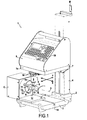
- the Fig. 1 is perspective of 3 ⁇ 4 face of a preferred embodiment of a marking device according to the invention.
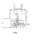
- the Fig. 2 is a partially exploded top view of the device shown in FIG. Fig. 1 .
- a marking device as schematically illustrated in FIG. Fig. 1 and generally designated by the reference 1 , comprises a support frame 2 which, according to the illustrated example, comprises a foot 3 on which is fixed a vertical bracket 4 supporting the marking system 5 and its control console 6 , mounted on a horizontal plate 7 .
- the plate 7 is advantageously secured by a nut or a nut of a worm integrated in the bracket 4 and manually operable by a crank M so that the plate 7 , and therefore the system of marking 5 and its control console are movable vertically on the vertical stem so as to adjust the position of the marking system 5 vis-à-vis an object O to mark.
- the marking system 4 is made in the form of an electromagnetic or other micro-percussion system comprising a marking member 8 , the end of which is intended to impact the surface S of an object O in order to carry out deformations therein. hollow or points of impact, as will appear later.
- the marking member 8 preferably comprises an electromagnetic coil, inside which is disposed a ferromagnetic core which acts on a marking tip 8 1 and which is movable in translation in the coil between a rest position and a position marking.
- the object O is placed between the jaws 11 of a mandrel 10 for supporting and rotating said object O around an axis of rotation D , said mandrel 10 being coupled to an electric drive motor arranged in a housing C being integral with the foot 3 of the device 1 by any appropriate means, and in particular in the example shown by means of a plate 12 fixed to the foot 3 in a sliding manner by tenons or screws 13 inserted in a T-slot 14 formed on the foot 3 .
- the marking system 5 comprises in addition, displacement means 15 , 16 , 17 , 18 of the marking member 8 .
- these displacement means comprise two translating guide rails 15 , 16 embodying perpendicular X and Y axes for translational guidance of the marking member 8 , which are connected to the plate 7 and therefore, by this means to the frame 2 .
- the rail 15 embodying the translational axis X of the marking member 8 , is parallel to the axis D of rotation of the object O on the yoke.
- the rail 16 materializing the Y axis of translation of the marking member 8 is perpendicular to the rail 15 and the axis D.
- the rail 16 forming the Y axis is fixed on the plate 7 .
- the rail 15 is movably mounted on the rail 16 by means of a motorized carriage 17 , comprising for example an electric motor step, allowing the translation of the carriage 17 along the rail 16 along the Y axis .
- the rail 15 carries the marking member 8 , which is carried on a second motorized carriage 18 , also for example equipped with an electric stepper motor, integral with the rail 15 .
- the amplitude of displacement of the marking member 8 along the guide rails 15 , 16 defines a marking window whose length is fixed by the amplitude of the translation along the X axis and whose width is determined by the amplitude of the translation along the Y axis. It is then possible, when starting the marking system 5 , to impact with the tip 8 1 of the marking member any point of the surface S of an object O located in the marking window.
- the motorized carriages 17 , 18 are advantageously powered and controlled by electronic control means integrated into the control console 6 .
- These control means comprise electronic means for feeding and driving the motorized carriages 17 , 18 for moving the marking head 8 on the rails 15 , 16 along the X , Y axes.
- These control means are generally called “motor driver Y” for controlling the motorized carriage 17 and “motor driver X” for controlling the carriage 18 .
- These "motor driver” X and Y are advantageously implemented directly on an electronic control board integrated in the control console and programmable by the user by means of a keyboard 19 on this console 6 .
- the electronic control means are also configured, in accordance with the present invention, for powering and driving the motor driving in rotation around the axis D of the mandrel 10 for supporting the object O to be marked.
- Such a rotation is sometimes necessary and advantageous for marking circular parts such as the part O represented on the figure 1 , to the extent that the rails 15 , 16 and motorized carriages 17 , 18 can only mobilize the marking member in a horizontal plane parallel to the axis of rotation D.
- the control of the drive motor of the mandrel 10 is not ensured by a dedicated motor driver but by the "motor driver Y" by shifting the power supply phases of the motorized carriage 17 towards the motor driving the mandrel 10 about the axis D.
- the electronic control means comprise bypass means, including relays, the supply of the carriage 17 for moving the member 8 on the axis 16 the drive motor of the mandrel 10 along the axis D.
- control electronics of the 3-axis marking device X , Y , D of the invention integrates only two commands of control axes, that is to say the X and Y motor drivers, the driver Y motor used to drive the driving motor of the mandrel 10 on the axis D.
- the electronic card therefore remains substantially identical to that of the so-called "2-axis" marking machines, which considerably reduces the cost of the marking device 1 of the invention compared with other known 3-axis machines.
- the motorized carriage 17 is locked in position at one end of the rail 15 mechanically by a magnet 20 secured to said carriage 17 and abutting against the front rim 7a of the support plate 7 of the marking system 5 .
- the magnet 20 is a permanent magnet sized so that the holding force is sufficient to blocking the carriage 17 in position during the marking of the rotating object on the axis D , but not too powerful for the motor torque of the motorized carriage 17 once the power supply of the latter restored after deactivating the motor D axis can after the marking release the magnet from the front edge of the plate to bring the carriage 17 and the marking member 8 to an original position.
- any other mechanical locking system of the member 8 on the rail 15 can also be envisaged without departing from the scope of the invention. It is also possible to block this position of the member 8 by injecting a holding current into the stepping motor of the motorized trolley 17 .
- the marking device of the invention and in particular the control means of the marking system, are thus constituted that at any time of a marking cycle of the surface S of an object O , the power supply of the motorized trolley of displacement of the marking member 8 along the Y axis can be switched to the drive motor of the mandrel 10 on the axis D and vice versa, to have similar functionality to a 3-axis machine and to mark circular parts without difficulty with a marking device 1 at a reduced cost.
- Power switching and control by electronic control between the motorized carriage 17 for moving the marking member 8 along the Y axis and the driving motor of the mandrel 10 along the axis D makes it possible to move on 3 axes. in the same marking cycle, for marking in grooves, for example, and to automatically return the marking member 8 to the original position at the end of the cycle thus clearing access to the object O once marked for the 'operator.
Landscapes
- Engineering & Computer Science (AREA)
- Mechanical Engineering (AREA)
- Permanent Magnet Type Synchronous Machine (AREA)
- Soil Working Implements (AREA)
- Control And Other Processes For Unpacking Of Materials (AREA)
- Toys (AREA)
- Details Or Accessories Of Spraying Plant Or Apparatus (AREA)
Claims (10)
- Vorrichtung (1) zum Markieren einer Fläche (S) eines Gegenstandes (O), umfassend:- ein Traggestell (2),- Markierungsmittel (5), die ein Markierungsorgan (8) umfassen, welches geeignet ist, einen Punkt oder eine im wesentlichen punktuelle Markierung herzustellen,- Mittel zum Bewegen (15, 16, 17, 18) des Markierungsorgans (8) in einem Markierungsfenster entlang von zwei Achsen (X, Y), die untereinander und zu der zu markierenden Fläche (S) senkrecht verlaufen, um auf der zu markierenden Fläche Zeichen zu erzeugen, wobei die Bewegungsmittel Antriebsmittel (17, 18) umfassen,- Mittel (10) zum Haltern und Drehbewegen des zu markierenden Gegenstandes (O) um eine Achse (D), die zu wenigstens einer der Achsen (X, Y) parallel verläuft, wobei die Mittel (10) zum Haltern und Bewegen des Gegentandes (O) wenigstens Antriebsmittel zum Drehantreiben um die Achse (D) umfassen,- automatische Mittel zum Steuern (6) der Mittel zum Bewegen des Markierungsorgans (8) und des zu markierenden Gegenstandes (O) entlang der Achsen (X, Y, D),dadurch gekennzeichnet, daß die automatischen Steuermittel (6) elektronische Mittel zur Versorgung und Steuerung der Antriebsmittel (17, 18) zum Bewegen entlang der Achsen (X, Y) sowie Mittel zum Abzweigen der Versorgung der Antriebsmittel zum Bewegen entlang der Achse (Y) zu den Antriebsmitteln zum Bewegen entlang der Achse (D) umfassen, so daß die Antriebsmittel zum Bewegen entlang der Achse (D) durch die Mittel zur Versorgung und Steuerung der Achse (Y) gesteuert werden.
- Markierungsvorrichtung nach Anspruch 1, dadurch gekennzeichnet, daß die Mittel zum Abzweigen der Versorgung der Antriebsmittel zum Bewegen entlang der Achse (Y) zu den Antriebsmitteln zum Bewegen entlang der Achse (D) elektronische Umschaltrelaissysteme umfassen.
- Markierungsvorrichtung nach Anspruch 1 oder 2, dadurch gekennzeichnet, daß sie Mittel zum Blockieren der Mittel zum Bewegen des Markierungskopfes entlang der Achse (Y) umfaßt.
- Markierungsvorrichtung nach Anspruch 3, dadurch gekennzeichnet, daß die Blockiermittel einen Permanentmagneten (20) umfassen, der geeignet ist, während der Versorgung der Antriebsmittel zum Bewegen entlang der Achse (D) die Mittel zum Bewegen des Markierungsorgans (8) senkrecht entlang der Achse (Y) zu blockieren.
- Markierungsvorrichtung nach Anspruch 3, dadurch gekennzeichnet, daß die Blockiermittel darin bestehen, daß durch die automatischen Steuermittel ein Haltestrom in die Antriebsmittel zum Bewegen entlang der Achse (Y) eingespeist wird.
- Markierungsvorrichtung nach einem der Ansprüche 1 bis 5, dadurch gekennzeichnet, daß die Mittel zum Bewegen des Markierungsorgans entlang der Achsen (X, Y) wenigstens ein Mittel (15) zur Verschiebeführung des Markierungsorgans entlang der Achse X parallel zu der zu markierenden Fläche (S) und wenigstens ein Mittel (16) zur Verschiebeführung des Markierungsorgans entlang der Achse Y senkrecht zur Achse X umfassen.
- Markierungsvorrichtung nach einem der Ansprüche 1 bis 6, dadurch gekennzeichnet, daß die Antriebsmittel zum Bewegen des Markierungsorgans (8) einen ersten motorisierten Schlitten (17) zur Verschiebebewegung des Markierungsorgans (8) entlang der Achse (Y) in beide Richtungen sowie einen zweiten motorisierten Schlitten (18) zur Verschiebebewegung des Markierungsorgans entlang der Achse (X) in beide Richtungen umfassen.
- Markierungsvorrichtung nach einem der Ansprüche 1 bis 7, dadurch gekennzeichnet, daß die Markierungsmittel (5) ein Mikroschlagsystem umfassen, welches das Markierungsorgan (8), das mit einer zwischen einer Ruhe- und einer Markierungsposition beweglichen Markierungsspitze (81) ausgestattet ist, umfaßt.
- Markierungsvorrichtung nach Anspruch 8, dadurch gekennzeichnet, daß das Mikroschlag-Markierungssystem (5) eine elektromagnetische Spule umfaßt, in der ein ferromagnetischer Kern angeordnet ist, der auf die Markierungsspitze wirkt und der in der Spule zwischen einer Ruhe- und einer Markierungsposition verschiebebeweglich ist.
- Markierungsvorrichtung nach Anspruch 8, dadurch gekennzeichnet, daß das Mikroschlag-Markierungssystem (5) ein pneumatisches System umfaßt, das auf die Markierungsspitze wirkt und das in der Spule zwischen einer Ruhe- und einer Markierungsposition verschiebebeweglich ist.
Applications Claiming Priority (2)
| Application Number | Priority Date | Filing Date | Title |
|---|---|---|---|
| FR0851489A FR2928288B1 (fr) | 2008-03-07 | 2008-03-07 | Machine de marquage |
| PCT/FR2009/050370 WO2009115745A2 (fr) | 2008-03-07 | 2009-03-06 | Machine de marquage |
Publications (2)
| Publication Number | Publication Date |
|---|---|
| EP2247404A2 EP2247404A2 (de) | 2010-11-10 |
| EP2247404B1 true EP2247404B1 (de) | 2012-01-04 |
Family
ID=39790337
Family Applications (1)
| Application Number | Title | Priority Date | Filing Date |
|---|---|---|---|
| EP09721665A Active EP2247404B1 (de) | 2008-03-07 | 2009-03-06 | Markierungsmaschine |
Country Status (5)
| Country | Link |
|---|---|
| EP (1) | EP2247404B1 (de) |
| AT (1) | ATE539842T1 (de) |
| ES (1) | ES2379512T3 (de) |
| FR (1) | FR2928288B1 (de) |
| WO (1) | WO2009115745A2 (de) |
Families Citing this family (3)
| Publication number | Priority date | Publication date | Assignee | Title |
|---|---|---|---|---|
| CN103522812A (zh) * | 2013-10-25 | 2014-01-22 | 安庆市宏大涛业精啄数控科技有限公司 | 整体上下型数控边雕机 |
| FR3024674B1 (fr) * | 2014-08-08 | 2016-08-26 | Sic Marking Group | Appareil portatif pour le marquage d'une surface |
| CN104943398B (zh) * | 2015-06-30 | 2016-07-06 | 北京恒博山科技发展有限责任公司 | 一种手持式电磁打标机 |
Family Cites Families (2)
| Publication number | Priority date | Publication date | Assignee | Title |
|---|---|---|---|---|
| FR2555086B1 (fr) * | 1983-11-17 | 1987-12-11 | Cottin Jean Claude | Morphologie de construction d'une machine-outil d'usinage multifonctionnelle pour tournage, fraisage, percage, alesage, taraudage avec un ou deux outils actifs simultanement |
| EP1700653A1 (de) * | 2005-03-11 | 2006-09-13 | ANNN Yang Machinery Co., Ltd. | Vertikal Dreh-, Fräsmaschine |
-
2008
- 2008-03-07 FR FR0851489A patent/FR2928288B1/fr not_active Expired - Fee Related
-
2009
- 2009-03-06 WO PCT/FR2009/050370 patent/WO2009115745A2/fr not_active Ceased
- 2009-03-06 AT AT09721665T patent/ATE539842T1/de active
- 2009-03-06 EP EP09721665A patent/EP2247404B1/de active Active
- 2009-03-06 ES ES09721665T patent/ES2379512T3/es active Active
Also Published As
| Publication number | Publication date |
|---|---|
| ES2379512T3 (es) | 2012-04-26 |
| FR2928288A1 (fr) | 2009-09-11 |
| FR2928288B1 (fr) | 2010-05-28 |
| WO2009115745A3 (fr) | 2009-11-12 |
| EP2247404A2 (de) | 2010-11-10 |
| ATE539842T1 (de) | 2012-01-15 |
| WO2009115745A2 (fr) | 2009-09-24 |
Similar Documents
| Publication | Publication Date | Title |
|---|---|---|
| EP2247404B1 (de) | Markierungsmaschine | |
| EP0371896A1 (de) | Mikroschlaggerät für Markierung | |
| CH656082A5 (fr) | Machine pour decoupage par electroerosion avec immobilisation de la chute. | |
| FR2582564A1 (fr) | Dispositif de coupe a lame rotative pour le decoupage d'un materiau en feuille, comportant un dispositif d'aiguisage | |
| EP1605242B1 (de) | System zur Benutzung einer Vorrichtung zum Entnehmen einer Probe aus dem Grund oder eines körnigen oder pulverförmigen Materials | |
| EP1820647B1 (de) | Maschine und Verfahren zum Markieren von Formteilen | |
| FR2676947A1 (fr) | Machine de decoupage de toles et de tubes a commande numerique. | |
| EP1401746B1 (de) | Vorrichtung zum zuführen von teilen zu einer maschine | |
| EP1809488B1 (de) | Markierungsvorrichtung | |
| EP0281488A1 (de) | Drehender Biegekopf für Rohrbiegemaschine | |
| JP4237365B2 (ja) | 圧延用ガイド装置におけるレストバー装置 | |
| EP0069041B1 (de) | Umblättergerät | |
| EP0084504B1 (de) | Apparat zum Schleifen von Glaskanten | |
| EP3967465A1 (de) | Brotschneidemaschine mit einer halterung für die brotscheiben | |
| JP2001038719A (ja) | 石材切断機 | |
| FR2744143A1 (fr) | Meuleuse de rails | |
| EP0237690A1 (de) | Verschiebbarer Druckkopf | |
| FR2823029A1 (fr) | Pince motorisee pour le bridage d'elements allonges | |
| EP0226547A2 (de) | Vorrichtung zum Steuern einer Verlegeoperation | |
| FR2915410A1 (fr) | Machine a cintrer un profile selon deux sens de cintrage. | |
| FR2806945A1 (fr) | Centre de poinconnage, destine notamment au poinconnage de toles | |
| FR2481634A1 (fr) | Dispositif de serrage pour machine a meuler et/ou biseauter des verres de lunettes; machine equipee de ce dispositif | |
| FR2898535A1 (fr) | Dispositif de marquage a moteurs mobiles | |
| EP0081614B1 (de) | Siebdruckmaschine mit einer von einem Elektromagnet betätigten Vorrichtung zum Absenken der Rakel | |
| EP1595614A1 (de) | Stanzmaschine |
Legal Events
| Date | Code | Title | Description |
|---|---|---|---|
| PUAI | Public reference made under article 153(3) epc to a published international application that has entered the european phase |
Free format text: ORIGINAL CODE: 0009012 |
|
| 17P | Request for examination filed |
Effective date: 20100805 |
|
| AK | Designated contracting states |
Kind code of ref document: A2 Designated state(s): AT BE BG CH CY CZ DE DK EE ES FI FR GB GR HR HU IE IS IT LI LT LU LV MC MK MT NL NO PL PT RO SE SI SK TR |
|
| AX | Request for extension of the european patent |
Extension state: AL BA RS |
|
| DAX | Request for extension of the european patent (deleted) | ||
| GRAP | Despatch of communication of intention to grant a patent |
Free format text: ORIGINAL CODE: EPIDOSNIGR1 |
|
| GRAS | Grant fee paid |
Free format text: ORIGINAL CODE: EPIDOSNIGR3 |
|
| GRAA | (expected) grant |
Free format text: ORIGINAL CODE: 0009210 |
|
| AK | Designated contracting states |
Kind code of ref document: B1 Designated state(s): AT BE BG CH CY CZ DE DK EE ES FI FR GB GR HR HU IE IS IT LI LT LU LV MC MK MT NL NO PL PT RO SE SI SK TR |
|
| REG | Reference to a national code |
Ref country code: GB Ref legal event code: FG4D Free format text: NOT ENGLISH |
|
| REG | Reference to a national code |
Ref country code: CH Ref legal event code: EP |
|
| REG | Reference to a national code |
Ref country code: AT Ref legal event code: REF Ref document number: 539842 Country of ref document: AT Kind code of ref document: T Effective date: 20120115 |
|
| REG | Reference to a national code |
Ref country code: IE Ref legal event code: FG4D |
|
| REG | Reference to a national code |
Ref country code: DE Ref legal event code: R096 Ref document number: 602009004546 Country of ref document: DE Effective date: 20120301 |
|
| REG | Reference to a national code |
Ref country code: ES Ref legal event code: FG2A Ref document number: 2379512 Country of ref document: ES Kind code of ref document: T3 Effective date: 20120426 |
|
| REG | Reference to a national code |
Ref country code: NL Ref legal event code: VDEP Effective date: 20120104 |
|
| PG25 | Lapsed in a contracting state [announced via postgrant information from national office to epo] |
Ref country code: SI Free format text: LAPSE BECAUSE OF FAILURE TO SUBMIT A TRANSLATION OF THE DESCRIPTION OR TO PAY THE FEE WITHIN THE PRESCRIBED TIME-LIMIT Effective date: 20120104 |
|
| LTIE | Lt: invalidation of european patent or patent extension |
Effective date: 20120104 |
|
| PG25 | Lapsed in a contracting state [announced via postgrant information from national office to epo] |
Ref country code: HR Free format text: LAPSE BECAUSE OF FAILURE TO SUBMIT A TRANSLATION OF THE DESCRIPTION OR TO PAY THE FEE WITHIN THE PRESCRIBED TIME-LIMIT Effective date: 20120104 Ref country code: NL Free format text: LAPSE BECAUSE OF FAILURE TO SUBMIT A TRANSLATION OF THE DESCRIPTION OR TO PAY THE FEE WITHIN THE PRESCRIBED TIME-LIMIT Effective date: 20120104 Ref country code: BG Free format text: LAPSE BECAUSE OF FAILURE TO SUBMIT A TRANSLATION OF THE DESCRIPTION OR TO PAY THE FEE WITHIN THE PRESCRIBED TIME-LIMIT Effective date: 20120404 Ref country code: LT Free format text: LAPSE BECAUSE OF FAILURE TO SUBMIT A TRANSLATION OF THE DESCRIPTION OR TO PAY THE FEE WITHIN THE PRESCRIBED TIME-LIMIT Effective date: 20120104 Ref country code: NO Free format text: LAPSE BECAUSE OF FAILURE TO SUBMIT A TRANSLATION OF THE DESCRIPTION OR TO PAY THE FEE WITHIN THE PRESCRIBED TIME-LIMIT Effective date: 20120404 Ref country code: IS Free format text: LAPSE BECAUSE OF FAILURE TO SUBMIT A TRANSLATION OF THE DESCRIPTION OR TO PAY THE FEE WITHIN THE PRESCRIBED TIME-LIMIT Effective date: 20120504 |
|
| REG | Reference to a national code |
Ref country code: IE Ref legal event code: FD4D |
|
| PG25 | Lapsed in a contracting state [announced via postgrant information from national office to epo] |
Ref country code: LV Free format text: LAPSE BECAUSE OF FAILURE TO SUBMIT A TRANSLATION OF THE DESCRIPTION OR TO PAY THE FEE WITHIN THE PRESCRIBED TIME-LIMIT Effective date: 20120104 Ref country code: PL Free format text: LAPSE BECAUSE OF FAILURE TO SUBMIT A TRANSLATION OF THE DESCRIPTION OR TO PAY THE FEE WITHIN THE PRESCRIBED TIME-LIMIT Effective date: 20120104 Ref country code: FI Free format text: LAPSE BECAUSE OF FAILURE TO SUBMIT A TRANSLATION OF THE DESCRIPTION OR TO PAY THE FEE WITHIN THE PRESCRIBED TIME-LIMIT Effective date: 20120104 Ref country code: PT Free format text: LAPSE BECAUSE OF FAILURE TO SUBMIT A TRANSLATION OF THE DESCRIPTION OR TO PAY THE FEE WITHIN THE PRESCRIBED TIME-LIMIT Effective date: 20120504 Ref country code: GR Free format text: LAPSE BECAUSE OF FAILURE TO SUBMIT A TRANSLATION OF THE DESCRIPTION OR TO PAY THE FEE WITHIN THE PRESCRIBED TIME-LIMIT Effective date: 20120405 |
|
| REG | Reference to a national code |
Ref country code: AT Ref legal event code: MK05 Ref document number: 539842 Country of ref document: AT Kind code of ref document: T Effective date: 20120104 |
|
| PG25 | Lapsed in a contracting state [announced via postgrant information from national office to epo] |
Ref country code: CY Free format text: LAPSE BECAUSE OF FAILURE TO SUBMIT A TRANSLATION OF THE DESCRIPTION OR TO PAY THE FEE WITHIN THE PRESCRIBED TIME-LIMIT Effective date: 20120104 |
|
| BERE | Be: lapsed |
Owner name: SIC MARKING HOLDING - SMH Effective date: 20120331 |
|
| PG25 | Lapsed in a contracting state [announced via postgrant information from national office to epo] |
Ref country code: DK Free format text: LAPSE BECAUSE OF FAILURE TO SUBMIT A TRANSLATION OF THE DESCRIPTION OR TO PAY THE FEE WITHIN THE PRESCRIBED TIME-LIMIT Effective date: 20120104 Ref country code: MC Free format text: LAPSE BECAUSE OF NON-PAYMENT OF DUE FEES Effective date: 20120331 Ref country code: EE Free format text: LAPSE BECAUSE OF FAILURE TO SUBMIT A TRANSLATION OF THE DESCRIPTION OR TO PAY THE FEE WITHIN THE PRESCRIBED TIME-LIMIT Effective date: 20120104 Ref country code: RO Free format text: LAPSE BECAUSE OF FAILURE TO SUBMIT A TRANSLATION OF THE DESCRIPTION OR TO PAY THE FEE WITHIN THE PRESCRIBED TIME-LIMIT Effective date: 20120104 Ref country code: CZ Free format text: LAPSE BECAUSE OF FAILURE TO SUBMIT A TRANSLATION OF THE DESCRIPTION OR TO PAY THE FEE WITHIN THE PRESCRIBED TIME-LIMIT Effective date: 20120104 Ref country code: IE Free format text: LAPSE BECAUSE OF FAILURE TO SUBMIT A TRANSLATION OF THE DESCRIPTION OR TO PAY THE FEE WITHIN THE PRESCRIBED TIME-LIMIT Effective date: 20120104 Ref country code: SE Free format text: LAPSE BECAUSE OF FAILURE TO SUBMIT A TRANSLATION OF THE DESCRIPTION OR TO PAY THE FEE WITHIN THE PRESCRIBED TIME-LIMIT Effective date: 20120104 |
|
| PLBE | No opposition filed within time limit |
Free format text: ORIGINAL CODE: 0009261 |
|
| STAA | Information on the status of an ep patent application or granted ep patent |
Free format text: STATUS: NO OPPOSITION FILED WITHIN TIME LIMIT |
|
| PG25 | Lapsed in a contracting state [announced via postgrant information from national office to epo] |
Ref country code: SK Free format text: LAPSE BECAUSE OF FAILURE TO SUBMIT A TRANSLATION OF THE DESCRIPTION OR TO PAY THE FEE WITHIN THE PRESCRIBED TIME-LIMIT Effective date: 20120104 |
|
| 26N | No opposition filed |
Effective date: 20121005 |
|
| PG25 | Lapsed in a contracting state [announced via postgrant information from national office to epo] |
Ref country code: BE Free format text: LAPSE BECAUSE OF NON-PAYMENT OF DUE FEES Effective date: 20120331 Ref country code: AT Free format text: LAPSE BECAUSE OF FAILURE TO SUBMIT A TRANSLATION OF THE DESCRIPTION OR TO PAY THE FEE WITHIN THE PRESCRIBED TIME-LIMIT Effective date: 20120104 |
|
| REG | Reference to a national code |
Ref country code: DE Ref legal event code: R097 Ref document number: 602009004546 Country of ref document: DE Effective date: 20121005 |
|
| PG25 | Lapsed in a contracting state [announced via postgrant information from national office to epo] |
Ref country code: MK Free format text: LAPSE BECAUSE OF FAILURE TO SUBMIT A TRANSLATION OF THE DESCRIPTION OR TO PAY THE FEE WITHIN THE PRESCRIBED TIME-LIMIT Effective date: 20120104 |
|
| PG25 | Lapsed in a contracting state [announced via postgrant information from national office to epo] |
Ref country code: MT Free format text: LAPSE BECAUSE OF FAILURE TO SUBMIT A TRANSLATION OF THE DESCRIPTION OR TO PAY THE FEE WITHIN THE PRESCRIBED TIME-LIMIT Effective date: 20120104 |
|
| REG | Reference to a national code |
Ref country code: CH Ref legal event code: PL |
|
| PG25 | Lapsed in a contracting state [announced via postgrant information from national office to epo] |
Ref country code: CH Free format text: LAPSE BECAUSE OF NON-PAYMENT OF DUE FEES Effective date: 20130331 Ref country code: LI Free format text: LAPSE BECAUSE OF NON-PAYMENT OF DUE FEES Effective date: 20130331 |
|
| PG25 | Lapsed in a contracting state [announced via postgrant information from national office to epo] |
Ref country code: TR Free format text: LAPSE BECAUSE OF FAILURE TO SUBMIT A TRANSLATION OF THE DESCRIPTION OR TO PAY THE FEE WITHIN THE PRESCRIBED TIME-LIMIT Effective date: 20120104 |
|
| PG25 | Lapsed in a contracting state [announced via postgrant information from national office to epo] |
Ref country code: LU Free format text: LAPSE BECAUSE OF NON-PAYMENT OF DUE FEES Effective date: 20120306 |
|
| PG25 | Lapsed in a contracting state [announced via postgrant information from national office to epo] |
Ref country code: HU Free format text: LAPSE BECAUSE OF FAILURE TO SUBMIT A TRANSLATION OF THE DESCRIPTION OR TO PAY THE FEE WITHIN THE PRESCRIBED TIME-LIMIT Effective date: 20090306 |
|
| PGFP | Annual fee paid to national office [announced via postgrant information from national office to epo] |
Ref country code: IT Payment date: 20150325 Year of fee payment: 7 Ref country code: DE Payment date: 20150311 Year of fee payment: 7 Ref country code: ES Payment date: 20150324 Year of fee payment: 7 |
|
| PGFP | Annual fee paid to national office [announced via postgrant information from national office to epo] |
Ref country code: GB Payment date: 20150316 Year of fee payment: 7 |
|
| REG | Reference to a national code |
Ref country code: FR Ref legal event code: PLFP Year of fee payment: 8 |
|
| REG | Reference to a national code |
Ref country code: DE Ref legal event code: R119 Ref document number: 602009004546 Country of ref document: DE |
|
| GBPC | Gb: european patent ceased through non-payment of renewal fee |
Effective date: 20160306 |
|
| REG | Reference to a national code |
Ref country code: FR Ref legal event code: PLFP Year of fee payment: 9 |
|
| PG25 | Lapsed in a contracting state [announced via postgrant information from national office to epo] |
Ref country code: GB Free format text: LAPSE BECAUSE OF NON-PAYMENT OF DUE FEES Effective date: 20160306 Ref country code: DE Free format text: LAPSE BECAUSE OF NON-PAYMENT OF DUE FEES Effective date: 20161001 |
|
| PG25 | Lapsed in a contracting state [announced via postgrant information from national office to epo] |
Ref country code: IT Free format text: LAPSE BECAUSE OF NON-PAYMENT OF DUE FEES Effective date: 20160306 |
|
| REG | Reference to a national code |
Ref country code: FR Ref legal event code: PLFP Year of fee payment: 10 |
|
| PG25 | Lapsed in a contracting state [announced via postgrant information from national office to epo] |
Ref country code: ES Free format text: LAPSE BECAUSE OF NON-PAYMENT OF DUE FEES Effective date: 20160307 |
|
| REG | Reference to a national code |
Ref country code: ES Ref legal event code: FD2A Effective date: 20180625 |
|
| PGFP | Annual fee paid to national office [announced via postgrant information from national office to epo] |
Ref country code: FR Payment date: 20251215 Year of fee payment: 18 |