EP2247406B1 - Bohrkopf mit kardanscharnier - Google Patents
Bohrkopf mit kardanscharnier Download PDFInfo
- Publication number
- EP2247406B1 EP2247406B1 EP09716511A EP09716511A EP2247406B1 EP 2247406 B1 EP2247406 B1 EP 2247406B1 EP 09716511 A EP09716511 A EP 09716511A EP 09716511 A EP09716511 A EP 09716511A EP 2247406 B1 EP2247406 B1 EP 2247406B1
- Authority
- EP
- European Patent Office
- Prior art keywords
- axis
- pin
- machine tool
- milling head
- tool according
- Prior art date
- Legal status (The legal status is an assumption and is not a legal conclusion. Google has not performed a legal analysis and makes no representation as to the accuracy of the status listed.)
- Active
Links
Images


Classifications
-
- B—PERFORMING OPERATIONS; TRANSPORTING
- B23—MACHINE TOOLS; METAL-WORKING NOT OTHERWISE PROVIDED FOR
- B23Q—DETAILS, COMPONENTS, OR ACCESSORIES FOR MACHINE TOOLS, e.g. ARRANGEMENTS FOR COPYING OR CONTROLLING; MACHINE TOOLS IN GENERAL CHARACTERISED BY THE CONSTRUCTION OF PARTICULAR DETAILS OR COMPONENTS; COMBINATIONS OR ASSOCIATIONS OF METAL-WORKING MACHINES, NOT DIRECTED TO A PARTICULAR RESULT
- B23Q1/00—Members which are comprised in the general build-up of a form of machine, particularly relatively large fixed members
- B23Q1/25—Movable or adjustable work or tool supports
- B23Q1/44—Movable or adjustable work or tool supports using particular mechanisms
- B23Q1/50—Movable or adjustable work or tool supports using particular mechanisms with rotating pairs only, the rotating pairs being the first two elements of the mechanism
- B23Q1/54—Movable or adjustable work or tool supports using particular mechanisms with rotating pairs only, the rotating pairs being the first two elements of the mechanism two rotating pairs only
- B23Q1/5406—Movable or adjustable work or tool supports using particular mechanisms with rotating pairs only, the rotating pairs being the first two elements of the mechanism two rotating pairs only a single rotating pair followed perpendicularly by a single rotating pair
-
- B—PERFORMING OPERATIONS; TRANSPORTING
- B23—MACHINE TOOLS; METAL-WORKING NOT OTHERWISE PROVIDED FOR
- B23C—MILLING
- B23C1/00—Milling machines not designed for particular work or special operations
- B23C1/002—Gantry-type milling machines
-
- B—PERFORMING OPERATIONS; TRANSPORTING
- B23—MACHINE TOOLS; METAL-WORKING NOT OTHERWISE PROVIDED FOR
- B23C—MILLING
- B23C1/00—Milling machines not designed for particular work or special operations
- B23C1/12—Milling machines not designed for particular work or special operations with spindle adjustable to different angles, e.g. either horizontal or vertical
-
- B—PERFORMING OPERATIONS; TRANSPORTING
- B23—MACHINE TOOLS; METAL-WORKING NOT OTHERWISE PROVIDED FOR
- B23C—MILLING
- B23C9/00—Details or accessories so far as specially adapted to milling machines or cutter
- B23C9/005—Details or accessories so far as specially adapted to milling machines or cutter milling heads
-
- B—PERFORMING OPERATIONS; TRANSPORTING
- B23—MACHINE TOOLS; METAL-WORKING NOT OTHERWISE PROVIDED FOR
- B23Q—DETAILS, COMPONENTS, OR ACCESSORIES FOR MACHINE TOOLS, e.g. ARRANGEMENTS FOR COPYING OR CONTROLLING; MACHINE TOOLS IN GENERAL CHARACTERISED BY THE CONSTRUCTION OF PARTICULAR DETAILS OR COMPONENTS; COMBINATIONS OR ASSOCIATIONS OF METAL-WORKING MACHINES, NOT DIRECTED TO A PARTICULAR RESULT
- B23Q2220/00—Machine tool components
- B23Q2220/006—Spindle heads
Definitions
- the present invention relates to a machine tool of the five-axis machining machine type for metals or composite materials.
- a machining machine is generally provided so that the combination of displacements in translation or in rotation of its various members makes it possible to position the machining tool at any point of a reference reference linked to the workpiece. , and to orient the rotary axis of this tool in any direction of this marker in order to achieve the desired result.
- the French patent application no. 2,552,002 discloses a milling device comprising a main body mounted on a milling head carrying a machining spindle and capable of occupying several indexing positions with respect to said head by pivoting about the vertical rotary axis conventionally called C located in the extension of the axis of the spindle of the milling head, said main body laterally carrying a spindle unit capable of occupying several indexing positions with respect to the main body by pivoting about the axis of pivoting horizontally conventionally called B perpendicular to the rotary axis C, the spindle of the spindle unit being itself perpendicular to the pivot axis B.
- the lateral position of the spindle unit results in a particularly bulky end of the milling device which generally allows only surface machining of the objects to be machined.
- a machining machine must allow the machining of left curvilinear surfaces as well as machining inside the volume of the workpiece, requiring that the milling head can penetrate and rotate in the same volume without causing machine-room interference.
- the milling head must be able to dive into the workpiece volume while stepping over but avoiding contact with any protruding parts of material that need not be machined.
- the machining machines usually comprise a milling head rotatably driven and having one or more joints, mounted on one end of a vertical or horizontal support movable in the three directions, namely along the linear axes X, Y, Z known to those skilled in the art.
- the machining machines comprise a multi-axis swivel milling head comprising a movable fork-unit pivotally mounted around the vertical rotary axis C , a support shaft rotatably mounted in the fork unit about the horizontal pivot axis B orthogonal to C and at least one pin mounted on the support shaft and horizontal pivot axis A orthogonal to B and C.
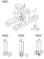
- a machining machine of this type is shown schematically on the figure 3 .
- milling machines In order to allow more possibilities of movements of the milling spindle, in addition to pivoting about the horizontal pivot axis B, recent milling machines comprise a milling head whose spindle unit allows pivoting additional spindle along the horizontal pivot axis A orthogonal to B and C, the axis A being offset in space with respect to the horizontal pivot axis B so that the pivot axes A and B do not do not cut.
- a milling machine said head without C because it does not pivot around the vertical rotary axis C, is shown schematically on the figure 4 .
- the new milling heads can combine pivoting on both the A and B axes, the fact that these two axes do not intersect usually results in limited travel for the spindle nose. and also results in a much more complicated control of the machine because the spindle offset must be taken into account, that is to say the shift in the X direction between the axis A and the axis C. Indeed With these milling heads, the machine must take into account two offset shifts, namely the offset between the axis A and the spindle nose, and the offset between the axis B and the spindle nose.
- the milling head of the machine tool comprises pivoting means along the horizontal pivot axes A and B so that the pivot axes A and B intersect at 90 °, this which offers a large angular movement for the spindle unit.
- the milling head according to the invention which comprises a spindle unit comprising a milling spindle, is pivotally articulated on a Z-axis runner at one end of a movable support along the three linear axes.
- X, Y, Z by means of a hinge member and pivotal orientation.
- This hinge and pivoting element comprises a central core having two horizontal pivot axes A and B which intersect at 90 °, respectively associated with the linear axes X and Y, one ensuring the connection with the flowing duct.
- Z axis and the other with the spindle unit is pivotally articulated on a Z-axis runner at one end of a movable support along the three linear axes.
- X, Y, Z by means of a hinge member and pivotal orientation.
- This hinge and pivoting element comprises a central core having two horizontal pivot axes A and B which intersect at 90 °, respectively associated with the linear axes X and Y, one ensuring the connection with the flowing
- the articulating element and pivoting orientation is of a design that is close to an operation inspired by a cardan movement.
- the motorization of the pivoting orientation of the milling head is made possible by the use of torque motors and / or servomotors combined with a new type of planetary speed reducer. Indeed, this use allows a servocontrol of the axis with sufficient precision and power for machining metals such as aluminum or different composite materials.
- the milling head according to the invention allows a free movement of the spindle nose in a volume at least equal to a half-sphere, which is very much greater than the travel limits of some previous milling heads whose pivoting is often limited to +/- 65 °.
- the milling head 1 according to the invention is mounted on a coulant 2 designated Z axis.
- the Z-axis runner 2 can be horizontal as well as vertical and that the milling head 1 of the invention is provided to be mounted on the free end thereof, for example at the bottom of the latter. ci if the flowing 2 Z axis is vertical.
- This duct 2 is preferably designed to be mounted on one end 3 of a vertical or horizontal support 4 movable in the three directions, namely along the linear axes X, Y, Z, as known to those skilled in the art, for example on a mobile gantry 4 as shown schematically on the figure 1 .
- the linear guidance of the Z axis is extended downwards in a first pair of lateral cheeks 5, 6 in order to stiffen the structure, these cheeks 5, 6 preferably being integral with the flow 2 of the Z axis.
- a bore , or other means of pivoting, passing through the two flanges 5, 6 of the Z-axis flange is designated axis B.
- a spindle unit 8 preferably of substantially conical shape, comprises a milling spindle 9 at one of its ends, for example at the spindle nose 10, or the spike in the advantageously conical shape of the door unit. -brooch.
- the advantageously conical shape of the spindle unit 8 is known to those skilled in the art. provides a minimal bulk around the milling spindle 9 while reducing the overall weight of the spindle unit 8, which translates into the proportional needs of the torque force of the drives for the drive ensuring the movements of the spindle. milling head 1.
- the conical-shaped spindle unit 8 further has various bores 11 distributed evenly around its periphery to provide additional weight gain.
- the spindle unit 8 is extended, preferably upwards, in a second pair of lateral cheeks 13, 14, these cheeks 13, 14 being preferably monoblock with the spindle unit 8 So, as can be noticed on the Figures 5 and 6 the spindle unit 8 is fork-shaped.
- a bore, or other means of pivoting, passing through the two cheeks 13, 14 of the spindle unit 8 is designated pivot axis A.
- the central core 7 is also pivotally mounted about the axis A between the flanges 13, 14 of the spindle unit 8. Thus, the central core 7 ensures the mechanical connection between the axis A and the axis B .
- the pivot axis A intersects the pivot axis B at 90 ° substantially in the middle of the central core 7 and at a substantially equal distance between the two flanges 5, 6 of the Z-axis flange 2 .
- the axes A and B operate in the manner of a cardan whose center is constituted by the central core 7.
- the milling head 1 makes it possible to combine pivoting on both axis A and axis B, which provides a large angular movement for the spindle unit 8.
- the pivoting stroke of the axis A and of the axis B is advantageously at least +/- 90 °.
- the drive of the axis B is preferably shifted into the cheeks 5, 6 of the Z axis flange 2, while the drive of the axis A is substantially housed. in the central core 7.
- the preferred embodiment of the invention is particularly represented on the Figures 7 to 11 , which are particularly interested in guiding and motorization for driving the milling head 1.
- the driving of the axis B is preferably at least partially housed in the cheeks 5, 6 (not shown in this figure) of the Z-axis sliding 2 and in the lower part thereof.
- Two motors 15, 16 are housed in the Z axis flange 2, the output shafts 17, 18 of which are connected to the same rotary shaft 19 of the central core 7 along the axis B.
- This kinematic connection is preferably made by a belt 20, 21, a chain, a series of gears or the like.
- each motor 15, 16 housed in the duct 2 is respectively connected to a different end 22, 23 of the rotary shaft 19 of the central core 7 along the axis B, these two ends 22, 23 being opposite from each other. other of the central nucleus 7.
- These two opposite ends 22, 23 are preferably mounted each rotatably in a respective pulley 24, 25, each of these pulleys 24, 25 being mounted in a respective bearing 26, 27 to ensure the guidance of the drive of the head Milling 1 along the axis B and cancel any potential axiality fault.
- At least one of these respective bearings 26, 27 is preferably a precision bearing for combined loads, for example of the type manufactured by INA FAG under the trade name YRTM.
- These bearings, hereinafter referred to as "YRTM bearings" comprise two integrated positioning measurement sensors, based on the displacement of a surface comprising a magnetic tape in front of a sensor. The coexistence of two sensors allows operational safety in case of failure of one of the sensors.
- the YRTM bearings 26, 27 thus also make it possible to measure angular positioning of the milling head 1 along the axis B.
- the person skilled in the art may, however, use any other known device making it possible to carry out such an operation. measured.
- the diameter of the rotary shaft 19 of the central core 7 along the axis B will be chosen by those skilled in the art as a function of the desired power and speed for the pivoting of the milling head 1 around the axis B .
- a speed reducer housed in the flanges 5, 6 of the duct 2 can be kinematically connected between each of the motors 15, 16 housed in the duct 2 and the rotary shaft 19 of the central core 7 according to FIG. axis B.
- the drive of the axis A is preferably at least partially housed in the central core 7 and in the cheeks 13, 14 (not shown in this figure) of the spindle unit 8.
- This drive of the axis A preferably comprises a drive unit 28 which is housed in the central core 7 and kinematically connected to at least one, preferably two speed reducing units 29, 30 which are housed in the cheeks 13, 14 of the spindle unit 8.
- the drive unit 28 comprises two substantially symmetrical motors 31, 32, mounted back-to-back in the central core 7 and integral therewith. It is preferentially torque motors 31, 32 which have the particular advantage of being very compact compared to other conventional electric motors.
- each of these torque motors 31, 32 is connected to one of the gear reduction units 29, 30 housed in the flanges 13, 14 of the spindle unit 8.
- each of these speed reducing units 29, 30 comprises a first gearbox 35, 36, for example of the planetary speed reducer type, and a second gearbox 37, 38, for example of the kinematic type of stepped gears.
- the first gear 35, 36 is mounted inside a bearing 39, 40, preferably YRTM type, this bearing 39, 40 being rotatably mounted in a fixed part 41 , 42 secured to the spindle unit 8.
- This bearing 39, 40 preferably ensures the centering of the first gear 35, 36 and the axis A on the central core 7.
- the satellites 43 and 44, 45 and 46 of the second gear 37, 38 are mounted preferentially preloaded in a fixed part 41, 42 integral with the spindle unit 8.
- the precharging of the second gear 37, 38 makes it possible to cancel the clearance and any axial error of the pin 9, and thus the pivoting of the spindle unit 8 along the axis A is perfectly centered with respect to the central core 7.
- the fixed parts 41, 42 integral with the spindle unit 8 and on which are mounted the various bearings 39, 40 are preferably the cheeks 13, 14 or a fixed pinion 41, 42 integral (s) of the housing 47 of the spindle unit 8.
- a movable sleeve 48 designated W axis and supporting the pin 9 is also mounted in the spindle unit 8 in the axis of the spindle nose 10. This advantageously allows the pin 9 to be moved. along the axis W, for example to make holes that are then much easier and more accurate than if they were made by an overall displacement of the milling head 1 which would result from an equivalent displacement of the spindle nose 10 .
- the movable sheath 48 along the axis W is preferably guided by two guide bearings 49 and 50, for example bronze, each comprising a locking means, preferably hydraulic (not shown).
- This hydraulic locking means of the movable sheath 48 makes it possible to block the milling spindle 9 in position along the axis W when the latter is in position to rotate.
- the movable sleeve 48 supporting the milling spindle 9 is unlocked.
- Each hydraulic locking means of the mobile sleeve 48 is for example made in a manner known to those skilled in the art by means of a pressurized fluid deforming a thin wall of the guide bearings 49 and 50 located against the mobile sheath 48 supporting the pin 9.
- the drive of the mobile sleeve 48 along the axis W is preferably carried out by one or more ball screws 51, 52.
- the movable sheath 48 is driven along the axis W by two ball screws 51, 52. Nevertheless, those skilled in the art will adapt the number of ball screws to be used as a function of the weight of the electric spindle.
- Each ball screw 51, 52 is preferably rotatably mounted between two fixed bearings 53 and 54, 55 and 56 themselves mounted integral with the spindle unit 8.
- a ball screw nut 57, 58 is mounted on each ball screw 51, 52, each nut 57, 58 being connected to the body of the movable sleeve 48 via a respective transverse arm 59, 60.
- the linear stroke of the movable sheath 48, and thus the spindle nose 10, along the axis W is about 100 mm.
- This type of drive for the spindle nose 10 along the axis W is in particular inexpensive, robust, precise and makes it possible to index the position accurately.
- those skilled in the art can easily adapt any other type of drive for the spindle nose 10, which is particularly easy because the greater part of the volume of the spindle
- the spindle unit 8 preferably does not include any of the actuators intended for pivoting the axis A and the axis B.
- This locking means preferably hydraulic, can be of any type known to those skilled in the art.
Landscapes
- Engineering & Computer Science (AREA)
- Mechanical Engineering (AREA)
- Machine Tool Units (AREA)
- Drilling And Boring (AREA)
- Magnetic Heads (AREA)
Claims (13)
- Werkzeugmaschine vom Typ Bearbeitungsmaschine mit fünf Achsen für Metalle oder Verbundmaterialien mit einem Träger (4), der auf den drei linearen Achsen X, Y, Z beweglich ist, und mit einem drehbaren mehrachsigen Fräskopf (1), der auf einen Schieber (2) der Z-Achse des Trägers (4) der Werkzeugmaschine montiert ist, besagter Fräskopf (1) folgende Elemente aufweist:• eine Spindelträgereinheit (8) mit einer Frässpindel (9) an einem ihrer Enden auf Höhe einer Spindelnase (10), und• ein Gelenk- und Ausrichtungselement zur drehbaren Lagerung des Fräskopfs (1) auf dem Schieber (2) der Z-Achse, wobei die Werkzeugmaschine dadurch gekennzeichnet ist, dass:• das Gelenk- und Ausrichtungselement vom Typ Kardanwelle zwei waagrechte Drehachsen A und B aufweist, die sich im 90°-Winkel schneiden, verbunden mit der linearen X- bzw. Y-Achse, wobei die eine die Verbindung mit dem Schieber (2) der Z-Achse sichert und die andere die mit der Spindelträgereinheit (8); sowie dadurch, dass• auf Höhe ihres Endes (12), das nicht die Spindelträgereinheit (8) umfasst, der Schieber (2) der Z-Achse ein erstes Paar Seitenwangen (5, 6) umfasst;• auf Höhe ihres Endes (12), das nicht die Frässpindel (9) umfasst, die Spindelträgereinheit (8) ein zweites Paar Seitenwangen (13, 14) umfasst;• die Seitenwangen (5, 6) des Schiebers (2) mit den Seitenwangen (13, 14) der Spindelträgereinheit (8) verbunden sind, und zwar durch einen zentralen Kern (7), der um die B-Achse drehbar zwischen die Seitenwangen (5, 6) des Schiebers (2) der Z-Achse und die Seitenwangen (13, 14) der Spindelträgereinheit (8) montiert ist, um ein Gelenk- und Ausrichtungselement vom Typ Kardanwelle zu bilden, zwecks eines freien Ausschlags in einem Volumen mindestens gleich einer Halbkugel für die gelenkig miteinander verbundenen Teile,• die Werkzeugmaschine ein Mitnehmermittel für die Drehbewegungen des Fräskopfs (1) um die B-Achse umfasst, das zwei Motoren (15, 16) in dem Schieber (2) der Z-Achse umfasst, wobei jeder Motor (15, 16) mit einem anderen Ende (22, 23) derselben rotierenden Welle (19) des zentralen Kerns (7) verbunden ist, gemäß der B-Achse mittels einer kinematischen Verbindung (20, 21), wobei die beiden Enden (22, 23) sich auf beiden Seiten des zentralen Kerns (7) gegenüberliegen.
- Werkzeugmaschine nach Anspruch 1, gekennzeichnet dadurch, dass der zentrale Kern (7) ein im wesentlichen kubischer oder zylindrischer Block ist.
- Werkzeugmaschine nach Anspruch 1, gekennzeichnet dadurch, dass die Drehachse A die Drehachse B im Winkel von 90° im wesentlichen in der Mitte des zentralen Kernes (7) schneidet und in im wesentlichen gleichem Abstand zwischen dem ersten Seitenwangenpaar (5, 6).
- Werkzeugmaschine nach Anspruch 1, gekennzeichnet dadurch, dass das Mitnehmermittel für die Drehbewegungen des Fräskopfs (1) um die B-Achse mindestens teilweise in dem ersten Seitenwangenpaar (5, 6) untergebracht ist.
- Werkzeugmaschine nach Anspruch 1, gekennzeichnet dadurch, dass die beiden Enden (22, 23) der rotierenden Welle (19) jedes rotierend in einer dafür vorgesehenen Laufrolle (24, 25) montiert sind, wobei jede dieser Laufrollen (24, 25) in je einem Lager (26, 27) montiert ist.
- Werkzeugmaschine nach Anspruch 1, gekennzeichnet dadurch, dass das Mitnehmermittel des Fräskopfs (1) für seine Drehbewegungen um die B-Achse ein Untersetzungsgetriebe umfasst, das in den Seitenwangen (5 6) des Schiebers (2) untergebracht ist, wobei jedes Untersetzungsgetriebe kinematisch zwischen einem der Motoren (15, 16) und der rotierenden Welle (19) des zentralen Kerns (7) gemäß der B-Achse verbunden ist, und gekennzeichnet dadurch, dass sie ein Mitnehmermittel für ihre Drehbewegungen um die A-Achse umfasst sowie dadurch, dass dieses Mitnehmermittel mindestens teilweise in dem zentralen Kern (7 und in den Wangen (13, 14) der Spindelträgereinheit (8) untergebracht ist.
- Werkzeugmaschine nach Anspruch 1, gekennzeichnet dadurch, dass sie ein Mitnehmermittel für ihre Drehbewegungen um die A-Achse umfasst sowie dadurch, dass dieses Mitnehmermittel eine Antriebseinheit (28) umfasst, die in dem zentralen Kern (7) untergebracht ist und kinematisch mit mindestens einem Untersetzungsgetriebe (29, 30) verbunden ist, das in den Wangen (13, 14) der Spindelträgereinheit (8) untergebracht ist.
- Werkzeugmaschine nach dem vorherigen Anspruch, gekennzeichnet dadurch, dass die Antriebseinheit (28) zwei im wesentlichen symmetrische Motoren (31, 32) umfasst, die Rücken an Rücken in dem zentralen Kern (7) montiert und einstückig mit diesem sind, sowie dadurch, dass jeder dieser Motoren (31, 32) kinematisch mittels einer Kopplung (33, 34) mit dem Untersetzungsgetriebe (29, 30) verbunden ist, das in den Wangen (13, 14) der Spindelträgereinheit (8) untergebracht ist.
- Werkzeugmaschine nach dem vorherigen Anspruch, gekennzeichnet dadurch, dass die Motoren (31, 32) für das Mitnehmermittel des Fräskopfs (1) für seine Drehbewegungen um die Achse A Drehmomentmotoren sind.
- Werkzeugmaschine nach einem beliebigen der Patentansprüche 8 und 9, gekennzeichnet dadurch, dass jede Untersetzungsgetriebeeinheit (29, 30) ein erstes Untersetzungsgetriebe (35, 36) und ein zweites Untersetzungsgetriebe (37, 38) umfasst.
- Werkzeugmaschine nach Anspruch 1, dadurch gekennzeichnet, dass eine in einer W-Achse bewegliche Hülse (48), die die Spindel (9) trägt, in der Spindelträgereinheit (8) in der Achse der Spindelnase (10) montiert ist.
- Werkzeugmaschine nach dem vorherigen Anspruch, gekennzeichnet dadurch, dass die bewegliche Hülse (48) gemäß der Achse W durch zwei Führungslager (49 u 50) mit jeweils einem Blockierungsmittel geführt wird, dadurch dass, die bewegliche Hülse (48) in der Achse W mittels eines oder mehrerer Kugelgewindetriebe (51, 52) verschiebbar ist, wobei jeder Kugelgewindetrieb (51, 52) rotierend zwischen zwei festen Lagern (53, 54, 55, 56) montiert ist, einstückig mit der Spindelträgereinheit (8), sowie dadurch, dass eine Kugelgewindetriebmutter (57, 58) auf jeden Kugelgewindetrieb (51, 52) montiert ist, wobei jede Mutter (57, 58) mit dem Körper der beweglichen Hülse (48) jeweils mittels eines Querarmes (59, 60) verbunden ist.
- Werkzeugmaschine nach Anspruch 1 oder 5, gekennzeichnet dadurch, dass sie Radlager (26, 27, 39, 40) umfasst, sowie dadurch, dass mindestens eines der Radlager (26, 27, 39, 40) ein Präzisionsradlager für kombinierte Ladungen mit integriertem Messsystem ist, wodurch auch eine Messung der Winkelpositionierung des Fräskopfes (1) möglich wird.
Applications Claiming Priority (2)
| Application Number | Priority Date | Filing Date | Title |
|---|---|---|---|
| FR0800469A FR2926740B1 (fr) | 2008-01-29 | 2008-01-29 | Tete de fraisage comportant une articulation de type cardan |
| PCT/FR2009/000102 WO2009109721A2 (fr) | 2008-01-29 | 2009-01-29 | Tete de fraisage comportant une articulation de type cardan |
Publications (2)
| Publication Number | Publication Date |
|---|---|
| EP2247406A2 EP2247406A2 (de) | 2010-11-10 |
| EP2247406B1 true EP2247406B1 (de) | 2012-02-22 |
Family
ID=39650482
Family Applications (1)
| Application Number | Title | Priority Date | Filing Date |
|---|---|---|---|
| EP09716511A Active EP2247406B1 (de) | 2008-01-29 | 2009-01-29 | Bohrkopf mit kardanscharnier |
Country Status (5)
| Country | Link |
|---|---|
| EP (1) | EP2247406B1 (de) |
| AT (1) | ATE546253T1 (de) |
| ES (1) | ES2382195T3 (de) |
| FR (1) | FR2926740B1 (de) |
| WO (1) | WO2009109721A2 (de) |
Cited By (1)
| Publication number | Priority date | Publication date | Assignee | Title |
|---|---|---|---|---|
| CN103231270A (zh) * | 2013-04-27 | 2013-08-07 | 桂林电子科技大学 | 一种零传动六轴联动数控铣头 |
Families Citing this family (6)
| Publication number | Priority date | Publication date | Assignee | Title |
|---|---|---|---|---|
| GB2486448B (en) * | 2010-12-15 | 2013-06-05 | Gh Dynamics Ltd | Aircraft propulsion system tilting mechanism |
| WO2014153303A1 (en) * | 2013-03-16 | 2014-09-25 | Richards James L | Machining system |
| KR101932912B1 (ko) * | 2013-08-01 | 2018-12-27 | 그롭-베르케 게엠베하 운트 코. 카게 | 선회 가능한 공구 스핀들을 포함하는 공작 기계 |
| TWI647052B (zh) * | 2017-03-06 | 2019-01-11 | 豪力輝工業股份有限公司 | 加工機的機頭裝置 |
| DE102018000322A1 (de) * | 2018-01-17 | 2019-07-18 | Detlef Görgens | 5 Achs - Fräskopf |
| CN109605386B (zh) * | 2018-12-11 | 2021-11-30 | 安徽徽博文物修复研究所有限公司 | 一种用于文物修复的机械臂结构 |
Family Cites Families (2)
| Publication number | Priority date | Publication date | Assignee | Title |
|---|---|---|---|---|
| US5584621A (en) * | 1995-06-13 | 1996-12-17 | Bertsche Engineering Corp. | Direct drive multiple axes rotary spindle head for milling machine |
| DE19850603A1 (de) * | 1998-11-03 | 2000-05-11 | Ds Technologie Werkzeugmaschin | Fräskopfeinheit |
-
2008
- 2008-01-29 FR FR0800469A patent/FR2926740B1/fr not_active Expired - Fee Related
-
2009
- 2009-01-29 AT AT09716511T patent/ATE546253T1/de active
- 2009-01-29 ES ES09716511T patent/ES2382195T3/es active Active
- 2009-01-29 EP EP09716511A patent/EP2247406B1/de active Active
- 2009-01-29 WO PCT/FR2009/000102 patent/WO2009109721A2/fr not_active Ceased
Cited By (1)
| Publication number | Priority date | Publication date | Assignee | Title |
|---|---|---|---|---|
| CN103231270A (zh) * | 2013-04-27 | 2013-08-07 | 桂林电子科技大学 | 一种零传动六轴联动数控铣头 |
Also Published As
| Publication number | Publication date |
|---|---|
| WO2009109721A3 (fr) | 2010-03-18 |
| FR2926740A1 (fr) | 2009-07-31 |
| WO2009109721A2 (fr) | 2009-09-11 |
| ES2382195T3 (es) | 2012-06-06 |
| EP2247406A2 (de) | 2010-11-10 |
| ATE546253T1 (de) | 2012-03-15 |
| FR2926740B1 (fr) | 2010-05-28 |
| WO2009109721A4 (fr) | 2010-05-20 |
Similar Documents
| Publication | Publication Date | Title |
|---|---|---|
| EP2247406B1 (de) | Bohrkopf mit kardanscharnier | |
| EP2177325B1 (de) | Gelenkstruktur eines Mehrachs-Roboters und eine solche Struktur aufweisender Roboter | |
| CA2515024C (fr) | Dispositif de deplacement et d'orientation d'un objet dans l'espace et utilisation en usinage rapide | |
| EP0362342B1 (de) | Gelenkvorrichtung insbesondere verwendbar auf dem gebiet der roboter | |
| EP0205376B1 (de) | Schwenkkopf für Industrieroboter und mit einem derartigen Kopf ausgestatteter Roboter | |
| FR2488543A1 (fr) | Robot industriel | |
| EP1082191B1 (de) | Kinematische parallelstruktur einer werkzeugmaschine | |
| FR2611161A1 (fr) | Mecanisme de poignet pour robot | |
| FR2912676A1 (fr) | Tete d'actionnement pour machines-outils automatiques | |
| CA2041977A1 (fr) | Dispositif de rectification de la tete d'une soupape, notamment d'un moteur a combustion interne | |
| EP0958105A1 (de) | Bearbeitungsvorrichtung zur spannenden metallbearbeitung, mit massiven bock und gleitender säule, sowie maschine mit dieser vorrichtung | |
| FR2897009A1 (fr) | Procede de positionnement d'un outil d'assemblage a l'extremite d'un bras articule et dispositif pour sa mise en oeuvre | |
| EP0245177B1 (de) | Vorrichtung zum Stützen eines Werkstückes zur Ermöglichung der Bearbeitung auf seiner fünften Fläche | |
| FR2563141A1 (fr) | Mecanisme articule formant un poignet pour robot | |
| EP1522378A1 (de) | Fünfachsige Werkzeugmaschine mit fortlaufender Schleifscheibenabrichtvorrichtung | |
| FR3138337A1 (fr) | Machine-outil | |
| FR2528748A1 (fr) | Machine pour usiner des surfaces courbes | |
| FR2921577A1 (fr) | Procede de fabrication d'une machine outil a mouvement orbital, machine-outil obtenue selon le procede et procede d'usinage | |
| EP0307293A1 (de) | Zusammenkuppelsystem für zwei Körper, z.B. einen Transportwagen und eine Bearbeitungsstation | |
| EP0627969B1 (de) | Verfahren und vorrichtung zum wälzschälen | |
| FR3085011A1 (fr) | Procede de percage orbital et dispositif de percage orbital | |
| FR2665655A1 (fr) | Appareil a outil flottant pour percage, alesage, evasement et similaires a une profondeur etablie en utilisant des gabarits. | |
| EP0554629B1 (de) | Honmaschine mit ausdehnbarem Werkzeug | |
| FR2794044A1 (fr) | Dispositif pour sectionner des tubes | |
| FR2723545A1 (fr) | Poignee articulee pour la main de travail d'un robot |
Legal Events
| Date | Code | Title | Description |
|---|---|---|---|
| PUAI | Public reference made under article 153(3) epc to a published international application that has entered the european phase |
Free format text: ORIGINAL CODE: 0009012 |
|
| 17P | Request for examination filed |
Effective date: 20100812 |
|
| AK | Designated contracting states |
Kind code of ref document: A2 Designated state(s): AT BE BG CH CY CZ DE DK EE ES FI FR GB GR HR HU IE IS IT LI LT LU LV MC MK MT NL NO PL PT RO SE SI SK TR |
|
| AX | Request for extension of the european patent |
Extension state: AL BA RS |
|
| 17Q | First examination report despatched |
Effective date: 20110201 |
|
| DAX | Request for extension of the european patent (deleted) | ||
| GRAP | Despatch of communication of intention to grant a patent |
Free format text: ORIGINAL CODE: EPIDOSNIGR1 |
|
| GRAS | Grant fee paid |
Free format text: ORIGINAL CODE: EPIDOSNIGR3 |
|
| GRAA | (expected) grant |
Free format text: ORIGINAL CODE: 0009210 |
|
| AK | Designated contracting states |
Kind code of ref document: B1 Designated state(s): AT BE BG CH CY CZ DE DK EE ES FI FR GB GR HR HU IE IS IT LI LT LU LV MC MK MT NL NO PL PT RO SE SI SK TR |
|
| REG | Reference to a national code |
Ref country code: GB Ref legal event code: FG4D Free format text: NOT ENGLISH |
|
| REG | Reference to a national code |
Ref country code: CH Ref legal event code: EP |
|
| REG | Reference to a national code |
Ref country code: AT Ref legal event code: REF Ref document number: 546253 Country of ref document: AT Kind code of ref document: T Effective date: 20120315 |
|
| REG | Reference to a national code |
Ref country code: IE Ref legal event code: FG4D Free format text: LANGUAGE OF EP DOCUMENT: FRENCH |
|
| REG | Reference to a national code |
Ref country code: DE Ref legal event code: R096 Ref document number: 602009005487 Country of ref document: DE Effective date: 20120426 |
|
| REG | Reference to a national code |
Ref country code: ES Ref legal event code: FG2A Ref document number: 2382195 Country of ref document: ES Kind code of ref document: T3 Effective date: 20120606 |
|
| REG | Reference to a national code |
Ref country code: NL Ref legal event code: VDEP Effective date: 20120222 |
|
| LTIE | Lt: invalidation of european patent or patent extension |
Effective date: 20120222 |
|
| PG25 | Lapsed in a contracting state [announced via postgrant information from national office to epo] |
Ref country code: IS Free format text: LAPSE BECAUSE OF FAILURE TO SUBMIT A TRANSLATION OF THE DESCRIPTION OR TO PAY THE FEE WITHIN THE PRESCRIBED TIME-LIMIT Effective date: 20120622 Ref country code: HR Free format text: LAPSE BECAUSE OF FAILURE TO SUBMIT A TRANSLATION OF THE DESCRIPTION OR TO PAY THE FEE WITHIN THE PRESCRIBED TIME-LIMIT Effective date: 20120222 Ref country code: NL Free format text: LAPSE BECAUSE OF FAILURE TO SUBMIT A TRANSLATION OF THE DESCRIPTION OR TO PAY THE FEE WITHIN THE PRESCRIBED TIME-LIMIT Effective date: 20120222 Ref country code: LT Free format text: LAPSE BECAUSE OF FAILURE TO SUBMIT A TRANSLATION OF THE DESCRIPTION OR TO PAY THE FEE WITHIN THE PRESCRIBED TIME-LIMIT Effective date: 20120222 Ref country code: NO Free format text: LAPSE BECAUSE OF FAILURE TO SUBMIT A TRANSLATION OF THE DESCRIPTION OR TO PAY THE FEE WITHIN THE PRESCRIBED TIME-LIMIT Effective date: 20120522 |
|
| PG25 | Lapsed in a contracting state [announced via postgrant information from national office to epo] |
Ref country code: FI Free format text: LAPSE BECAUSE OF FAILURE TO SUBMIT A TRANSLATION OF THE DESCRIPTION OR TO PAY THE FEE WITHIN THE PRESCRIBED TIME-LIMIT Effective date: 20120222 Ref country code: PT Free format text: LAPSE BECAUSE OF FAILURE TO SUBMIT A TRANSLATION OF THE DESCRIPTION OR TO PAY THE FEE WITHIN THE PRESCRIBED TIME-LIMIT Effective date: 20120622 Ref country code: LV Free format text: LAPSE BECAUSE OF FAILURE TO SUBMIT A TRANSLATION OF THE DESCRIPTION OR TO PAY THE FEE WITHIN THE PRESCRIBED TIME-LIMIT Effective date: 20120222 Ref country code: GR Free format text: LAPSE BECAUSE OF FAILURE TO SUBMIT A TRANSLATION OF THE DESCRIPTION OR TO PAY THE FEE WITHIN THE PRESCRIBED TIME-LIMIT Effective date: 20120523 |
|
| REG | Reference to a national code |
Ref country code: IE Ref legal event code: FD4D |
|
| PG25 | Lapsed in a contracting state [announced via postgrant information from national office to epo] |
Ref country code: CY Free format text: LAPSE BECAUSE OF FAILURE TO SUBMIT A TRANSLATION OF THE DESCRIPTION OR TO PAY THE FEE WITHIN THE PRESCRIBED TIME-LIMIT Effective date: 20120222 |
|
| PG25 | Lapsed in a contracting state [announced via postgrant information from national office to epo] |
Ref country code: DK Free format text: LAPSE BECAUSE OF FAILURE TO SUBMIT A TRANSLATION OF THE DESCRIPTION OR TO PAY THE FEE WITHIN THE PRESCRIBED TIME-LIMIT Effective date: 20120222 Ref country code: PL Free format text: LAPSE BECAUSE OF FAILURE TO SUBMIT A TRANSLATION OF THE DESCRIPTION OR TO PAY THE FEE WITHIN THE PRESCRIBED TIME-LIMIT Effective date: 20120222 Ref country code: CZ Free format text: LAPSE BECAUSE OF FAILURE TO SUBMIT A TRANSLATION OF THE DESCRIPTION OR TO PAY THE FEE WITHIN THE PRESCRIBED TIME-LIMIT Effective date: 20120222 Ref country code: SI Free format text: LAPSE BECAUSE OF FAILURE TO SUBMIT A TRANSLATION OF THE DESCRIPTION OR TO PAY THE FEE WITHIN THE PRESCRIBED TIME-LIMIT Effective date: 20120222 Ref country code: SE Free format text: LAPSE BECAUSE OF FAILURE TO SUBMIT A TRANSLATION OF THE DESCRIPTION OR TO PAY THE FEE WITHIN THE PRESCRIBED TIME-LIMIT Effective date: 20120222 Ref country code: RO Free format text: LAPSE BECAUSE OF FAILURE TO SUBMIT A TRANSLATION OF THE DESCRIPTION OR TO PAY THE FEE WITHIN THE PRESCRIBED TIME-LIMIT Effective date: 20120222 Ref country code: EE Free format text: LAPSE BECAUSE OF FAILURE TO SUBMIT A TRANSLATION OF THE DESCRIPTION OR TO PAY THE FEE WITHIN THE PRESCRIBED TIME-LIMIT Effective date: 20120222 Ref country code: IE Free format text: LAPSE BECAUSE OF FAILURE TO SUBMIT A TRANSLATION OF THE DESCRIPTION OR TO PAY THE FEE WITHIN THE PRESCRIBED TIME-LIMIT Effective date: 20120222 |
|
| PG25 | Lapsed in a contracting state [announced via postgrant information from national office to epo] |
Ref country code: SK Free format text: LAPSE BECAUSE OF FAILURE TO SUBMIT A TRANSLATION OF THE DESCRIPTION OR TO PAY THE FEE WITHIN THE PRESCRIBED TIME-LIMIT Effective date: 20120222 |
|
| PLBE | No opposition filed within time limit |
Free format text: ORIGINAL CODE: 0009261 |
|
| STAA | Information on the status of an ep patent application or granted ep patent |
Free format text: STATUS: NO OPPOSITION FILED WITHIN TIME LIMIT |
|
| 26N | No opposition filed |
Effective date: 20121123 |
|
| REG | Reference to a national code |
Ref country code: DE Ref legal event code: R097 Ref document number: 602009005487 Country of ref document: DE Effective date: 20121123 |
|
| PG25 | Lapsed in a contracting state [announced via postgrant information from national office to epo] |
Ref country code: BG Free format text: LAPSE BECAUSE OF FAILURE TO SUBMIT A TRANSLATION OF THE DESCRIPTION OR TO PAY THE FEE WITHIN THE PRESCRIBED TIME-LIMIT Effective date: 20120522 |
|
| PG25 | Lapsed in a contracting state [announced via postgrant information from national office to epo] |
Ref country code: MC Free format text: LAPSE BECAUSE OF NON-PAYMENT OF DUE FEES Effective date: 20130131 |
|
| REG | Reference to a national code |
Ref country code: CH Ref legal event code: PL |
|
| PG25 | Lapsed in a contracting state [announced via postgrant information from national office to epo] |
Ref country code: LI Free format text: LAPSE BECAUSE OF NON-PAYMENT OF DUE FEES Effective date: 20130131 Ref country code: CH Free format text: LAPSE BECAUSE OF NON-PAYMENT OF DUE FEES Effective date: 20130131 |
|
| PG25 | Lapsed in a contracting state [announced via postgrant information from national office to epo] |
Ref country code: MT Free format text: LAPSE BECAUSE OF FAILURE TO SUBMIT A TRANSLATION OF THE DESCRIPTION OR TO PAY THE FEE WITHIN THE PRESCRIBED TIME-LIMIT Effective date: 20120222 |
|
| PG25 | Lapsed in a contracting state [announced via postgrant information from national office to epo] |
Ref country code: TR Free format text: LAPSE BECAUSE OF FAILURE TO SUBMIT A TRANSLATION OF THE DESCRIPTION OR TO PAY THE FEE WITHIN THE PRESCRIBED TIME-LIMIT Effective date: 20120222 |
|
| PG25 | Lapsed in a contracting state [announced via postgrant information from national office to epo] |
Ref country code: LU Free format text: LAPSE BECAUSE OF NON-PAYMENT OF DUE FEES Effective date: 20130129 Ref country code: HU Free format text: LAPSE BECAUSE OF FAILURE TO SUBMIT A TRANSLATION OF THE DESCRIPTION OR TO PAY THE FEE WITHIN THE PRESCRIBED TIME-LIMIT; INVALID AB INITIO Effective date: 20090129 Ref country code: MK Free format text: LAPSE BECAUSE OF FAILURE TO SUBMIT A TRANSLATION OF THE DESCRIPTION OR TO PAY THE FEE WITHIN THE PRESCRIBED TIME-LIMIT Effective date: 20120222 |
|
| REG | Reference to a national code |
Ref country code: FR Ref legal event code: PLFP Year of fee payment: 8 |
|
| REG | Reference to a national code |
Ref country code: FR Ref legal event code: PLFP Year of fee payment: 9 |
|
| REG | Reference to a national code |
Ref country code: FR Ref legal event code: PLFP Year of fee payment: 10 |
|
| PGFP | Annual fee paid to national office [announced via postgrant information from national office to epo] |
Ref country code: ES Payment date: 20240216 Year of fee payment: 16 |
|
| PGFP | Annual fee paid to national office [announced via postgrant information from national office to epo] |
Ref country code: AT Payment date: 20240124 Year of fee payment: 16 |
|
| PGFP | Annual fee paid to national office [announced via postgrant information from national office to epo] |
Ref country code: DE Payment date: 20240117 Year of fee payment: 16 Ref country code: GB Payment date: 20240221 Year of fee payment: 16 |
|
| PGFP | Annual fee paid to national office [announced via postgrant information from national office to epo] |
Ref country code: IT Payment date: 20240116 Year of fee payment: 16 Ref country code: BE Payment date: 20240129 Year of fee payment: 16 |
|
| REG | Reference to a national code |
Ref country code: DE Ref legal event code: R119 Ref document number: 602009005487 Country of ref document: DE |
|
| REG | Reference to a national code |
Ref country code: AT Ref legal event code: MM01 Ref document number: 546253 Country of ref document: AT Kind code of ref document: T Effective date: 20250129 |
|
| GBPC | Gb: european patent ceased through non-payment of renewal fee |
Effective date: 20250129 |
|
| PG25 | Lapsed in a contracting state [announced via postgrant information from national office to epo] |
Ref country code: DE Free format text: LAPSE BECAUSE OF NON-PAYMENT OF DUE FEES Effective date: 20250801 |
|
| PG25 | Lapsed in a contracting state [announced via postgrant information from national office to epo] |
Ref country code: BE Free format text: LAPSE BECAUSE OF NON-PAYMENT OF DUE FEES Effective date: 20250131 Ref country code: GB Free format text: LAPSE BECAUSE OF NON-PAYMENT OF DUE FEES Effective date: 20250129 |
|
| PG25 | Lapsed in a contracting state [announced via postgrant information from national office to epo] |
Ref country code: AT Free format text: LAPSE BECAUSE OF NON-PAYMENT OF DUE FEES Effective date: 20250129 |
|
| REG | Reference to a national code |
Ref country code: BE Ref legal event code: MM Effective date: 20250131 |
|
| PG25 | Lapsed in a contracting state [announced via postgrant information from national office to epo] |
Ref country code: IT Free format text: LAPSE BECAUSE OF NON-PAYMENT OF DUE FEES Effective date: 20250129 |
|
| REG | Reference to a national code |
Ref country code: ES Ref legal event code: FD2A Effective date: 20260304 |
|
| PG25 | Lapsed in a contracting state [announced via postgrant information from national office to epo] |
Ref country code: ES Free format text: LAPSE BECAUSE OF NON-PAYMENT OF DUE FEES Effective date: 20250130 |
|
| PGFP | Annual fee paid to national office [announced via postgrant information from national office to epo] |
Ref country code: FR Payment date: 20260129 Year of fee payment: 18 |