EP2247495B1 - Système de larguage sécurisé - Google Patents
Système de larguage sécurisé Download PDFInfo
- Publication number
- EP2247495B1 EP2247495B1 EP08712701.5A EP08712701A EP2247495B1 EP 2247495 B1 EP2247495 B1 EP 2247495B1 EP 08712701 A EP08712701 A EP 08712701A EP 2247495 B1 EP2247495 B1 EP 2247495B1
- Authority
- EP
- European Patent Office
- Prior art keywords
- vessel
- hull
- operable
- input signals
- fracture
- Prior art date
- Legal status (The legal status is an assumption and is not a legal conclusion. Google has not performed a legal analysis and makes no representation as to the accuracy of the status listed.)
- Not-in-force
Links
Images


Classifications
-
- B—PERFORMING OPERATIONS; TRANSPORTING
- B63—SHIPS OR OTHER WATERBORNE VESSELS; RELATED EQUIPMENT
- B63B—SHIPS OR OTHER WATERBORNE VESSELS; EQUIPMENT FOR SHIPPING
- B63B43/00—Improving safety of vessels, e.g. damage control, not otherwise provided for
- B63B43/18—Improving safety of vessels, e.g. damage control, not otherwise provided for preventing collision or grounding; reducing collision damage
-
- B—PERFORMING OPERATIONS; TRANSPORTING
- B63—SHIPS OR OTHER WATERBORNE VESSELS; RELATED EQUIPMENT
- B63H—MARINE PROPULSION OR STEERING
- B63H5/00—Arrangements on vessels of propulsion elements directly acting on water
- B63H5/07—Arrangements on vessels of propulsion elements directly acting on water of propellers
-
- B—PERFORMING OPERATIONS; TRANSPORTING
- B63—SHIPS OR OTHER WATERBORNE VESSELS; RELATED EQUIPMENT
- B63H—MARINE PROPULSION OR STEERING
- B63H5/00—Arrangements on vessels of propulsion elements directly acting on water
- B63H5/07—Arrangements on vessels of propulsion elements directly acting on water of propellers
- B63H2005/075—Arrangements on vessels of propulsion elements directly acting on water of propellers using non-azimuthing podded propulsor units, i.e. podded units without means for rotation about a vertical axis, e.g. rigidly connected to the hull
Definitions
- the present invention relates to breakaway safety systems for aquatic vessels, for example for boats, yachts and ships. Moreover, the present invention also concerns methods of protecting aquatic vessels from damage by using breakaway safety systems.
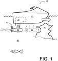
- FIG. 1 there is shown an illustrative side view of a contemporary aquatic vessel indicated generally by 10 .
- the aquatic vessel 10 is susceptible to being implemented, for example, as a yacht, ship or boat.
- the aquatic vessel 10 includes a hull 20 .
- One or more engine assemblies 30 are mounted towards a rear end of the hull 20 , wherein the one or more engine assemblies 30 are operable to provide motive power to propel the vessel 10 through water 40 .
- each of the one or more engine assemblies 30 include an extension 50 including one or more propellers 60 at substantially a distal end of the extension 50 remote from the hull 20 .
- the extension 50 protrudes into the water 40 beneath the hull 20 when the aquatic vessel 10 is in operation.
- the one or more extensions 50 are potentially vulnerable regions of the vessel 10 in an event that the one or more extensions 50 impact onto submerged objects 70 , for example submerged rocks, submerged harbour structures, ship wrecks and sunken components such as discarded oil rig components.
- Contemporary yachts weigh in a range of 10 to 75 tonnes and are often equipped with two engine assemblies each delivering 250 kW output power or four engine assemblies each delivering 750 kW output power. Moreover, these contemporary yachts are operable to attain speeds in a range of 3 to 45 knots (circa 5 km/h to 80 km/h). In operation, these contemporary yachts are susceptible of having an operative kinetic energy approaching several MegaJoules. Such a large amount of kinetic energy focussed inappropriately in the aquatic vessel 10 is an impact situation is susceptible to causing considerable damage.
- US 2 917 019 represents the closest prior art and relates to the provision of an improved insertable motor mounting structure for a boat in combination with the protection of a motor boat propeller and its operating mechanism.
- An object of the present invention is to provide a breakaway safety system which better protects an aquatic vessel in an event of potential impact.
- a breakaway safety system as claimed in appended claim 1: there is provided a breakaway safety system for a vessel, the vessel including
- the invention is of advantage that use of the one or more fracturing devices to separate the one or more propeller extensions in a controlled manner is capable of improving safety and reducing the at least one hull from becoming damaged.
- the one or more fracturing devices each includes an energy storage element, a piercing element operable to fracture its associated fracturable region when impacting thereinto, and wherein the energy storage element when activated is operable to apply a force to the piercing element to force it into the fracturable region to cause the fracturable region to fracture.
- Use of the energy storage element is beneficial in jettisoning the one or more propeller extensions more rapidly from the at least one hull in comparison to relying on unassisted fracturing of the one or more propeller extensions from the hull in direct response to excessive applied stress as employed in contemporary known solutions.
- the energy storage element includes at least one of: an explosive charge, a mechanical spring, a volume of compressed gas. Use of such energy storage elements is capable of providing considerable immediate energy for jettisoning the one or more propeller extensions from the at least one hull.
- control unit is provided with the input signals from one or more of:
- control unit includes a data recorder for recording a sequence of the one or more input signals in a period prior to jettisoning the one or more propeller extensions from the hull.
- a data recorder for recording a sequence of the one or more input signals in a period prior to jettisoning the one or more propeller extensions from the hull.
- Use of such a data recorder is useful for determining whether or not the system has responded in an intended manner for avoiding damage to the at least one hull. Such information is relevant for insurance purposes for example.
- the fracturing device is operable to be disarmed when the vessel is in a stationary state in water, thereby preventing activation of the fracturing device when in the disarmed state.
- Such disarming of the piercing device is valuable for substantially preventing any risk of jettisoning one or more propeller extensions when the vessel is substantially stationary.
- a method as claimed in appended claim 7 there is provided a method of providing a vessel with breakaway safety using a breakaway safety system, the vessel including
- the method includes steps of:
- the energy storage element includes at least one of: an explosive charge, a mechanical spring, a volume of compressed gas.
- control unit is provided with the input signals from one or more of:
- the method includes a step of:
- the method includes a step of disarming the fracturing device when the vessel is in a stationary state in water, thereby preventing activation of the fracturing device when in the disarmed state.
- a software product stored on data carrier, the software product being executable in computing hardware for implementing a method pursuant to the second aspect of the invention.
- a method of protecting a hull of a vessel in an event of a potential impact including one or more engine arrangements, and one of more propeller extensions coupled to the one or more engine arrangements for receiving motive power therefrom in operation, the method including steps of:
- an aquatic vessel equipped with a breakaway safety system pursuant to the first aspect of the invention.
- the present invention is concerned with breakaway safety systems for use in aquatic vessels.
- the vessels each include one or more hulls wherein one or more of the hulls are equipped with one or more engine assemblies whose one or more propeller assemblies protrude in a region of water beneath the one or more hulls when the vessels are in operation.
- One or more propeller assemblies are coupled to their respective one or more hulls by corresponding one or more sacrificial breakable regions which is susceptible to being triggered from an intact state to a fractured state by control signals generated in expectation of an impact event, thereby preventing the one or more hulls being stressed as occurs with contemporary known safety breakaway systems.
- the present invention is of benefit in that the one or more propeller assemblies are capable of not being jettisoned unnecessarily, thereby saving repair costs.
- the present invention is distinguished in that pre-stored energy is released in a controlled manner and at an appropriate time and situation to fracture a mechanical connection between a propeller assembly and its associated engine assembly for jettisoning the propeller assembly.
- the pre-stored energy can be derived for an explosive pyrotechnics component, from a compressed gas chamber or any other type of energy storage element operable to generate a mechanical force of sufficient magnitude to fracture the mechanical connection.
- the propeller assembly is susceptible to being jettisoned from its engine assembly and associated hull potentially within milliseconds within the engine assembly and its hull being stressed, thereby averting any damage from occurring thereto.
- the pre-stored energy is susceptible to being released in response to a control signal output Q from a control unit changing from an inactive state to an active state.
- the control unit is coupled to one or more sensors which are operable to measure various parameters in their associated aquatic vessel, In an event that certain conditions arise is respect of the various parameters as detected by the control unit, the control unit is operable to switch its aforesaid control signal output from the inactive state to the active state.
- the control unit is beneficially implemented in analogue electronic circuits, digital electronic circuits and/or computing hardware operable to execute a software product recorded on a data carrier.
- the data carrier is optionally non-volatile solid state memory or a magnetic or optical data recording medium.
- the vessel 10 includes an engine transmission housing 110 into which is accommodated a transmission shaft 120 which is operable to rotate relative to the transmission housing 110 to deliver mechanical propulsion power in use.
- the transmission housing 110 is attached by way of fasteners 140 , for example threaded bolts, to a mounting plate 130 of the aforementioned extension 50 .
- the extension 50 beneficially includes a wing member as illustrated formed in a manner of a vane.
- a transmission unit 150 is included at distal end of the extension 50 for coupling power delivered via the transmission shaft 120 to clockwise and anticlockwise rotations for driving a pair of mutually counter-rotating propellers 160 , 165 implemented to pull the vessel 10 through the water 40 in a tractor manner in a direction denoted by an arrow 170 .
- the transmission housing 110 namely a part of a suspension structure of the vessel 10 , includes a rounded annular recess 180 defining a relative thin annular fracture region 190 .
- a fracture initiating device 200 In close vicinity to the annular recess 180 are positioned one of more fracture initiating devices indicated generally by 200 .
- Each fracture initiating device 200 includes a pointed piercing element 210 , an energy storage element 220 spatially behind the piercing element 210, and a detonator 230 adjacent to the energy storage element 220 .
- the energy storage element 220 is an explosive pyrotechnics device operable when detonated to force, as denoted by an arrow 240 , the piercing element 210 into an end surface of the rounded annular recess 180 to cause the annular fracture region 190 to fracture.
- the transmission shaft 120 is disconnectably enmeshed into the transmission unit 150 so that the extension 50 is capable of being jettisoned in an event of potential impact with the submerged object 70 .
- the fracture initiating device 200 is coupled to a control unit 250 which, in turn, is connected to receive signals from one or more sensors denoted by 260 .
- the control unit 250 is operable to continuously monitor signals provided by the one or more sensors 260 and detonate or otherwise activate the one or more fracture initiating devices 200 in an event that the signals indicate that an impact is imminent or in a process of occurring. Operation of the control unit 250 will be elucidated in greater detail later.
- the fracture initiating device 200 is susceptible to being implemented in several different ways. When it is implemented as a pyrotechnics device, a very considerable amount of energy is susceptible to being substantially immediately release from the energy storage element 220 to propel the pointed piercing element 210 to fracture the annular fracture region 190 .
- pyrotechnics devices in a manner akin to air-bags in vehicles, are potentially susceptible to exploding spontaneously if their explosive charge deteriorates; however, when contemporary pyrotechnics materials are employed, a risk of such spontaneous detonation is relatively low.
- the control unit 250 is operable to monitor whether or not one or more engine assemblies 30 of the vessel 10 are actively in operation, namely supplied with fuel with their internal parts rotating.
- the fracture initiating device 200 is beneficially is switched to its disarmed state, for example by way of a disarming signal A issued from the control unit 250.
- the fracture initiating device 200 is armed so as to be able to release its energy in an event that the control signal Q from the control unit 250 indicates that the propeller assembly 50 is to be jettisoned.
- FIG. 3 A first alternative implementation of the fracture initiating device 200 is illustrated in Figure 3 ; the alternative fracture initiating device is indicated generally by 300.
- the fracture initiating device 300 is shown in its non-deployed state.
- the fracture initiating device 300 includes a robust mechanical housing 310 including a compressed helical spring 320 as an energy storage device.
- the compressed spring 320 includes a first end thereof abutting onto an end face of the robust housing 310, and a second end thereof abutting onto a rear face of hammer component 330.
- This hammer component 330 includes a waist region into which a retaining pin 335 is engaged to prevent the hammer component 330 being ejected from the robust housing 310.
- the hammer component 330 includes an impact plate for impacting in operation onto a rear end of the pointed piercing element 210 when the fracture initiating device 300 is deployed.
- the retaining pin 335 is coupled to an actuator 340, for example an electro-magnetic solenoid actuator, which is energized by way of the signal Q when the device 300 is to be deployed.
- an actuator 340 for example an electro-magnetic solenoid actuator, which is energized by way of the signal Q when the device 300 is to be deployed.
- the control unit 250 energized the actuator 340 to cause the retaining pin 335 to be retracted laterally as denoted by an arrow 350 to enable the spring 320 to accelerate the hammer component 330 to impact onto the piercing element 200 to cause.
- the piercing element 200 to fracture the annular fracture region 190 .
- the fracture initiating devices 200 , 300 employ linearly-acting energy storage arrangements for forcing the piercing element 210 to fracture the fracture region 190 .
- the fracture initiating device 400 includes a hammer component 410 which is rotatably mounted at a pivot 420 . Moreover, the hammer component 410 is furnished with a spiral spring 430 which functions in operation as a mechanical energy storage component.
- the hammer component 410 includes a hammer surface adapted to impact upon the rear end of the pointed piercing component 210 when the fracture initiating device 400 is deployed in operation.
- the device 400 includes a retaining portion provided with an indented notch comprising an abrupt edge.
- the hammer component 410 includes an L-shaped release member 460 also arranged to rotate substantially at a central portion thereof about a pivot 470 in operation.
- a retaining edge 480 at a first remote end of the release member 460 is engaged into the aforementioned indented notch to prevent the hammer component 410 rotating in response to rotational force applied thereby by the spiral spring 430 .
- the release member 460 When a force is applied to a second remote end of the release member 460 as illustrated, for example the force being provided from an electromagnetic actuator controlled via the output Q from the control unit 250 , the release member 460 is forced to rotate about its pivot 470 and thereby causes the retaining edge 480 to disengage with the indented notch. As a result, the spiral spring 430 rotationally accelerates the hammer component 410 to impact onto the pointed piercing element 210 . The piercing element 210 is, in turn, forced into the annular fracture region 190 causing the region 190 to fracture, thereby enabling the extension 50 to be safely jettisoned.
- the device 500 includes a robust housing 510 having a cavity 520 therein filled with a gas at high pressure, for example in a range of 50 to 100 Bar.
- the robust housing 510 includes a valve 530 , for example a needle valve, included within a venting tube linking the cavity 520 to a piston chamber 550 ; the valve 530 is coupled to an actuator 540 which is operable to receive the signal Q and to control release of the valve 530 .
- the valve 530 is in a closed state to prevent loss of gas from the chamber 520 .
- the piercing element 210 is provided with a piston member 560 provided with an annual flexible seal 570 for ensuring a gas-tight seal to inside walls of the of the piston chamber 550 .
- control unit 250 In operation, when the control unit 250 detects that an impact event is imminent or commenced, the control unit 250 switches a state of its output Q from an inactive state to an active state to cause the actuator 540 to release the valve 530 to allow pressurized gas within the cavity 520 into the piston chamber 550 to propel the piercing element 210 into the fracture region 190 to jettison the extension 50 from the hull 20 .
- a separation is beneficially provided between a pointed tip of the piercing element 210 and an impact surface of the fracture region 190 so that the piercing element 210 is accelerated before it impacts, thereby providing greater fracturing force to the piercing element 210 .
- control unit 250 is coupled to a data-bus of the vessel 10 , for example to a CAN data-bus; when such a CAN data-bus is provided in the vessel 10 , the control unit 250 is able to receive signal data which is conveyed via this data-bus.
- the control unit 250 includes a data recorder, for example in a manner of a "black box" data recorder, for enabling signal characteristics leading up to jettisoning of the extension 50 to be retrospectively analysed, for example for insurance purposes.
- the one or more sensors 260 beneficially include one or more of:
- the algorithm F is optionally operable to activate its output Q on a combination of parameters (a) to (f) being simultaneously satisfied.
- the vessel 10 is potentially more likely to suffer damage at a relatively lower speed in a harbour when its extension 50 impacts onto a submerged structure in the harbour than at high speed when the running onto a sandbank when considerable flow of water accompanies motion of the vessel 10 .
- the breakaway safety system is also operable to protect one or more persons on board the vessel 10 which may be susceptible to being thrown overboard in a situation that the vessel 10 is suddenly decelerated as a result of one or more of its extensions 50 impacting onto one or more submerged objects.
- the control unit 250 includes a processor 600 coupled to a data memory 610 including one or more executable software products.
- the one or more software products are downloadable to the data memory 610 via a physical data carrier such as a plug-in read only memory (ROM) and/or via a signal coupled to the control unit 250 , wherein the signal is operable to function as a data carrier.
- ROM read only memory
- the signal is operable to function as a data carrier.
- one or more software products in the data-memory 610 are thereby susceptible to being updated.
- the aforesaid one or more software products executed within the processor 600 are operable to implement an algorithm corresponding to a method of processing signals provided from n sensors denoted by S 1 to S n constituting the one or more sensors 260 ; n is an integer of value unity or greater. Moreover, the aforementioned outputs Q, A are generated by the control unit as an output of executing the one or more software products upon the processor 600.
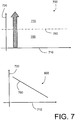
- a schematic illustrative graph is shown in Figure 7 to elucidate operation of the one or more software products.
- An abscissa axis 710 represents a speed of the vessel 10, either forwards or reverse.
- an ordinate axis 720 represents whether or not the fracture initiating device 200, or alternative implementation thereof, is to be activated or not, namely a representation of the signal Q .
- the threshold Th is a function of a speed of the vessel 10 as indicated by 800 such that the extension 50 is more readily jettisoned when the vessel 10 is travelling at high speeds to prevent damage occurring to the hull 20 .
- the algorithm implemented in the processor 600 is operable to set the output signal A to a disarmed state, when relevant to the implementation of the piercing device 200 and its alternative implementations, when the vessel 10 is stationary, namely not having any of forward or reverse gears engaged in the vessel 10 .
- the algorithm F is optionally operable to activate the output Q in an event that any one of several criteria are satisfied as follows:
- the piercing device 200 is only activated provided that the engine arrangement 30 of the vessel 10 is running, the vessel 10 is engaged in gear for coupling propulsion to its one or more propellers, and the engine arrangement has an RPM rate exceeding a threshold, for example 1200 RPM.
- RPM is an abbreviation for revolutions per minute.
- the propeller extension 50 is provided with one or more features which enabled it to be located when jettisoned from the vessel 10 in operation.
- the one or more features include:
Landscapes
- Chemical & Material Sciences (AREA)
- Engineering & Computer Science (AREA)
- Combustion & Propulsion (AREA)
- Mechanical Engineering (AREA)
- Ocean & Marine Engineering (AREA)
- Health & Medical Sciences (AREA)
- Public Health (AREA)
- Geophysics And Detection Of Objects (AREA)
Claims (14)
- système de largage sécurisé pour un navire (10), ledit navire (10) comportant(a) au moins une coque (20) ;(b) un ou plusieurs agencement(s) de moteur (30) supporté(s) par ladite au moins une coque (20) ; et(c) une ou plusieurs extension(s) d'hélice (50) montée(s) sur ladite au moins une coque (20) et couplée(s) pour recevoir une force motrice à partir dudit ou desdits plusieurs agencement(s) de moteur (30) lors du fonctionnement ;caractérisé en ce que
ledit système de sécurité comporte :un ou plusieurs capteur(s) monté(s) sur ledit navire (10) pour mesurer des paramètres de fonctionnement dudit navire (10) et pour générer un signal ou plusieurs signaux d'entrée correspondant(s) ;une unité de commande (250) pour recevoir ledit signal ou lesdits plusieurs signaux d'entrée correspondant(s), et pour traiter ledit signal ou lesdits plusieurs signaux d'entrée afin de générer au moins une sortie de commande (Q, A) ;une ou plusieurs région(s) pouvant être fracturée(s) (190) pour monter ladite ou lesdites plusieurs extension(s) d'hélice (50) sur ladite au moins une coque (20) ; etun ou plusieurs dispositif(s) de fracturation (200, 300, 400, 500) pouvant fonctionner pour fracturer ladite ou lesdites plusieurs région(s) pouvant être fracturée(s) (190) afin de larguer une ou plusieurs extension(s) d'hélice associée(s) (50) dans un évènement dans lequel ladite unité de commande (250) détecte un évènement d'impact potentiellement dangereux et active l'au moins une sortie de commande (Q, A) en conséquence. - Système de largage sécurisé tel que revendiqué dans la revendication 1, dans lequel ledit ou lesdits plusieurs dispositif(s) de fracturation (200, 300, 400, 500) comportent chacun un élément de stockage d'énergie (230, 320, 430, 520), un élément de perforation (210) pouvant fonctionner pour fracturer sa région pouvant être fracturée associée (190) lorsqu'il agit sur celui-ci, et dans lequel ledit élément de stockage d'énergie (230, 320, 430, 520) lorsqu'il est activé peut fonctionner pour appliquer une force audit élément de perforation (210) pour le forcer dans ladite région pouvant être fracturée (190) afin d'amener ladite région pouvant être fracturée (190) à être fracturée.
- Système de largage sécurisé tel que revendiqué dans la revendication 2, dans lequel ledit élément de stockage d'énergie (230, 320, 430, 520) comporte au moins l'un(e) : d'une charge explosive, d'un ressort mécanique, d'un volume de gaz comprimé.
- Système de largage sécurisé tel que revendiqué dans la revendication 1 ou 2, dans lequel ladite unité de commande (250) est munie des signaux d'entrée provenant d'un ou de plusieurs parmi :(a) un capteur de déformation monté sur ladite au moins une coque (20) dudit navire (10) ;(b) un capteur de déformation monté sur ladite ou lesdites plusieurs région(s) pouvant être fracturée(s) (190) ;(c) un capteur de vitesse de rotation de moteur pouvant fonctionner pour mesurer une vitesse de rotation d'un ou de plusieurs agencement(s) de moteur (30) dudit navire ;(d) un capteur de vitesse pouvant fonctionner pour mesurer une vitesse du navire (10) dans l'eau (40) ;(e) un accéléromètre monté sur ledit navire (10), ou sur ladite extension (50) de celui-ci, pour mesurer l'accélération et/ou la décélération de celui-ci ;(f) un capteur de vitesse de giration pour mesurer les changements de l'orientation angulaire sur ledit navire (10) ;(g) un capteur d'engrènement d'engrenage pour mesurer l'engrènement d'un ou de plusieurs engrenage(s) d'entraînement dudit navire (10) ; et(h) un capteur sonar pour détecter la présence d'un ou de plusieurs objet(s) sous, derrière et/ou devant le navire (10) susceptible de présenter un danger d'impact pour le navire (10) lors de son fonctionnement.
- Système de largage sécurisé tel que revendiqué dans l'une quelconque des revendications précédentes, dans lequel ladite unité de commande (250) comporte un enregistreur de données pour enregistrer une séquence dudit signal ou desdits plusieurs signaux d'entrée dans une période préalable au largage de ladite ou desdites plusieurs extension(s) d'hélice à partir de ladite coque (20).
- Système de largage sécurisé tel que revendiqué dans l'une quelconque des revendications précédentes, dans lequel ledit dispositif de fracturation (200) peut fonctionner pour être désarmé lorsque ledit navire (10) est dans un état stationnaire dans l'eau (40), empêchant ainsi l'activation dudit dispositif de fracturation (200) dans ledit état désarmé.
- Procédé pour fournir à un navire (10) avec une sécurité de largage en utilisant un système de largage sécurisé, ledit navire comportant(a) au moins une coque (20) ;(b) un ou plusieurs agencement(s) de moteur (30) supporté(s) par l'au moins une coque (20) ; et(c) une ou plusieurs extension(s) d'hélice (50) montée(s) sur l'au moins une coque (20) et couplée(s) pour recevoir une force motrice à partir dudit ou desdits plusieurs agencement(s) de moteur (30) lors du fonctionnement ;caractérisé en ce que ledit procédé comporte les étapes qui consistent :(d) à monter ladite ou lesdites plusieurs extension(s) d'hélice (50) sur ladite coque (20) par une ou plusieurs région(s) pouvant être fracturée(s) (190) ;(e) à agencer un ou plusieurs capteur(s) monté(s) sur ledit navire (10) pour mesurer des paramètres de fonctionnement dudit navire (10) et pour générer un signal ou plusieurs signaux d'entrée correspondant(s) ;(f) à agencer une unité de commande (250) pour recevoir ledit signal ou lesdits plusieurs signaux d'entrée correspondant(s), et pour traiter ledit signal ou lesdits plusieurs signaux d'entrée afin de générer au moins une sortie de commande (Q, A) ; et(g) à utiliser un ou plusieurs dispositif(s) de fracturation (200, 300, 400, 500) pour fracturer ladite ou lesdites plusieurs région(s) pouvant être fracturée(s) (190) afin de larguer une ou plusieurs extension(s) d'hélice associée(s) (50) dans un évènement dans lequel ladite unité de commande (250) détecte un événement d'impact potentiellement dangereux et active l'au moins une sortie de commande (Q, A) en conséquence.
- Procédé tel que revendiqué dans la revendication 7, comportant les étapes qui consistent :(h) à agencer ledit ou lesdits plusieurs dispositif(s) de fracturation (200, 300, 400, 500) pour comporter chacun un élément de stockage d'énergie (230, 320, 430, 520), un élément de perforation (210) pouvant fonctionner pour fracturer sa région pouvant être fracturée associée (190) lorsqu'il agit sur celui-ci ; et(i) à utiliser ledit élément de stockage d'énergie (230, 320, 430, 520) lorsqu'il est activé pour appliquer une force audit élément de perforation (210) pour le forcer dans ladite région pouvant être fracturée (190) afin d'amener ladite région pouvant être fracturée (190) à être fracturée.
- Procédé tel que revendiqué dans la revendication 8, dans lequel ledit élément de stockage d'énergie (230, 320, 430, 520) comporte au moins l'un(e) : d'une charge explosive, d'un ressort mécanique, d'un volume de gaz comprimé.
- Procédé tel que revendiqué dans la revendication 7 ou 8, dans lequel ladite unité de commande (250) est munie des signaux d'entrée provenant d'un ou de plusieurs parmi :(a) un capteur de déformation monté sur ladite au moins une coque (20) dudit navire (10) ;(b) un capteur de déformation monté sur ladite ou lesdites plusieurs région(s) pouvant être fracturée(s) (190) ;(c) un capteur de vitesse de rotation de moteur pouvant fonctionner pour mesurer une vitesse de rotation d'un ou de plusieurs agencement(s) de moteur (30) dudit navire ;(d) un capteur de vitesse pouvant fonctionner pour mesurer une vitesse du navire (10) dans l'eau (40) ;(e) un accéléromètre monté sur ledit navire (10), ou sur ladite extension (50) de celui-ci, pour mesurer l'accélération et/ou la décélération de celui-ci ;(f) un capteur de vitesse de giration pour mesurer les changements de l'orientation angulaire dudit navire (10) ou d'une partie de celui-ci ;(g) un capteur d'engrènement d'engrenage pour mesurer l'engrènement d'un ou de plusieurs engrenage(s) d'entraînement dudit navire (10) ; et(h) un capteur sonar pour détecter la présence d'un ou de plusieurs objet(s) sous, derrière et/ou devant le navire (10) susceptible de présenter un danger d'impact pour le navire (10) lors de son fonctionnement.
- Procédé tel que revendiqué dans l'une quelconque des revendications 7 à 10, comportant une étape qui consiste :(i) à enregistrer, en utilisant un enregistreur de données, une séquence dudit signal ou desdits plusieurs signaux d'entrée dans une période préalable au largage de ladite ou desdites plusieurs extension(s) d'hélice à partir de ladite au moins une coque (20).
- Procédé tel que revendiqué dans l'une quelconque des revendications 7 à 11, dans lequel ledit procédé comporte une étape qui consiste à désarmer ledit dispositif de fracturation (200) lorsque ledit navire (10) est dans un état stationnaire dans l'eau (40), empêchant ainsi l'activation dudit dispositif de fracturation (200) dans ledit état désarmé.
- Produit logiciel stocké sur un support de données, ledit produit logiciel étant exécutable dans un matériel informatique (600, 610) pour mettre en oeuvre un procédé tel que revendiqué dans l'une quelconque des revendications 7 à 12.
- Navire aquatique (10) équipé d'un système de largage sécurisé tel que revendiqué dans l'une quelconque des revendications 1 à 6.
Applications Claiming Priority (1)
| Application Number | Priority Date | Filing Date | Title |
|---|---|---|---|
| PCT/SE2008/000088 WO2009096823A1 (fr) | 2008-01-31 | 2008-01-31 | Système de larguage sécurisé |
Publications (3)
| Publication Number | Publication Date |
|---|---|
| EP2247495A1 EP2247495A1 (fr) | 2010-11-10 |
| EP2247495A4 EP2247495A4 (fr) | 2015-05-27 |
| EP2247495B1 true EP2247495B1 (fr) | 2017-03-08 |
Family
ID=40913015
Family Applications (1)
| Application Number | Title | Priority Date | Filing Date |
|---|---|---|---|
| EP08712701.5A Not-in-force EP2247495B1 (fr) | 2008-01-31 | 2008-01-31 | Système de larguage sécurisé |
Country Status (3)
| Country | Link |
|---|---|
| US (1) | US8267731B2 (fr) |
| EP (1) | EP2247495B1 (fr) |
| WO (1) | WO2009096823A1 (fr) |
Families Citing this family (13)
| Publication number | Priority date | Publication date | Assignee | Title |
|---|---|---|---|---|
| WO2009142553A1 (fr) | 2008-05-22 | 2009-11-26 | Ab Volvo Penta | Carter pour navire aquatique, système de sécurité à décrochage pour navire aquatique et navire aquatique |
| US8994562B1 (en) * | 2011-12-06 | 2015-03-31 | Shane Daniel | Boat monitoring systems and methods |
| US9701381B2 (en) * | 2013-12-10 | 2017-07-11 | Caterpillar Inc. | Breakaway skeg for a marine propulsion unit |
| CN104163236B (zh) * | 2014-05-13 | 2016-06-29 | 浙江海洋学院 | 防触礁运输船 |
| US11353566B2 (en) | 2018-04-26 | 2022-06-07 | Navico Holding As | Sonar transducer having a gyroscope |
| US11221403B2 (en) * | 2018-05-21 | 2022-01-11 | Navico Holding As | Impact detection devices and methods |
| US10793245B1 (en) * | 2019-06-13 | 2020-10-06 | Daniel Scott Trotter | Boat safety system |
| CA3170057A1 (fr) | 2020-02-06 | 2021-09-10 | Austin Star Detonator Company | Capteurs integres pour detonateur |
| USD1026955S1 (en) | 2020-06-23 | 2024-05-14 | Brunswick Corporation | Stern drive |
| US11208190B1 (en) | 2020-06-23 | 2021-12-28 | Brunswick Corporation | Stern drives having breakaway lower gearcase |
| CN112572729A (zh) * | 2020-12-31 | 2021-03-30 | 天津中海油能源发展油田设施管理有限公司 | 节能型四机双桨推进系统 |
| CN115476963B (zh) * | 2022-09-28 | 2025-07-18 | 重庆大学 | 一种船载水下破障装备及破障方法 |
| CN117104433B (zh) * | 2023-09-20 | 2024-07-23 | 海底鹰深海科技股份有限公司 | 抛弃式声纳以及抛弃式声纳和船舶的交互方法 |
Family Cites Families (7)
| Publication number | Priority date | Publication date | Assignee | Title |
|---|---|---|---|---|
| US2124497A (en) * | 1934-06-18 | 1938-07-19 | Harold W Slauson | Safety device for marine power plants |
| US2917019A (en) | 1955-02-16 | 1959-12-15 | Fred C Krueger | Propeller housing attachments |
| US3470844A (en) * | 1968-01-04 | 1969-10-07 | Dana Corp | Marine outdrive latch |
| DE2627953C3 (de) | 1976-06-22 | 1980-05-14 | Schottel-Werft Josef Becker Gmbh & Co Kg, 5401 Spay | Schutzvorrichtung für Ruderpropeller, Z-Triebe o.a. Antriebe von Wasserfahrzeugen |
| JPH0631072B2 (ja) * | 1985-06-05 | 1994-04-27 | 三信工業株式会社 | 船舶推進機の航走安定装置 |
| US5238432A (en) * | 1991-10-17 | 1993-08-24 | Renner Howard E | Marine drive unit impact avoidance system |
| AU2003280283A1 (en) * | 2002-12-03 | 2004-06-23 | Supraventures Ag | Watercraft |
-
2008
- 2008-01-31 US US12/812,478 patent/US8267731B2/en active Active
- 2008-01-31 EP EP08712701.5A patent/EP2247495B1/fr not_active Not-in-force
- 2008-01-31 WO PCT/SE2008/000088 patent/WO2009096823A1/fr not_active Ceased
Non-Patent Citations (1)
| Title |
|---|
| None * |
Also Published As
| Publication number | Publication date |
|---|---|
| US8267731B2 (en) | 2012-09-18 |
| WO2009096823A1 (fr) | 2009-08-06 |
| EP2247495A1 (fr) | 2010-11-10 |
| EP2247495A4 (fr) | 2015-05-27 |
| US20100291816A1 (en) | 2010-11-18 |
Similar Documents
| Publication | Publication Date | Title |
|---|---|---|
| EP2247495B1 (fr) | Système de larguage sécurisé | |
| US4231311A (en) | Towable pod assembly for protectively disabling incoming torpedoes | |
| EP3508426A1 (fr) | Petit corps volant pourvu d'un dispositif de coussin de sécurité gonflable | |
| JPS6228399B2 (fr) | ||
| JP2008260413A (ja) | 船舶用エンジン緊急停止装置及び船舶用事故判定装置 | |
| WO2019181989A1 (fr) | Dispositif d'actionnement d'objet volant, procédé de prévention de dysfonctionnement pour dispositif de commande d'objet volant, dispositif de génération de poussée d'objet volant, dispositif de déploiement de parachute ou de parapente, et dispositif de coussin de sécurité gonflable | |
| KR20200013539A (ko) | 비상 탈출용 구명정 | |
| US8028637B2 (en) | Method of intercepting and yawing a sailing vessel with external propulsion means | |
| US8552282B1 (en) | Propulsion defeating system | |
| EP0847360B1 (fr) | Engin submersible destine a neutraliser des mines | |
| US8371204B2 (en) | Bubble weapon system and methods for inhibiting movement and disrupting operations of vessels | |
| US6695654B2 (en) | Retractable rudder system for water jet pump vessels | |
| JPH06211190A (ja) | 船舶の運航制御装置 | |
| EP1834154B1 (fr) | Appareil permettant de modifier le parcours d'un article mobile et procede associe | |
| CN106347689A (zh) | 一种黑匣子分离控制方法、系统和航空器 | |
| KR101971853B1 (ko) | 역추진형 선박 감속 장치 | |
| US20250074562A1 (en) | Marine vessel disablement system and method | |
| US6082266A (en) | Air-cushion and accurate mine laying and mapping system | |
| US7576281B2 (en) | Apparatus for altering the course of travelling of a moving article and a method thereof | |
| CN115136092A (zh) | 无人驾驶飞行器、计算机程序和用于减少由于无人驾驶飞行器的碰撞而对环境造成的损害的方法 | |
| KR102894958B1 (ko) | 분리식 잠수정용 비상탈출시스템 | |
| KR102892208B1 (ko) | 장치 일부의 회수가 가능한 자폭형 수중드론 | |
| KR101386436B1 (ko) | 침몰지연장치가 설치된 선박 | |
| US20260109440A1 (en) | Payload re-positioning system for a maritime vehicle | |
| EP0514567B1 (fr) | Mécanisme d'éjection de l'equipage d'un avion |
Legal Events
| Date | Code | Title | Description |
|---|---|---|---|
| PUAI | Public reference made under article 153(3) epc to a published international application that has entered the european phase |
Free format text: ORIGINAL CODE: 0009012 |
|
| 17P | Request for examination filed |
Effective date: 20100831 |
|
| AK | Designated contracting states |
Kind code of ref document: A1 Designated state(s): AT BE BG CH CY CZ DE DK EE ES FI FR GB GR HR HU IE IS IT LI LT LU LV MC MT NL NO PL PT RO SE SI SK TR |
|
| AX | Request for extension of the european patent |
Extension state: AL BA MK RS |
|
| DAX | Request for extension of the european patent (deleted) | ||
| RA4 | Supplementary search report drawn up and despatched (corrected) |
Effective date: 20150428 |
|
| RIC1 | Information provided on ipc code assigned before grant |
Ipc: B63B 43/18 20060101AFI20150421BHEP Ipc: B63H 5/07 20060101ALI20150421BHEP |
|
| GRAP | Despatch of communication of intention to grant a patent |
Free format text: ORIGINAL CODE: EPIDOSNIGR1 |
|
| INTG | Intention to grant announced |
Effective date: 20160831 |
|
| GRAS | Grant fee paid |
Free format text: ORIGINAL CODE: EPIDOSNIGR3 |
|
| GRAJ | Information related to disapproval of communication of intention to grant by the applicant or resumption of examination proceedings by the epo deleted |
Free format text: ORIGINAL CODE: EPIDOSDIGR1 |
|
| GRAL | Information related to payment of fee for publishing/printing deleted |
Free format text: ORIGINAL CODE: EPIDOSDIGR3 |
|
| INTC | Intention to grant announced (deleted) | ||
| GRAR | Information related to intention to grant a patent recorded |
Free format text: ORIGINAL CODE: EPIDOSNIGR71 |
|
| GRAA | (expected) grant |
Free format text: ORIGINAL CODE: 0009210 |
|
| AK | Designated contracting states |
Kind code of ref document: B1 Designated state(s): AT BE BG CH CY CZ DE DK EE ES FI FR GB GR HR HU IE IS IT LI LT LU LV MC MT NL NO PL PT RO SE SI SK TR |
|
| INTG | Intention to grant announced |
Effective date: 20170130 |
|
| REG | Reference to a national code |
Ref country code: GB Ref legal event code: FG4D |
|
| REG | Reference to a national code |
Ref country code: CH Ref legal event code: EP Ref country code: AT Ref legal event code: REF Ref document number: 873257 Country of ref document: AT Kind code of ref document: T Effective date: 20170315 |
|
| REG | Reference to a national code |
Ref country code: IE Ref legal event code: FG4D |
|
| REG | Reference to a national code |
Ref country code: DE Ref legal event code: R096 Ref document number: 602008049072 Country of ref document: DE |
|
| REG | Reference to a national code |
Ref country code: LT Ref legal event code: MG4D |
|
| REG | Reference to a national code |
Ref country code: NL Ref legal event code: MP Effective date: 20170308 |
|
| PG25 | Lapsed in a contracting state [announced via postgrant information from national office to epo] |
Ref country code: HR Free format text: LAPSE BECAUSE OF FAILURE TO SUBMIT A TRANSLATION OF THE DESCRIPTION OR TO PAY THE FEE WITHIN THE PRESCRIBED TIME-LIMIT Effective date: 20170308 Ref country code: GR Free format text: LAPSE BECAUSE OF FAILURE TO SUBMIT A TRANSLATION OF THE DESCRIPTION OR TO PAY THE FEE WITHIN THE PRESCRIBED TIME-LIMIT Effective date: 20170609 Ref country code: FI Free format text: LAPSE BECAUSE OF FAILURE TO SUBMIT A TRANSLATION OF THE DESCRIPTION OR TO PAY THE FEE WITHIN THE PRESCRIBED TIME-LIMIT Effective date: 20170308 Ref country code: NO Free format text: LAPSE BECAUSE OF FAILURE TO SUBMIT A TRANSLATION OF THE DESCRIPTION OR TO PAY THE FEE WITHIN THE PRESCRIBED TIME-LIMIT Effective date: 20170608 Ref country code: LT Free format text: LAPSE BECAUSE OF FAILURE TO SUBMIT A TRANSLATION OF THE DESCRIPTION OR TO PAY THE FEE WITHIN THE PRESCRIBED TIME-LIMIT Effective date: 20170308 |
|
| REG | Reference to a national code |
Ref country code: AT Ref legal event code: MK05 Ref document number: 873257 Country of ref document: AT Kind code of ref document: T Effective date: 20170308 |
|
| PG25 | Lapsed in a contracting state [announced via postgrant information from national office to epo] |
Ref country code: LV Free format text: LAPSE BECAUSE OF FAILURE TO SUBMIT A TRANSLATION OF THE DESCRIPTION OR TO PAY THE FEE WITHIN THE PRESCRIBED TIME-LIMIT Effective date: 20170308 Ref country code: SE Free format text: LAPSE BECAUSE OF FAILURE TO SUBMIT A TRANSLATION OF THE DESCRIPTION OR TO PAY THE FEE WITHIN THE PRESCRIBED TIME-LIMIT Effective date: 20170308 Ref country code: BG Free format text: LAPSE BECAUSE OF FAILURE TO SUBMIT A TRANSLATION OF THE DESCRIPTION OR TO PAY THE FEE WITHIN THE PRESCRIBED TIME-LIMIT Effective date: 20170608 Ref country code: ES Free format text: LAPSE BECAUSE OF FAILURE TO SUBMIT A TRANSLATION OF THE DESCRIPTION OR TO PAY THE FEE WITHIN THE PRESCRIBED TIME-LIMIT Effective date: 20170308 |
|
| PG25 | Lapsed in a contracting state [announced via postgrant information from national office to epo] |
Ref country code: NL Free format text: LAPSE BECAUSE OF FAILURE TO SUBMIT A TRANSLATION OF THE DESCRIPTION OR TO PAY THE FEE WITHIN THE PRESCRIBED TIME-LIMIT Effective date: 20170308 |
|
| PG25 | Lapsed in a contracting state [announced via postgrant information from national office to epo] |
Ref country code: AT Free format text: LAPSE BECAUSE OF FAILURE TO SUBMIT A TRANSLATION OF THE DESCRIPTION OR TO PAY THE FEE WITHIN THE PRESCRIBED TIME-LIMIT Effective date: 20170308 Ref country code: EE Free format text: LAPSE BECAUSE OF FAILURE TO SUBMIT A TRANSLATION OF THE DESCRIPTION OR TO PAY THE FEE WITHIN THE PRESCRIBED TIME-LIMIT Effective date: 20170308 Ref country code: CZ Free format text: LAPSE BECAUSE OF FAILURE TO SUBMIT A TRANSLATION OF THE DESCRIPTION OR TO PAY THE FEE WITHIN THE PRESCRIBED TIME-LIMIT Effective date: 20170308 Ref country code: RO Free format text: LAPSE BECAUSE OF FAILURE TO SUBMIT A TRANSLATION OF THE DESCRIPTION OR TO PAY THE FEE WITHIN THE PRESCRIBED TIME-LIMIT Effective date: 20170308 Ref country code: SK Free format text: LAPSE BECAUSE OF FAILURE TO SUBMIT A TRANSLATION OF THE DESCRIPTION OR TO PAY THE FEE WITHIN THE PRESCRIBED TIME-LIMIT Effective date: 20170308 |
|
| PG25 | Lapsed in a contracting state [announced via postgrant information from national office to epo] |
Ref country code: IS Free format text: LAPSE BECAUSE OF FAILURE TO SUBMIT A TRANSLATION OF THE DESCRIPTION OR TO PAY THE FEE WITHIN THE PRESCRIBED TIME-LIMIT Effective date: 20170708 Ref country code: PL Free format text: LAPSE BECAUSE OF FAILURE TO SUBMIT A TRANSLATION OF THE DESCRIPTION OR TO PAY THE FEE WITHIN THE PRESCRIBED TIME-LIMIT Effective date: 20170308 Ref country code: PT Free format text: LAPSE BECAUSE OF FAILURE TO SUBMIT A TRANSLATION OF THE DESCRIPTION OR TO PAY THE FEE WITHIN THE PRESCRIBED TIME-LIMIT Effective date: 20170710 |
|
| REG | Reference to a national code |
Ref country code: DE Ref legal event code: R097 Ref document number: 602008049072 Country of ref document: DE |
|
| PLBE | No opposition filed within time limit |
Free format text: ORIGINAL CODE: 0009261 |
|
| REG | Reference to a national code |
Ref country code: FR Ref legal event code: PLFP Year of fee payment: 11 |
|
| STAA | Information on the status of an ep patent application or granted ep patent |
Free format text: STATUS: NO OPPOSITION FILED WITHIN TIME LIMIT |
|
| PG25 | Lapsed in a contracting state [announced via postgrant information from national office to epo] |
Ref country code: DK Free format text: LAPSE BECAUSE OF FAILURE TO SUBMIT A TRANSLATION OF THE DESCRIPTION OR TO PAY THE FEE WITHIN THE PRESCRIBED TIME-LIMIT Effective date: 20170308 |
|
| 26N | No opposition filed |
Effective date: 20171211 |
|
| PG25 | Lapsed in a contracting state [announced via postgrant information from national office to epo] |
Ref country code: SI Free format text: LAPSE BECAUSE OF FAILURE TO SUBMIT A TRANSLATION OF THE DESCRIPTION OR TO PAY THE FEE WITHIN THE PRESCRIBED TIME-LIMIT Effective date: 20170308 |
|
| REG | Reference to a national code |
Ref country code: CH Ref legal event code: PL |
|
| PG25 | Lapsed in a contracting state [announced via postgrant information from national office to epo] |
Ref country code: LU Free format text: LAPSE BECAUSE OF NON-PAYMENT OF DUE FEES Effective date: 20180131 |
|
| REG | Reference to a national code |
Ref country code: IE Ref legal event code: MM4A |
|
| REG | Reference to a national code |
Ref country code: BE Ref legal event code: MM Effective date: 20180131 |
|
| PG25 | Lapsed in a contracting state [announced via postgrant information from national office to epo] |
Ref country code: LI Free format text: LAPSE BECAUSE OF NON-PAYMENT OF DUE FEES Effective date: 20180131 Ref country code: BE Free format text: LAPSE BECAUSE OF NON-PAYMENT OF DUE FEES Effective date: 20180131 Ref country code: CH Free format text: LAPSE BECAUSE OF NON-PAYMENT OF DUE FEES Effective date: 20180131 |
|
| PG25 | Lapsed in a contracting state [announced via postgrant information from national office to epo] |
Ref country code: IE Free format text: LAPSE BECAUSE OF NON-PAYMENT OF DUE FEES Effective date: 20180131 |
|
| PG25 | Lapsed in a contracting state [announced via postgrant information from national office to epo] |
Ref country code: MC Free format text: LAPSE BECAUSE OF FAILURE TO SUBMIT A TRANSLATION OF THE DESCRIPTION OR TO PAY THE FEE WITHIN THE PRESCRIBED TIME-LIMIT Effective date: 20170308 |
|
| PG25 | Lapsed in a contracting state [announced via postgrant information from national office to epo] |
Ref country code: MT Free format text: LAPSE BECAUSE OF NON-PAYMENT OF DUE FEES Effective date: 20180131 |
|
| PG25 | Lapsed in a contracting state [announced via postgrant information from national office to epo] |
Ref country code: TR Free format text: LAPSE BECAUSE OF FAILURE TO SUBMIT A TRANSLATION OF THE DESCRIPTION OR TO PAY THE FEE WITHIN THE PRESCRIBED TIME-LIMIT Effective date: 20170308 |
|
| PG25 | Lapsed in a contracting state [announced via postgrant information from national office to epo] |
Ref country code: HU Free format text: LAPSE BECAUSE OF FAILURE TO SUBMIT A TRANSLATION OF THE DESCRIPTION OR TO PAY THE FEE WITHIN THE PRESCRIBED TIME-LIMIT; INVALID AB INITIO Effective date: 20080131 |
|
| PG25 | Lapsed in a contracting state [announced via postgrant information from national office to epo] |
Ref country code: CY Free format text: LAPSE BECAUSE OF FAILURE TO SUBMIT A TRANSLATION OF THE DESCRIPTION OR TO PAY THE FEE WITHIN THE PRESCRIBED TIME-LIMIT Effective date: 20170308 |
|
| PGFP | Annual fee paid to national office [announced via postgrant information from national office to epo] |
Ref country code: DE Payment date: 20240129 Year of fee payment: 17 Ref country code: GB Payment date: 20240123 Year of fee payment: 17 |
|
| PGFP | Annual fee paid to national office [announced via postgrant information from national office to epo] |
Ref country code: IT Payment date: 20240123 Year of fee payment: 17 Ref country code: FR Payment date: 20240125 Year of fee payment: 17 |
|
| REG | Reference to a national code |
Ref country code: DE Ref legal event code: R119 Ref document number: 602008049072 Country of ref document: DE |
|
| GBPC | Gb: european patent ceased through non-payment of renewal fee |
Effective date: 20250131 |
|
| PG25 | Lapsed in a contracting state [announced via postgrant information from national office to epo] |
Ref country code: DE Free format text: LAPSE BECAUSE OF NON-PAYMENT OF DUE FEES Effective date: 20250801 |
|
| PG25 | Lapsed in a contracting state [announced via postgrant information from national office to epo] |
Ref country code: GB Free format text: LAPSE BECAUSE OF NON-PAYMENT OF DUE FEES Effective date: 20250131 |
|
| PG25 | Lapsed in a contracting state [announced via postgrant information from national office to epo] |
Ref country code: FR Free format text: LAPSE BECAUSE OF NON-PAYMENT OF DUE FEES Effective date: 20250131 |
|
| PG25 | Lapsed in a contracting state [announced via postgrant information from national office to epo] |
Ref country code: IT Free format text: LAPSE BECAUSE OF NON-PAYMENT OF DUE FEES Effective date: 20250131 |