EP2247862B1 - Boulon serti amovible - Google Patents
Boulon serti amovible Download PDFInfo
- Publication number
- EP2247862B1 EP2247862B1 EP09705920.8A EP09705920A EP2247862B1 EP 2247862 B1 EP2247862 B1 EP 2247862B1 EP 09705920 A EP09705920 A EP 09705920A EP 2247862 B1 EP2247862 B1 EP 2247862B1
- Authority
- EP
- European Patent Office
- Prior art keywords
- head
- finger
- screw
- fastener
- blind fastener
- Prior art date
- Legal status (The legal status is an assumption and is not a legal conclusion. Google has not performed a legal analysis and makes no representation as to the accuracy of the status listed.)
- Active
Links
Images


Classifications
-
- B—PERFORMING OPERATIONS; TRANSPORTING
- B25—HAND TOOLS; PORTABLE POWER-DRIVEN TOOLS; MANIPULATORS
- B25B—TOOLS OR BENCH DEVICES NOT OTHERWISE PROVIDED FOR, FOR FASTENING, CONNECTING, DISENGAGING, OR HOLDING
- B25B31/00—Hand tools for applying fasteners
- B25B31/005—Hand tools for applying fasteners for temporarily connecting sheets before or during assembly operations
-
- F—MECHANICAL ENGINEERING; LIGHTING; HEATING; WEAPONS; BLASTING
- F16—ENGINEERING ELEMENTS AND UNITS; GENERAL MEASURES FOR PRODUCING AND MAINTAINING EFFECTIVE FUNCTIONING OF MACHINES OR INSTALLATIONS; THERMAL INSULATION IN GENERAL
- F16B—DEVICES FOR FASTENING OR SECURING CONSTRUCTIONAL ELEMENTS OR MACHINE PARTS TOGETHER, e.g. NAILS, BOLTS, CIRCLIPS, CLAMPS, CLIPS OR WEDGES; JOINTS OR JOINTING
- F16B13/00—Dowels or other devices fastened in walls or the like by inserting them in holes made therein for that purpose
- F16B13/04—Dowels or other devices fastened in walls or the like by inserting them in holes made therein for that purpose with parts gripping in the hole or behind the reverse side of the wall after inserting from the front
- F16B13/08—Dowels or other devices fastened in walls or the like by inserting them in holes made therein for that purpose with parts gripping in the hole or behind the reverse side of the wall after inserting from the front with separate or non-separate gripping parts moved into their final position in relation to the body of the device without further manual operation
- F16B13/0866—Dowels or other devices fastened in walls or the like by inserting them in holes made therein for that purpose with parts gripping in the hole or behind the reverse side of the wall after inserting from the front with separate or non-separate gripping parts moved into their final position in relation to the body of the device without further manual operation with prongs penetrating into the wall of the hole by a retractile movement of a threaded member
-
- F—MECHANICAL ENGINEERING; LIGHTING; HEATING; WEAPONS; BLASTING
- F16—ENGINEERING ELEMENTS AND UNITS; GENERAL MEASURES FOR PRODUCING AND MAINTAINING EFFECTIVE FUNCTIONING OF MACHINES OR INSTALLATIONS; THERMAL INSULATION IN GENERAL
- F16B—DEVICES FOR FASTENING OR SECURING CONSTRUCTIONAL ELEMENTS OR MACHINE PARTS TOGETHER, e.g. NAILS, BOLTS, CIRCLIPS, CLAMPS, CLIPS OR WEDGES; JOINTS OR JOINTING
- F16B13/00—Dowels or other devices fastened in walls or the like by inserting them in holes made therein for that purpose
- F16B13/04—Dowels or other devices fastened in walls or the like by inserting them in holes made therein for that purpose with parts gripping in the hole or behind the reverse side of the wall after inserting from the front
- F16B13/08—Dowels or other devices fastened in walls or the like by inserting them in holes made therein for that purpose with parts gripping in the hole or behind the reverse side of the wall after inserting from the front with separate or non-separate gripping parts moved into their final position in relation to the body of the device without further manual operation
- F16B13/0833—Dowels or other devices fastened in walls or the like by inserting them in holes made therein for that purpose with parts gripping in the hole or behind the reverse side of the wall after inserting from the front with separate or non-separate gripping parts moved into their final position in relation to the body of the device without further manual operation with segments or fingers expanding or tilting into an undercut hole
-
- F—MECHANICAL ENGINEERING; LIGHTING; HEATING; WEAPONS; BLASTING
- F16—ENGINEERING ELEMENTS AND UNITS; GENERAL MEASURES FOR PRODUCING AND MAINTAINING EFFECTIVE FUNCTIONING OF MACHINES OR INSTALLATIONS; THERMAL INSULATION IN GENERAL
- F16B—DEVICES FOR FASTENING OR SECURING CONSTRUCTIONAL ELEMENTS OR MACHINE PARTS TOGETHER, e.g. NAILS, BOLTS, CIRCLIPS, CLAMPS, CLIPS OR WEDGES; JOINTS OR JOINTING
- F16B13/00—Dowels or other devices fastened in walls or the like by inserting them in holes made therein for that purpose
- F16B13/12—Separate metal or non-separate or non-metal dowel sleeves fastened by inserting the screw, nail or the like
- F16B13/124—Separate metal or non-separate or non-metal dowel sleeves fastened by inserting the screw, nail or the like fastened by inserting a threaded element, e.g. screw or bolt
-
- F—MECHANICAL ENGINEERING; LIGHTING; HEATING; WEAPONS; BLASTING
- F16—ENGINEERING ELEMENTS AND UNITS; GENERAL MEASURES FOR PRODUCING AND MAINTAINING EFFECTIVE FUNCTIONING OF MACHINES OR INSTALLATIONS; THERMAL INSULATION IN GENERAL
- F16B—DEVICES FOR FASTENING OR SECURING CONSTRUCTIONAL ELEMENTS OR MACHINE PARTS TOGETHER, e.g. NAILS, BOLTS, CIRCLIPS, CLAMPS, CLIPS OR WEDGES; JOINTS OR JOINTING
- F16B19/00—Bolts without screw-thread; Pins, including deformable elements; Rivets
- F16B19/04—Rivets; Spigots or the like fastened by riveting
- F16B19/08—Hollow rivets; Multi-part rivets
- F16B19/10—Hollow rivets; Multi-part rivets fastened by expanding mechanically
- F16B19/1027—Multi-part rivets
- F16B19/1036—Blind rivets
- F16B19/109—Temporary rivets, e.g. with a spring-loaded pin
Definitions
- the present invention relates to fasteners for temporarily clamping two or more components prior to permanent fixing.
- a fastener it is sometimes desirable to remove a fastener. For example it may be desirable to secure temporarily a sheet of material in place over a frame to align it before making a permanent fastening of the sheet of material to a frame, e.g. when applying a skin to an aircraft wing frame.
- Aircraft structures such as wing sections and fuselages, are assembled by fixing sheet materials to rigid members such as spars, ribs, runners, stringers etc.
- rigid members such as spars, ribs, runners, stringers etc.
- the wing-skin panel is placed over the ribs, aligned and clamped securely in place.
- a series of holes are drilled through the materials, and permanent fastenings such as rivets are placed and secured.
- clamping of the component materials can be along the edge of the materials.
- a series of clamping holes are drilled at selected points across the structure.
- Temporary fasteners are then inserted into these holes to secure the component materials while further holes are drilled to receive permanent rivet fasteners.
- the number and location of the temporary fastenings will vary between applications, but for a typical wing set, i.e. two complete wings, for a large commercial passenger aircraft, the number of temporary fastenings used can reach around 25,000. It is convenient for such temporary fasteners to be operated from one side of the work-piece only, i.e. to be able to insert and activate the fastener from above the work-piece without having to perform an operation on the underside of the work-piece, for instance screwing or tightening. Not only does one-sided operation simplify the assembly process, but it is often the case that the underside of a work-piece is not accessible at all.
- Fasteners that are operable from a single side of the work-piece are termed "blind" fasteners.
- the fastener has a body 101, a cap 102 and jaws 103.
- the jaws 103 of the fastener are biased towards, and rest against, a locating strip 104.
- the jaws 103 are extended by depressing the cap 102 against the action of an internal spring (not shown). Extension of the jaws 103 causes them to travel along the locating strip 104.
- the jaws 103 may then pass through a hole between work-pieces A and B.
- the jaws 103 retract and expand as they travel back along the locating strip 104 towards the body 101. As they expand the jaws grip the outer surface of work-piece B and pull it towards work-piece A.
- US 4934885 describes a tack fastener comprising a tubular body and stem and compression nut arrangement which also sits proud of the workpieces to be secured when in use.
- WO 03/069971 describes an expandable collet anchor system having a two-piece insertable collet and screw arrangement, which can engage with a sleeve insert securely and permanently fastened to one of the workpieces to be fastened.
- first and second members are telescopic.
- the second member slides within the first member.
- the inside surface of the first member is a non-circular shape and the outside of the second member is a co-operating non circular shape to prevent rotation of the second member inside the first member.
- each finger head provides a planar surface to engage with a planar surface of a work-piece face, and the planar surface is blemish-free to prevent damage to a work-piece.
- the heads on the flexible fingers in combination form a cone shape prior to being biased radially outwards.
- the first and second members form a cylindrical body and the heads on the flexible fingers are biased to a position within the circumference of the cylindrical body before being biased outwards by the screw.
- the fingers are biased outwards by the end of the screw shaft remote from the screw head moving between the fingers.
- the finger engagement surface of the screw shaft may be tapered and/or smooth.
- the first member head is adapted to receive a tool to prevent it from rotating whilst said screw head is rotated.
- the first member head may include slots to receive a tool.
- the outer surface of the first member may be polished.
- the first member may be a dowel to align the work-pieces and may have a chamfered outer edge to assist with insertion of the fastener into a hole.
- the first member has a countersunk head so that it may form a flush fit with a surface of the work-pieces.
- the screw member has a countersunk head and the first member has a recess to receive the countersunk head of the screw member, so that the screw member head is a flush fit with the first member.
- the fastener is preferably operable from one side only of work-pieces to be joined and is therefore a blind fastener.
- a removable blind fastener comprising a first member having an elongate body with a head at one end, a second member having an elongate body extending from and adapted to slide relative to the first member, said second member having at least one flexible finger with a finger head at one end remote from the first member, a screw member having a screw head adjacent the first member head and a screw shaft which passes through the first member and engages with a threaded aperture on the second member, rotation of the screw member in one direction sliding the second member towards the first member and biasing the or each flexible finger radially outward and rotation of the screw member in the other direction sliding the second member away from the first member and allowing the or each flexible finger to move radially inwards, such that in use the fastener is insertable through an aperture in work-pieces to be joined, with the head of the first member located against a face of one work-piece, and rotation of said screw causing the or each flexible finger to expand radially outward so the finger head on the
- a method of using a removable blind fastener in an aperture in workpieces to be fastened together comprises a first member having an elongate body with a head at one end, a second member having an elongate body extending from and adapted to slide relative to the first member, said second member having at least one flexible finger with a finger head at one end remote from the first member, and a screw member having a screw head adjacent the first member head, and a screw shaft which passes through a restriction in the head end of the first member, wherein the restriction prevents removal of the second member from the head end of the first member, wherein the screw member engages with a threaded aperture on the second member, said method comprising, inserting the fastener comprising the first member, the second member and the screw member into an aperture in the workpieces such that the head of the first member is located against a face of one workpiece; rotating the screw member to bias the at least one flexible finger radially outward; further rotating the screw member
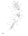
- FIG. 2 shows the components of the removable blind fastener of the present invention.
- a first member 10 is provided having an elongate cylindrical hollow body 11 with a countersink head 12 at one end of body 11.
- the first member 10 is fabricated by direct laser metal sintering (DLMS), which is a rapid prototyping technique, whereby a CAD file representing the first member 10 is used to control a laser which fuses metal powder into a solid body.
- the metal is maraging steel.
- the outer surface of the first member 10 is polished using an ultrasound polishing technique in order to remove any imperfections which may damage the work-piece to be clamped by the fastener 1.
- DLMS direct laser metal sintering
- the outer diameter of the first member 10 is determined by the diameter of the hole in the work-piece into which it is to be inserted. Therefore a range of fasteners are provided to fit a range of holes sizes. In this example the fastener is intended to fit a 1 ⁇ 4" (0.635 cm) hole.
- the first member 10 acts as a dowel to peg two work-pieces together and hence to ensure alignment of the work-pieces, and as such the outer diameter of the first member 10 should be equal to, or slightly less than, the diameter of the hole, for a snug fit.
- the wall of the first member 10 must be strong but also thin to allow full flexing of fingers associated with a second member, as discussed below.
- the first member 10 is provided with a chamfer 17, set at an angle of 9°, which assists in locating the fastener within a hole drilled in the work-piece.
- Head 12 has a countersink recess 13 for receiving a screw member 31.
- Four slots 14 are provided in the head 12 which are used to hold the first member 10 stationary in relation to other components of the fastener during use, as discussed below.
- the inside of hollow body 11 is generally "cross-shaped", in that a cross-shaped recess 16 is provided running in an axial direction, to provide four triangular-section protrusions 15A, 15B, 15C, 15D on the inside of the hollow body 11 as locating means.
- a second member 20 is provided for cooperation with the first member 10.
- the second member comprises a body 21 and four flexible fingers 22A, 22B, 22C, 22D .
- the body 21 and the fingers 22A-D are formed as a single unit to avoid the weakness that would arise if these elements were formed separately and then joined.
- the body 21 is formed as a "cross-shape" which corresponds to the cross-shaped recess of the first member 10, and provides four protrusions 21A, 21 B, 21C, 21 D to locate with the triangular-section protrusions 15A-D on the inside of the hollow body 21 of the first member 10.
- the cross-shapes of the telescoping bodies prevent rotation of one body relative to the other.
- the body 21 is provided with a threaded hole 25 in an axial direction suitable for receiving the threaded shank of a screw member 30.
- the four flexible fingers 22A-D are each located at an outer edge of protrusion 21A-D and extend from body 21 away from the threaded hole 25.
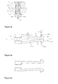
- Figures 5a and 5b show in detail the arrangement of fingers 22A and 22C in relation to the body 21.
- each finger At rest each finger is disposed to converge at a point remote from the body 21, subtending an angle ⁇ between the finger and a central axis X-X'.
- ⁇ 15°.
- Each finger 22A-D has a head 23A,23B,23C,23D at one end remote from the first member 10.
- a cone shape is formed by the four heads 23A-D to pass through an aperture easily.
- the cone shape has a diameter less than the diameter of the cylindrical body 11, i.e. radially within the extremities of the body 11.
- Figure 5a shows in detail heads 23A and 23C associated with fingers 22A and 22C.
- the head 23A has a planar surfaces 24A orientated perpendicularly to the finger 22A. When at rest, the planar surface 24A subtends the same angle ⁇ to a direction perpendicular to the central axis X-X' as the finger 22A subtends to the central axis X-X'.
- planar surface 24A is co-planar with the surface of a work-piece.
- Planar surfaces 24A are clamping surfaces of the fastener and the clamping forces are exerted between these surfaces and the head 12 of the first member 10.
- Planar surfaces 24A-D should be substantially blemish-free so that they do not impart any marking or scoring to the work-piece that they are clamped against.
- the second member 20 may be possible to fabricate the second member 20 as a series of bonded components, but bonded joints in the regions that are subject to high stress would be prone to failure.
- the complex shape of the second member 20 is particularly suited to fabrication using DLMS, where the component is made as a single piece.
- a screw member 30 is provided having a countersunk screw head 31.
- Head 31 has a hexagonal shaped recess 32 so it can be rotated by a hex tool.
- Screw member 30 has a screw shaft 33 which passes through the first member body 11 and engages with the threaded aperture 25 on the second member body 21.
- the end 34 of screw shaft 33 is tapered and smooth.
- the screw is made from 12.9 grade high tensile steel.
- Figure 3 shows a removable blind fastener in an assembled state.
- the cross-shaped body 21 of the second member 20 is inserted into the cross-shaped recess of the first member 10, and the screw member 30 inserted through the head 12 of the first member 10.
- the screw member 30 passes through the first member 10 to engage with the threaded aperture 25 of the second member 20 and the screw turned until the tapered end 34 of the screw member 30 rests against the internal surfaces of the fingers 22A-D.
- work-piece A is aligned with work-piece B.
- Work-pieces may be wing-skins, spars, struts, ribs, runners or stingers, or any combination, not limited to two pieces and may be a stack of three or more pieces.
- the fastener 1 may also pass through the flanges of an I-beam.
- a hole 40a is then drilled between the two work-pieces which may then be reamed to the correct tolerance.
- the hole is then countersunk to leave an aperture 40a as shown in Figure 5a .
- Figure 4b shows a fastener 1 being inserted into the hole 40a, where it can be seen that the heads 23A-D of the second member 30 are narrow enough to pass through hole 40a.
- Figure 5c shows the fastener 1 fully inserted into hole 40a to join the two work-pieces together.
- the head 12 of body 11 engages in the countersink of aperture 40a to engage the face of workpiece A.
- the fastener 1 is a flush fit against the surface of work-piece A and therefore causes no obstruction on the work-piece surface. Therefore the surface of clamped work-pieces, such as a wing section under construction is flat to the same extent as the finished wing section with permanent rivets in place. This allows machinery to move across the surface of the work-pieces unimpeded by temporary clamping fasteners.
- first member 10 The outer surface of first member 10 is a snug fit into the hole 40a and dowels the two work-pieces together to maintain their alignment. It will be seen that the length of the first member 10 should be sufficient to provide an adequate dowelling action between work-piece A and work-piece B and therefore the length of the first member 10 will be determined by the combined thickness of the work-pieces to be joined. Fastener 1 is therefore tailored to suit particular applications. Generally the thickness of the work-pieces will also determine the diameter of the hole 40a and possibly also the spacing of fasteners across the structure being assembled.
- fingers 22A-D travel along the smooth tapered end of the screw shaft 33 opening out as they do so, until they reach the parallel-sided part of screw shaft 33, upon which further travel along the parallel sides of the screw shaft 33 will no longer cause the fingers 22A-D to open outwards.
- the fingers 22A-D should move outwards to their fullest extent before the heads 23A-D engage with the outer face of work-piece B. If this were not to happen then there is a risk that the lateral movement of the heads 23A-D against the surface of the work-piece will cause damage to the surface.
- the fingers 22A-D do not exert any lateral pressure against the side of the hole 40a as they expand, as they are limited from doing so by the body 11 of first member 10. Therefore all of the clamping force exerted by the fastener 1 is in a direction co-axial with the fastener 1, i.e. the forces act to compress the fastener 1 and not to expand the hole 40a.
- Figure 4e shows how further rotation of the screw 30 slides the second member further towards first member 10 so drawing the two work-pieces together so that the planar portions 24A-D fully engage with the face of the work-piece B.
- Clamping loads can be carefully controlled by applying an appropriate torque to the screw member 33 and can range from lightly clamped (i.e. substantially zero load but in contact with the face of the work-piece B) to loads in excess of 2000 Nm.
- Rotation of the screw member 30 in the other direction slides the second member 20 away from the first member and allows the flexible fingers 22A-D to move radially inwards again back into the position shown in Figure 5c. Movement of the fingers 22A-D radially inwards is caused by the resiliency of the material from which they are made. They are biased to return to a closed resting position. Therefore the fingers 22A-D follow the profile of the screw member 33 and as the screw member 33 withdraws relative to the second member 20 the fingers close around the smooth tip. When the fingers are fully closed, fastener 1 can be withdrawn from the aperture 40a in work-pieces A and B.
- fastener can be installed and tightened from one side of work-pieces A and B. This is termed "blind” operation; access to the underside of work-pieces A and B is not required in order to tighten or release the fastener 1.
- the first member 10 may be fabricated from any suitable material such as plastic or metals such as brass, tool steel or stainless steel. The relatively simple construction of this component renders it suitable for fabrication by injection moulding or casting. The outer surface of the first member 10 may be machined to a smooth finish.
- the head 31 of screw member 33 may be of a cap head type as shown in Figure 6a . This allows a larger hex socket to be used and thus a greater torque applied to the screw member 33. The fastener 1 would then project from the surface of the work-piece.
- Other shaped recesses may be provided in the head 31 for driving the screw member 30, such as "Phillips" type or slotted type heads.
- the head 12 of the first member 10 may be of a conventional bolt type, as shown in Figure 6b .
- This provides a greater purchase area for retaining first member 10 as the screw member 33 is rotated.
- Figure 6b shows the use of a cap headed screw member 33 and bolt type headed first member 10, the combination of which provide a large degree of control over the two elements during insertion, tightening and removal of the fastener 1, but present a raised profile above the surface of the work-pieces.
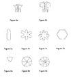
- the internal recess 16 of the first member 10 may have a cross section other than cross-shaped.
- Figure 7a shows a slot-like recess
- Figure 7b shows a recess having six triangular protrusions
- Figure 7c shows a recess having eight triangular protrusions
- Figure 7d shows a recess with hexagonal sides. Other configurations may be envisaged.
- the body 21 of the second member 22 should be shaped so as to fit within the recess 16 provided in the first member 10.
- fingers 22A-D need not be limited to four in number. For instance a single finger, as shown in plan view in Figure 8a , would be adequate to provide a clamping force between work-pieces. Alternatively six ( Figure 8b ), ten ( Figure 8c ) or any other number of fingers could also be used to deliver the clamping force.
- the cone-shaped head of the second member 33 could be cylindrical, as long as it was of a size to fit into the hole 40a in the work-pieces.
- a series of fasteners are envisaged to fit various sized holes. For instance 1/4" (0.635 cm), 5/16" (0.794 cm), 3/8" (0.953 cm), 7/16" (1.111 cm), 1/2" (1.270 cm), 9/16" (1.429 cm), 5/8" (1.588 cm), 3/4" (1.905 cm) etc. Also metric sizes can be provided, e.g. M4, M5 etc. Each sized fastener may be colour coded for ease of identification.
- the first and second member could have two surface such as flat surfaces which lie against each other allowing one to slide against the other, e.g. the first and second member could be abutting two half cylinders.
Landscapes
- Engineering & Computer Science (AREA)
- General Engineering & Computer Science (AREA)
- Mechanical Engineering (AREA)
- Dowels (AREA)
- Connection Of Plates (AREA)
Claims (15)
- Un boulon serti amovible (1) comprenant un premier élément (10) ayant un corps allongé (11) avec une tête (12) à une extrémité, un second élément (20) permettant un mouvement axial par rapport au premier élément (10), le second élément (20) ayant une ouverture filetée (25) et au moins un doigt réglable (22A,B,C,D), le doigt réglable ayant une collerette (23A, B, C, D) éloignée de la tête (12) du premier élément (10) et le doigt étant réglable entre une première et une seconde position dans lesquelles la collerette est au niveau ou à l'intérieur de la circonférence du corps creux du premier élément (10) dans la première position du doigt réglable, et la collerette s'étend au-delà de la circonférence du corps creux du premier élément (10) dans la deuxième position du doigt réglable ; et un élément fileté (30) ayant une tête (31) en forme permettant un engagement avec la tête (12) du premier élément (10) et une tige filetée (33) avec une surface d'engagement du doigt éloignée de la tête (31), caractérisé en ce que le premier élément (10) possède une restriction à son extrémité de tête (12) pour empêcher le retrait du second élément (20) de l'extrémité de la tête (12) du premier élément (10), de telle sorte que le boulon serti amovible (1) comprend une partie du premier élément (10), le second élément (20) et de l'élément fileté (30), grâce à quoi, lors de l'utilisation, l'élément fileté (30) est adapté pour s'étendre à travers la restriction à l'extrémité de la tête (12) du premier élément (10) dans le corps creux du premier élément (10) et à venir en prise avec l'ouverture filetée (25) du second élément (20) et la surface d'engagement du doigt de l'arbre fileté (30) est agencé pour venir en prise avec le doigt réglable du second élément (20) de telle sorte que la rotation de l'élément fileté (30) dans un premier sens provoque un déplacement axial du second élément (20) par rapport au premier élément (10) dans une direction de serrage et le mouvement du doigt réglable dans la direction de sa seconde position alors que la rotation de l'élément fileté (30) dans une seconde direction provoque un déplacement axial du second élément (20) par rapport au premier élément (10) dans une direction de libération et de déplacement du doigt réglable dans la direction de sa première position.
- Un boulon serti amovible selon la revendication 1, caractérisé en ce que le second élément (20) coulisse dans le premier élément (10).
- Un boulon serti amovible selon l'une quelconque des revendications précédentes, caractérisé en ce que l'intérieur du premier élément (10) a une forme non-circulaire et l'extérieur du second élément (20) soit de forme non circulaire correspondante pour empêcher la rotation du second élément (20) à l'intérieur du premier élément (10).
- Un boulon serti amovible selon l'une quelconque des revendications précédentes, caractérisé en ce que au moins deux doigts sont prévus.
- Un boulon serti amovible selon l'une quelconque des revendications précédentes, caractérisé en ce que quatre doigts sont prévus.
- Un boulon serti amovible selon l'une quelconque des revendications précédentes, caractérisé en ce que chaque tête de doigt procure une surface plane (24A, B, C, D) pour venir en prise avec une surface plane de la face d'une pièce à usiner.
- Un boulon serti amovible selon l'une quelconque des revendications précédentes, caractérisé en ce que le premier élément (10) et le second élément (20) forment un corps cylindrique et les têtes (23A, B, C, D) sur les doigts flexibles (22A, B, C, D) sont normalement radiales à l'intérieur des extrémités du corps avant d'être sollicitées vers l'extérieur par la vis.
- Un boulon serti amovible selon l'une quelconque des revendications précédentes, caractérisé en ce que les doigts (22A, B, C, D) sont sollicités vers l'extérieur par l'extrémité de l'arbre (34) de la vis opposés de la tête de vis (31), de telle sorte que l'expansion radiale d'un ou de chaque doigt est terminée avant que le ou chaque doigt vienne en prise avec la face de l'autre pièce.
- Un boulon serti amovible selon l'une quelconque des revendications précédentes, caractérisé en ce que la tête (12) du premier élément est adaptée pour recevoir un outil pour l'empêcher de tourner pendant que ladite tête de vis (31) est en rotation.
- Un boulon serti amovible selon l'une quelconque des revendications précédentes, caractérisé en ce que la surface extérieure du premier élément (10) est polie pour obtenir une liaison coulissante avec un alésage.
- Un boulon serti amovible selon l'une quelconque des revendications précédentes, caractérisé en ce que le premier élément (10) est une cheville pour aligner la pièce à usiner.
- Un boulon serti amovible selon l'une quelconque des revendications précédentes, caractérisé en ce que le premier élément (10) possède une tête fraisée de sorte qu'il puisse s'adapter à niveau avec une surface des pièces.
- Un boulon serti amovible selon l'une quelconque des revendications précédentes, caractérisé en ce que l'élément de vis (30) possède une tête fraisée (31) et le premier élément (10) présente un évidement (13) pour recevoir la tête fraisée (31) de l'élément de vis (30), de sorte que la tête d'élément de vis possède un ajustement de niveau avec le premier élément.
- Un boulon serti amovible selon l'une quelconque des revendications précédentes, caractérisé en ce que la fixation est actionnée à partir d'un côté de pièces à assembler.
- Une méthode d'utilisation d'un boulon serti amovible (1) dans une ouverture de pièces à assembler ensemble dans laquelle le boulon serti amovible comprend un premier élément (10) ayant un corps allongé (11) avec une tête (12) à une extrémité, un deuxième élément ayant un corps allongé s'étendant, et adapté pour coulisser, par rapport au premier élément (10), ledit second élément (20) possédant au moins un doigt flexible (22A, B, C, D) avec une tête de doigt (23A, B, C, D) à une extrémité éloignée du premier élément (10), et un élément de vis (30) ayant une tête de vis (31) adjacente à la tête (12) du premier élément, un arbre de vis (33) qui passe à travers une restriction à l'extrémité de la tête du premier élément (10), dans lequel la restriction empêche le retrait du second élément (20) de l'extrémité de tête du premier élément (10), dans lequel l'élément de vis (30) vient en prise avec une ouverture filetée (25) sur le second élément (20), ladite méthode comprenant ;
l'insertion de l'élément de fixation comprenant le premier élément (10), le second élément (20) et l'élément de vis (30) dans une ouverture dans les pièces de telle sorte que la tête (12) du premier élément (10) soit située contre une face d'une pièce ;
faire tourner l'élément de vis (30) pour solliciter au moins un doigt flexible (22A, B, C, D) radialement vers l'extérieur ;
continuer de faire tourner l'élément de vis (30) pour faire coulisser le deuxième élément (20) en direction du premier élément (10) de telle sorte que la ou les têtes de doigt (23A, B, C, D) du ou de chaque doigt viennent en prise avec une face de la pièce pour assembler les pièces ensemble ;
retirer ensuite l'élément de fixation comprenant le premier élément (10), le second élément (20) et l'élément de vis (30) pour faire coulisser le second élément (20) à distance du premier élément (10) de telle sorte que la ou les têtes de doigt (23A, B, C, D) de chaque doigt se désengagent d'une face de la pièce en permettant aux pièces d'être séparées,
et continuer à faire tourner l'élément de vis (30) pour permettre à au moins un doigt flexible (22A, B, C, D) de se déplacer radialement vers l'intérieur de telle sorte que l'élément de fixation est libre d'être retiré de l'ouverture des pièces.
Applications Claiming Priority (2)
| Application Number | Priority Date | Filing Date | Title |
|---|---|---|---|
| GB0801856A GB2455635B8 (en) | 2008-02-01 | 2008-02-01 | Removable blind fastener |
| PCT/GB2009/000119 WO2009095640A1 (fr) | 2008-02-01 | 2009-01-13 | Boulon serti amovible |
Publications (2)
| Publication Number | Publication Date |
|---|---|
| EP2247862A1 EP2247862A1 (fr) | 2010-11-10 |
| EP2247862B1 true EP2247862B1 (fr) | 2014-09-10 |
Family
ID=39186713
Family Applications (1)
| Application Number | Title | Priority Date | Filing Date |
|---|---|---|---|
| EP09705920.8A Active EP2247862B1 (fr) | 2008-02-01 | 2009-01-13 | Boulon serti amovible |
Country Status (5)
| Country | Link |
|---|---|
| US (1) | US8517650B2 (fr) |
| EP (1) | EP2247862B1 (fr) |
| JP (1) | JP2011511225A (fr) |
| GB (1) | GB2455635B8 (fr) |
| WO (1) | WO2009095640A1 (fr) |
Cited By (1)
| Publication number | Priority date | Publication date | Assignee | Title |
|---|---|---|---|---|
| WO2021064148A1 (fr) | 2019-10-01 | 2021-04-08 | Kwikbolt Limited | Petite fixation |
Families Citing this family (39)
| Publication number | Priority date | Publication date | Assignee | Title |
|---|---|---|---|---|
| GB0721325D0 (en) * | 2007-10-31 | 2007-12-12 | Rolls Royce Plc | fastener arrangements |
| CN102197231B (zh) * | 2008-08-26 | 2016-08-24 | 特拉维斯·麦克卢尔 | 临时紧固件 |
| ES2622205T3 (es) | 2009-03-13 | 2017-07-05 | Centrix Inc. | Sujeción ciega con función de antirotación integrada, sistema y métodos |
| DE202010003093U1 (de) * | 2010-03-02 | 2010-06-17 | Veka Ag | Montageelement für einen Festflügel einer Hebe-Schiebetür und Schiebetürprofilsystem |
| CN102011781B (zh) * | 2010-11-19 | 2016-03-30 | 海尔集团公司 | 一种螺栓结构及其装卸方法 |
| USD688937S1 (en) * | 2011-04-29 | 2013-09-03 | Avdel Uk Limited | Blind fastener |
| BE1020453A3 (nl) * | 2011-12-01 | 2013-10-01 | Unilin Bvba | Meubel en werkwijze voor het vervaardigen van meubels. |
| DE102012203865A1 (de) * | 2012-03-13 | 2013-09-19 | Hilti Aktiengesellschaft | Spreizanker |
| PL223205B1 (pl) * | 2012-07-10 | 2016-10-31 | Koelner Rawlplug Ip Spółka Z Ograniczoną Odpowiedzialnością | Zespół mocujący izolację do muru |
| PL230393B1 (pl) * | 2012-07-13 | 2018-10-31 | Koelner Rawlplug Ip Spolka Z Ograniczona Odpowiedzialnoscia | Zespół mocujący izolację do muru |
| WO2015017002A2 (fr) * | 2013-07-15 | 2015-02-05 | United Technologies Corporation | Interface de montage pour ensemble d'aubes de turbulence destiné à la chambre de combustion d'un moteur à turbine à gaz |
| WO2015130533A1 (fr) | 2014-02-18 | 2015-09-03 | Centrix Llc | Vis d'un seul tenant pour éléments de fixation côté borgne et systèmes à élément à rotation libre, et procédés de fabrication et d'utilisation |
| US9683593B1 (en) | 2014-05-19 | 2017-06-20 | Allfasteners USA, LLC | Step bolt connector assembly |
| DE102014011309A1 (de) * | 2014-08-04 | 2016-02-04 | Bernd Siegmund | Bolzen zum Verspannen aneinander liegender Teile |
| JP5946202B1 (ja) * | 2015-01-07 | 2016-07-05 | 株式会社松永工基 | あと施工アンカー |
| CN107002736B (zh) * | 2015-06-08 | 2019-04-19 | 株式会社白井产业 | 接合构造、接合方法及组装家具 |
| WO2017026575A1 (fr) * | 2015-08-12 | 2017-02-16 | 주식회사 로보로보 | Unité de couplage facile à fixer pour jouet |
| JP6385561B2 (ja) * | 2015-12-21 | 2018-09-05 | スガツネ工業株式会社 | 壁貫通取付け装置 |
| ES2890234T3 (es) * | 2016-02-26 | 2022-01-18 | Centrix Inc | Cuerpos de pinza expansibles con característica antirrotación basada en dedo en sección, abrazaderas, insertos y sistemas de los mismos |
| ES2957889T3 (es) * | 2016-03-17 | 2024-01-29 | Centrix Inc | Elemento de sujeción extraíble de un solo lado con intervalo de agarre de altura de pila ultrabaja y métodos para fabricar y usar el mismo |
| CN105817520B (zh) * | 2016-05-18 | 2017-12-22 | 常州市武进金阳光电子有限公司 | 一种便于安装和拆卸的成型模具 |
| EP3275645A1 (fr) * | 2016-07-25 | 2018-01-31 | nolax AG | Élement sandwich, procede de production d'un element sandwich et son utilisation |
| US10730169B2 (en) | 2017-07-13 | 2020-08-04 | Allfasteners USA, LLC | Tool apparatus including blind bolt and installation tool |
| US11692574B2 (en) | 2017-09-14 | 2023-07-04 | Centrix Inc. | Fastener system |
| FR3071181B1 (fr) | 2017-09-21 | 2020-01-10 | Lisi Aerospace | Douille de fixation pour l'assemblage de structures et fixation associee |
| GB2567243B (en) * | 2017-10-09 | 2020-02-19 | Kwikbolt Ltd | High load Fastener |
| CN108278069A (zh) * | 2018-03-29 | 2018-07-13 | 浙江司贝宁照明电器有限公司 | 一种连接座以及一种包含该连接座的连接组件 |
| US11549538B2 (en) * | 2018-04-12 | 2023-01-10 | Stephen M. Hill | Pressure lock retention fastener |
| CN108953337A (zh) * | 2018-07-26 | 2018-12-07 | 苏州艾酷玛赫设备制造有限公司 | 具有双重膨胀功能的铆钉件 |
| US11225992B2 (en) * | 2018-08-27 | 2022-01-18 | The Boeing Company | Fastening system and methods for use |
| US12595653B1 (en) * | 2018-10-23 | 2026-04-07 | Altenloh, Brinck & Co. Us, Inc. | Sealing wall fastener assembly |
| US11511844B2 (en) | 2019-01-14 | 2022-11-29 | The Boeing Company | Aircraft with rotatably coupled fuselage end cargo door |
| US11732744B2 (en) * | 2019-02-13 | 2023-08-22 | The Boeing Company | Straight shank end screw for foreign-object-debris (FOD) reduction |
| US11781579B1 (en) | 2019-05-28 | 2023-10-10 | Allfasteners USA, LLC | Blind bolt with collapsible shear sleeve assembly |
| ES3031657T3 (en) * | 2019-10-09 | 2025-07-10 | Doka Gmbh | Anchor |
| CN110925284B (zh) * | 2019-12-13 | 2024-08-20 | 广东乐思富科技有限公司 | 膨胀连接件 |
| CN111640540B (zh) * | 2020-06-19 | 2021-09-07 | 北京朝阳隆华电线电缆有限公司 | 一种线束加工辅助装置及其使用方法 |
| US20250092900A1 (en) * | 2023-09-20 | 2025-03-20 | Utah State University Space Dynamics Laboratory | Expanding Dowel Pin |
| USD1074417S1 (en) * | 2023-09-25 | 2025-05-13 | Yangjiang Yugongfang Home Furnishings Co., Ltd | Furniture connector |
Family Cites Families (9)
| Publication number | Priority date | Publication date | Assignee | Title |
|---|---|---|---|---|
| US2379786A (en) * | 1943-10-02 | 1945-07-03 | Bugg | Fastener |
| BE469617A (fr) | 1945-12-03 | |||
| DE3107153A1 (de) | 1981-02-26 | 1982-09-09 | Hans 7341 Amstetten Bäumler | Spreiz- und halteelement |
| US4934885A (en) | 1985-02-25 | 1990-06-19 | The Boeing Company | Tack fastener |
| DE3927529C1 (fr) * | 1989-08-21 | 1991-03-07 | A. Raymond Kg, 7850 Loerrach, De | |
| GB2271143B (en) * | 1992-08-28 | 1995-09-27 | Nifco Inc | Fixing device for sheet member |
| JP3749017B2 (ja) * | 1998-04-03 | 2006-02-22 | 株式会社パイオラックス | 固定クリップ |
| JP4796278B2 (ja) * | 2002-02-15 | 2011-10-19 | マックルアー、トラヴィス | 拡大可能のコレットアンカー装置、その構成要素並びにそれの製造方法及び使用方法 |
| US20040208721A1 (en) * | 2003-04-17 | 2004-10-21 | Rainer Kuenzel | Fastener adapted for use with a structural member |
-
2008
- 2008-02-01 GB GB0801856A patent/GB2455635B8/en active Active
-
2009
- 2009-01-13 JP JP2010544772A patent/JP2011511225A/ja active Pending
- 2009-01-13 US US12/865,111 patent/US8517650B2/en active Active
- 2009-01-13 EP EP09705920.8A patent/EP2247862B1/fr active Active
- 2009-01-13 WO PCT/GB2009/000119 patent/WO2009095640A1/fr not_active Ceased
Cited By (1)
| Publication number | Priority date | Publication date | Assignee | Title |
|---|---|---|---|---|
| WO2021064148A1 (fr) | 2019-10-01 | 2021-04-08 | Kwikbolt Limited | Petite fixation |
Also Published As
| Publication number | Publication date |
|---|---|
| GB2455635B (en) | 2009-11-25 |
| WO2009095640A1 (fr) | 2009-08-06 |
| US8517650B2 (en) | 2013-08-27 |
| US20110008124A1 (en) | 2011-01-13 |
| JP2011511225A (ja) | 2011-04-07 |
| GB0801856D0 (en) | 2008-03-05 |
| GB2455635A (en) | 2009-06-24 |
| GB2455635B8 (en) | 2009-12-09 |
| EP2247862A1 (fr) | 2010-11-10 |
Similar Documents
| Publication | Publication Date | Title |
|---|---|---|
| US8517650B2 (en) | Removable blind fastener | |
| EP3325824B1 (fr) | Dispositif de fixation borgne amovible à tolérance élevée | |
| EP1971784B1 (fr) | Ensemble de fixation | |
| US8152428B2 (en) | Fastener assembly | |
| US5066179A (en) | Blind fastener | |
| JP2002323026A (ja) | ブラインドファスナー、ドライブナット及びファスナー装置の組立て方法 | |
| US6056283A (en) | Tack fastener | |
| US20070253793A1 (en) | Fastener assembly | |
| US20070224014A1 (en) | Fastener for the temporary joinder of parts made of composite material | |
| US20250083214A1 (en) | Fastening systems, fastening system installation apparatus, and methods for fastening | |
| EP3695128A1 (fr) | Fixation à grande capacité de charge | |
| US6755407B1 (en) | Tool clamp and method | |
| US6537004B2 (en) | Blind fastener and drive nut assembly | |
| EP4038286B1 (fr) | Petite fixation | |
| EP0152531A1 (fr) | Rivet aveugle | |
| WO2024126870A1 (fr) | Élément de fixation temporaire avec embrayage | |
| JP2000084757A (ja) | 締結部材ならびに、締結部材のスペーサ部材及び分解方法 |
Legal Events
| Date | Code | Title | Description |
|---|---|---|---|
| PUAI | Public reference made under article 153(3) epc to a published international application that has entered the european phase |
Free format text: ORIGINAL CODE: 0009012 |
|
| 17P | Request for examination filed |
Effective date: 20100825 |
|
| AK | Designated contracting states |
Kind code of ref document: A1 Designated state(s): AT BE BG CH CY CZ DE DK EE ES FI FR GB GR HR HU IE IS IT LI LT LU LV MC MK MT NL NO PL PT RO SE SI SK TR |
|
| AX | Request for extension of the european patent |
Extension state: AL BA RS |
|
| DAX | Request for extension of the european patent (deleted) | ||
| GRAP | Despatch of communication of intention to grant a patent |
Free format text: ORIGINAL CODE: EPIDOSNIGR1 |
|
| INTG | Intention to grant announced |
Effective date: 20140212 |
|
| GRAS | Grant fee paid |
Free format text: ORIGINAL CODE: EPIDOSNIGR3 |
|
| RAP1 | Party data changed (applicant data changed or rights of an application transferred) |
Owner name: KWIKBOLT LIMITED |
|
| RIN1 | Information on inventor provided before grant (corrected) |
Inventor name: NIKLEWICZ, JAN Inventor name: CARRAN, DEAN AINSLEY |
|
| GRAA | (expected) grant |
Free format text: ORIGINAL CODE: 0009210 |
|
| RIN1 | Information on inventor provided before grant (corrected) |
Inventor name: NIKLEWICZ, JAN Inventor name: CARRAN, DEAN AINSLEY |
|
| AK | Designated contracting states |
Kind code of ref document: B1 Designated state(s): AT BE BG CH CY CZ DE DK EE ES FI FR GB GR HR HU IE IS IT LI LT LU LV MC MK MT NL NO PL PT RO SE SI SK TR |
|
| REG | Reference to a national code |
Ref country code: GB Ref legal event code: FG4D |
|
| REG | Reference to a national code |
Ref country code: CH Ref legal event code: EP |
|
| REG | Reference to a national code |
Ref country code: IE Ref legal event code: FG4D |
|
| REG | Reference to a national code |
Ref country code: AT Ref legal event code: REF Ref document number: 686842 Country of ref document: AT Kind code of ref document: T Effective date: 20141015 |
|
| REG | Reference to a national code |
Ref country code: DE Ref legal event code: R096 Ref document number: 602009026571 Country of ref document: DE Effective date: 20141023 |
|
| PG25 | Lapsed in a contracting state [announced via postgrant information from national office to epo] |
Ref country code: LT Free format text: LAPSE BECAUSE OF FAILURE TO SUBMIT A TRANSLATION OF THE DESCRIPTION OR TO PAY THE FEE WITHIN THE PRESCRIBED TIME-LIMIT Effective date: 20140910 Ref country code: GR Free format text: LAPSE BECAUSE OF FAILURE TO SUBMIT A TRANSLATION OF THE DESCRIPTION OR TO PAY THE FEE WITHIN THE PRESCRIBED TIME-LIMIT Effective date: 20141211 Ref country code: SE Free format text: LAPSE BECAUSE OF FAILURE TO SUBMIT A TRANSLATION OF THE DESCRIPTION OR TO PAY THE FEE WITHIN THE PRESCRIBED TIME-LIMIT Effective date: 20140910 Ref country code: NO Free format text: LAPSE BECAUSE OF FAILURE TO SUBMIT A TRANSLATION OF THE DESCRIPTION OR TO PAY THE FEE WITHIN THE PRESCRIBED TIME-LIMIT Effective date: 20141210 Ref country code: FI Free format text: LAPSE BECAUSE OF FAILURE TO SUBMIT A TRANSLATION OF THE DESCRIPTION OR TO PAY THE FEE WITHIN THE PRESCRIBED TIME-LIMIT Effective date: 20140910 Ref country code: ES Free format text: LAPSE BECAUSE OF FAILURE TO SUBMIT A TRANSLATION OF THE DESCRIPTION OR TO PAY THE FEE WITHIN THE PRESCRIBED TIME-LIMIT Effective date: 20140910 |
|
| REG | Reference to a national code |
Ref country code: NL Ref legal event code: VDEP Effective date: 20140910 |
|
| REG | Reference to a national code |
Ref country code: LT Ref legal event code: MG4D |
|
| PG25 | Lapsed in a contracting state [announced via postgrant information from national office to epo] |
Ref country code: CY Free format text: LAPSE BECAUSE OF FAILURE TO SUBMIT A TRANSLATION OF THE DESCRIPTION OR TO PAY THE FEE WITHIN THE PRESCRIBED TIME-LIMIT Effective date: 20140910 Ref country code: HR Free format text: LAPSE BECAUSE OF FAILURE TO SUBMIT A TRANSLATION OF THE DESCRIPTION OR TO PAY THE FEE WITHIN THE PRESCRIBED TIME-LIMIT Effective date: 20140910 Ref country code: LV Free format text: LAPSE BECAUSE OF FAILURE TO SUBMIT A TRANSLATION OF THE DESCRIPTION OR TO PAY THE FEE WITHIN THE PRESCRIBED TIME-LIMIT Effective date: 20140910 |
|
| REG | Reference to a national code |
Ref country code: AT Ref legal event code: MK05 Ref document number: 686842 Country of ref document: AT Kind code of ref document: T Effective date: 20140910 |
|
| PG25 | Lapsed in a contracting state [announced via postgrant information from national office to epo] |
Ref country code: NL Free format text: LAPSE BECAUSE OF FAILURE TO SUBMIT A TRANSLATION OF THE DESCRIPTION OR TO PAY THE FEE WITHIN THE PRESCRIBED TIME-LIMIT Effective date: 20140910 |
|
| PG25 | Lapsed in a contracting state [announced via postgrant information from national office to epo] |
Ref country code: EE Free format text: LAPSE BECAUSE OF FAILURE TO SUBMIT A TRANSLATION OF THE DESCRIPTION OR TO PAY THE FEE WITHIN THE PRESCRIBED TIME-LIMIT Effective date: 20140910 Ref country code: SK Free format text: LAPSE BECAUSE OF FAILURE TO SUBMIT A TRANSLATION OF THE DESCRIPTION OR TO PAY THE FEE WITHIN THE PRESCRIBED TIME-LIMIT Effective date: 20140910 Ref country code: CZ Free format text: LAPSE BECAUSE OF FAILURE TO SUBMIT A TRANSLATION OF THE DESCRIPTION OR TO PAY THE FEE WITHIN THE PRESCRIBED TIME-LIMIT Effective date: 20140910 Ref country code: PT Free format text: LAPSE BECAUSE OF FAILURE TO SUBMIT A TRANSLATION OF THE DESCRIPTION OR TO PAY THE FEE WITHIN THE PRESCRIBED TIME-LIMIT Effective date: 20150112 Ref country code: IS Free format text: LAPSE BECAUSE OF FAILURE TO SUBMIT A TRANSLATION OF THE DESCRIPTION OR TO PAY THE FEE WITHIN THE PRESCRIBED TIME-LIMIT Effective date: 20150110 Ref country code: RO Free format text: LAPSE BECAUSE OF FAILURE TO SUBMIT A TRANSLATION OF THE DESCRIPTION OR TO PAY THE FEE WITHIN THE PRESCRIBED TIME-LIMIT Effective date: 20140910 |
|
| PG25 | Lapsed in a contracting state [announced via postgrant information from national office to epo] |
Ref country code: AT Free format text: LAPSE BECAUSE OF FAILURE TO SUBMIT A TRANSLATION OF THE DESCRIPTION OR TO PAY THE FEE WITHIN THE PRESCRIBED TIME-LIMIT Effective date: 20140910 Ref country code: PL Free format text: LAPSE BECAUSE OF FAILURE TO SUBMIT A TRANSLATION OF THE DESCRIPTION OR TO PAY THE FEE WITHIN THE PRESCRIBED TIME-LIMIT Effective date: 20140910 |
|
| REG | Reference to a national code |
Ref country code: DE Ref legal event code: R097 Ref document number: 602009026571 Country of ref document: DE |
|
| PG25 | Lapsed in a contracting state [announced via postgrant information from national office to epo] |
Ref country code: BE Free format text: LAPSE BECAUSE OF NON-PAYMENT OF DUE FEES Effective date: 20150131 |
|
| PLBE | No opposition filed within time limit |
Free format text: ORIGINAL CODE: 0009261 |
|
| STAA | Information on the status of an ep patent application or granted ep patent |
Free format text: STATUS: NO OPPOSITION FILED WITHIN TIME LIMIT |
|
| PG25 | Lapsed in a contracting state [announced via postgrant information from national office to epo] |
Ref country code: DK Free format text: LAPSE BECAUSE OF FAILURE TO SUBMIT A TRANSLATION OF THE DESCRIPTION OR TO PAY THE FEE WITHIN THE PRESCRIBED TIME-LIMIT Effective date: 20140910 |
|
| 26N | No opposition filed |
Effective date: 20150611 |
|
| REG | Reference to a national code |
Ref country code: CH Ref legal event code: PL |
|
| PG25 | Lapsed in a contracting state [announced via postgrant information from national office to epo] |
Ref country code: LU Free format text: LAPSE BECAUSE OF FAILURE TO SUBMIT A TRANSLATION OF THE DESCRIPTION OR TO PAY THE FEE WITHIN THE PRESCRIBED TIME-LIMIT Effective date: 20150113 Ref country code: IT Free format text: LAPSE BECAUSE OF FAILURE TO SUBMIT A TRANSLATION OF THE DESCRIPTION OR TO PAY THE FEE WITHIN THE PRESCRIBED TIME-LIMIT Effective date: 20140910 |
|
| PG25 | Lapsed in a contracting state [announced via postgrant information from national office to epo] |
Ref country code: MC Free format text: LAPSE BECAUSE OF FAILURE TO SUBMIT A TRANSLATION OF THE DESCRIPTION OR TO PAY THE FEE WITHIN THE PRESCRIBED TIME-LIMIT Effective date: 20140910 |
|
| PG25 | Lapsed in a contracting state [announced via postgrant information from national office to epo] |
Ref country code: LI Free format text: LAPSE BECAUSE OF NON-PAYMENT OF DUE FEES Effective date: 20150131 Ref country code: CH Free format text: LAPSE BECAUSE OF NON-PAYMENT OF DUE FEES Effective date: 20150131 |
|
| REG | Reference to a national code |
Ref country code: IE Ref legal event code: MM4A |
|
| PG25 | Lapsed in a contracting state [announced via postgrant information from national office to epo] |
Ref country code: SI Free format text: LAPSE BECAUSE OF FAILURE TO SUBMIT A TRANSLATION OF THE DESCRIPTION OR TO PAY THE FEE WITHIN THE PRESCRIBED TIME-LIMIT Effective date: 20140910 |
|
| REG | Reference to a national code |
Ref country code: FR Ref legal event code: PLFP Year of fee payment: 8 |
|
| PG25 | Lapsed in a contracting state [announced via postgrant information from national office to epo] |
Ref country code: IE Free format text: LAPSE BECAUSE OF NON-PAYMENT OF DUE FEES Effective date: 20150113 |
|
| PG25 | Lapsed in a contracting state [announced via postgrant information from national office to epo] |
Ref country code: BE Free format text: LAPSE BECAUSE OF FAILURE TO SUBMIT A TRANSLATION OF THE DESCRIPTION OR TO PAY THE FEE WITHIN THE PRESCRIBED TIME-LIMIT Effective date: 20140910 |
|
| PG25 | Lapsed in a contracting state [announced via postgrant information from national office to epo] |
Ref country code: MT Free format text: LAPSE BECAUSE OF FAILURE TO SUBMIT A TRANSLATION OF THE DESCRIPTION OR TO PAY THE FEE WITHIN THE PRESCRIBED TIME-LIMIT Effective date: 20140910 |
|
| REG | Reference to a national code |
Ref country code: FR Ref legal event code: PLFP Year of fee payment: 9 |
|
| PG25 | Lapsed in a contracting state [announced via postgrant information from national office to epo] |
Ref country code: BG Free format text: LAPSE BECAUSE OF FAILURE TO SUBMIT A TRANSLATION OF THE DESCRIPTION OR TO PAY THE FEE WITHIN THE PRESCRIBED TIME-LIMIT Effective date: 20140910 Ref country code: HU Free format text: LAPSE BECAUSE OF FAILURE TO SUBMIT A TRANSLATION OF THE DESCRIPTION OR TO PAY THE FEE WITHIN THE PRESCRIBED TIME-LIMIT; INVALID AB INITIO Effective date: 20090113 |
|
| PG25 | Lapsed in a contracting state [announced via postgrant information from national office to epo] |
Ref country code: TR Free format text: LAPSE BECAUSE OF FAILURE TO SUBMIT A TRANSLATION OF THE DESCRIPTION OR TO PAY THE FEE WITHIN THE PRESCRIBED TIME-LIMIT Effective date: 20140910 |
|
| REG | Reference to a national code |
Ref country code: FR Ref legal event code: PLFP Year of fee payment: 10 |
|
| PG25 | Lapsed in a contracting state [announced via postgrant information from national office to epo] |
Ref country code: MK Free format text: LAPSE BECAUSE OF FAILURE TO SUBMIT A TRANSLATION OF THE DESCRIPTION OR TO PAY THE FEE WITHIN THE PRESCRIBED TIME-LIMIT Effective date: 20140910 |
|
| REG | Reference to a national code |
Ref country code: GB Ref legal event code: 732E Free format text: REGISTERED BETWEEN 20210902 AND 20210908 |
|
| P01 | Opt-out of the competence of the unified patent court (upc) registered |
Effective date: 20230525 |
|
| PGFP | Annual fee paid to national office [announced via postgrant information from national office to epo] |
Ref country code: GB Payment date: 20251212 Year of fee payment: 18 |
|
| PGFP | Annual fee paid to national office [announced via postgrant information from national office to epo] |
Ref country code: FR Payment date: 20251205 Year of fee payment: 18 |
|
| PGFP | Annual fee paid to national office [announced via postgrant information from national office to epo] |
Ref country code: DE Payment date: 20251217 Year of fee payment: 18 |