EP2247897B1 - Anlage zur produktion von haushalts-warmwasser - Google Patents
Anlage zur produktion von haushalts-warmwasser Download PDFInfo
- Publication number
- EP2247897B1 EP2247897B1 EP20090720206 EP09720206A EP2247897B1 EP 2247897 B1 EP2247897 B1 EP 2247897B1 EP 20090720206 EP20090720206 EP 20090720206 EP 09720206 A EP09720206 A EP 09720206A EP 2247897 B1 EP2247897 B1 EP 2247897B1
- Authority
- EP
- European Patent Office
- Prior art keywords
- boiler
- conduit
- water
- duct
- temperature
- Prior art date
- Legal status (The legal status is an assumption and is not a legal conclusion. Google has not performed a legal analysis and makes no representation as to the accuracy of the status listed.)
- Active
Links
Images


Classifications
-
- F—MECHANICAL ENGINEERING; LIGHTING; HEATING; WEAPONS; BLASTING
- F24—HEATING; RANGES; VENTILATING
- F24D—DOMESTIC- OR SPACE-HEATING SYSTEMS, e.g. CENTRAL HEATING SYSTEMS; DOMESTIC HOT-WATER SUPPLY SYSTEMS; ELEMENTS OR COMPONENTS THEREFOR
- F24D17/00—Domestic hot-water supply systems
- F24D17/0026—Domestic hot-water supply systems with conventional heating means
- F24D17/0031—Domestic hot-water supply systems with conventional heating means with accumulation of the heated water
-
- F—MECHANICAL ENGINEERING; LIGHTING; HEATING; WEAPONS; BLASTING
- F24—HEATING; RANGES; VENTILATING
- F24D—DOMESTIC- OR SPACE-HEATING SYSTEMS, e.g. CENTRAL HEATING SYSTEMS; DOMESTIC HOT-WATER SUPPLY SYSTEMS; ELEMENTS OR COMPONENTS THEREFOR
- F24D19/00—Details
- F24D19/10—Arrangement or mounting of control or safety devices
- F24D19/1006—Arrangement or mounting of control or safety devices for water heating systems
- F24D19/1051—Arrangement or mounting of control or safety devices for water heating systems for domestic hot water
-
- F—MECHANICAL ENGINEERING; LIGHTING; HEATING; WEAPONS; BLASTING
- F24—HEATING; RANGES; VENTILATING
- F24H—FLUID HEATERS, e.g. WATER OR AIR HEATERS, HAVING HEAT-GENERATING MEANS, e.g. HEAT PUMPS, IN GENERAL
- F24H1/00—Water heaters, e.g. boilers, continuous-flow heaters or water-storage heaters
- F24H1/48—Water heaters for central heating incorporating heaters for domestic water
- F24H1/52—Water heaters for central heating incorporating heaters for domestic water incorporating heat exchangers for domestic water
- F24H1/523—Heat exchangers for sanitary water directly heated by the burner
Definitions
- the present invention relates to an installation for producing domestic hot water.
- a sanitary hot water production installation equipping a dwelling both individual and collective, includes a boiler and two exchangers, which will be called one primary, and the other secondary.
- the boiler that for example runs on gas or fuel oil is used to heat a first liquid.
- it may be, in the case of a so-called “mixed” installation, water flowing in the radiators of a central heating system.
- the boiler is equipped with the primary heat exchanger, whose function is to transmit a portion of the heat generated by the hot gases from the combustion of the burner equipping the boiler.
- This boiler is for example of the condensing type, comprising a (or) coil (s) helical (s) (s), for example stainless steel, surrounding the burner, and in which passes the first liquid to be heated.
- a (or) coil (s) helical (s) (s) for example stainless steel
- the first liquid which circulates in closed circuit, can be selected and / or treated, in particular demineralized and degassed so that it does not pose problems related to corrosion and deposition of solids, including limestone -source of clogging, against the walls of the tube (s) of the primary exchanger.
- the flue gases from the burner have for example a temperature of the order of 950 ° C. and the first liquid, initially at ambient temperature, is heated to a temperature of about 80 ° C. ° C.
- the secondary heat exchanger has the function of transmitting heat from the first liquid thus heated to the second liquid, in this case sanitary water, which is used for the purpose of supplying a point of use on demand.
- sanitary water which is used for the purpose of supplying a point of use on demand.
- a sink a sink, a shower and / or a bath for example.
- a secondary exchanger of this kind is described for example in the patent document FR -A-2847972 .
- the temperatures used are considerably lower than in the primary exchanger, so that the passage inside the exchanger of the untreated sanitary water is that is to say, drinking water from the public distribution network does not pose, in principle, a critical problem of corrosion or solid matter deposits.
- Such an installation comprising a boiler and two exchangers generally gives satisfaction in terms of operation, reliability and longevity.
- such a domestic hot water production installation comprises a boiler, a hot water storage tank, a sanitary cold water supply pipe, a water supply boiler feed pipe to be heated, provided with a pump adapted to ensure the circulation of the water to be heated to the boiler when it is started and to prohibit this circulation when it is stopped, a duct for drawing domestic hot water, a duct leaving heated water out of the boiler.
- said sanitary cold water supply duct is connected via a "T" connector, said first connector, on the one hand, to the boiler supply duct and, on the other hand , to a so-called recirculation duct, opening into the lower part of the hot water storage tank, while the boiler outlet duct and the draw duct open respectively in the central portion and in the upper part of the balloon.
- This installation is regulated for example so that the water stored in the flask is kept permanently at a temperature of 65 ° C, which is generally suitable for the applications concerned.
- this cold water is mixed with hot water from the lower part of the flask via the recirculation duct, and it is this mixture (of warm water) that the pump delivers to the water. boiler inlet.
- hot sanitary water at a temperature of 65 ° C, remains stagnant in the pipework upstream of the balloon, including inside the boiler.
- the descent in temperature of this water, in the absence of specific device, is slow.
- the present invention aims to overcome these difficulties by proposing, within an installation of the type mentioned above, both to eliminate -or to all the less significantly reduce the risk of scaling of its pipes while significantly reducing the energy losses that normally occur between successive draws.
- a domestic hot water production system is shown, on the upstream side, on an EFS cold water supply , which may consist of a simple tap for drinking water and, on the downstream side, on a domestic hot water outlet.
- EFS supplying one or more points of use (sink, washbasin, shower, bath, for example).
- the installation comprises a boiler 1 provided with a burner 60 supplied with fuel mixture, for example a gas / air or oil / air mixture by means of a fan 6 with an adjustable flow rate.
- fuel mixture for example a gas / air or oil / air mixture by means of a fan 6 with an adjustable flow rate.
- the function of the installation is to heat the domestic cold water using this boiler, and to maintain the domestic hot water stored, at a given temperature, generally of the order of 65 ° C, in a storage tank. 2 with insulated wall, from where it can be drawn on demand to supply one or more point (s) of use.
- the balloon 2 has a generally cylindrical shape, of vertical axis, with hemispherical end portions, and is supported on the ground by a base 20.
- the burner 60 in the illustrated embodiment, is a cylindrical burner which is surrounded in a helical tubular coil 10 of stainless steel in which the water to be heated passes.
- the assembly is housed in an envelope 11 provided with a flue gas exhaust duct and cooled (not shown), for example connected to a chimney leading to the outside of the house.
- the burned and cooled gases are then evacuated via the sleeve.
- the EFS sanitary cold water inlet into the installation is done by means of a duct 8 having a "T" connection 80 allowing the bifurcation of the water flow either in a duct 30 or in a duct 13.
- the conduit 30 has a portion 3 of substantially enlarged diameter, forming a storage balloon.
- the duct 30 Downstream of the balloon 3, the duct 30 also has a "T" connector 90, which will be conventionally designated “first connector". T ". This authorizes the bifurcation of the flow of water either in a conduit 50, or in a conduit 9, called recirculation.
- the conduit 9 opens through its outlet orifice 900 inside the balloon 2, in the lower part thereof.
- the conduit 50 is provided with an electrically controlled pump 5 and is connected to the inlet of the tubular winding 10 of the boiler 1.
- the output duct 40 of this tubular winding 10 is, in turn, provided with a three-way valve (solenoid valve) 4. On the latter are connected, on the one hand, the aforesaid conduit 13 from the second connector 80 and on the other hand, a conduit 12 which opens out through its outlet orifice 120 inside the balloon 2, in the middle part (approximately mid-height) thereof.
- a three-way valve solenoid valve
- the three-way valve 4 is adapted to be able to selectively connect the outlet duct 40 of the boiler, either with the duct 13 or with the duct 12.
- the DHW outlet duct or draw-off duct 7, leaves via an inlet orifice 70 in the upper part of the flask 2.
- a conventional purge system 21 In the lower part of the balloon 2 is mounted a conventional purge system 21.
- This installation also comprises three temperature probes, namely one T 2 which captures the temperature of the water conveyed by the duct 40, at the outlet of the boiler, another T 1 which captures the temperature of the present water. in the lower portion of the balloon 2, at a level above the orifice 900 (but below the orifice 120) the one at which said re-circulation duct 9 opens and the third T 3 which captures the temperature of the water present in the upper portion of the balloon 2 near the inlet 70 of the drawing duct 7.
- the capacity (volumetric capacity) of the balloon 3 is substantially equal to that of the accumulated ducts 9, 50, 10, 40, 13, 12, and 30 (except balloon).
- this capacity is about 161.
- the figure 1 illustrates the control and automated management of the installation.
- the installation comprises an electronic control unit UEC, in which predetermined operating instructions have been introduced by an operator (heating engineer and / or user). These include the optimal flow of the pump 5, the power used in the boiler 1, and the DHW outlet temperature of the DHW.
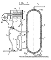
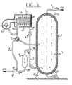
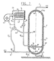
- the UEC will be able to control, according to a given program, the start or stop and the flow rate of the pump 5, the start or stop of the boiler 1 and its power (function of the flow rate of the fan 6), as well as the change of state of the valve 4, this by implementing a process which will now be described with reference to the Figures 3 to 6 .
- Boiler 1 is on (fan 6 on and burner 60 on).
- the valve 4 is thus oriented that the conduits 40 and 12 are in communication, while the conduit 13 is isolated.
- the pump 5 is also running, and is set to provide sufficient flow for proper operation of the boiler, even for a low flow rate i 2 .
- the flow rate of the pump 5 is independent of the flow rate.
- a flow of hot water i 2 thus leaves the balloon through the upper orifice 70 of the balloon 2 and passes into the conduit 7.
- an identical flow of cold water i 1 arrives in the installation via the conduit 8. It can not enter the conduit 13 whose other end is closed (valve 4 closed) and therefore enters completely into the conduit 30 and the balloon 3, to come out via the first connector 90, and supply the pump 5. It is then mixed at a flow i 3 which leaves the base of the balloon 2 by the recirculation duct 9.
- This mixture is heated to a temperature of 65 ° C., controlled by the probe T 2 and is distributed in the central portion of the flask 2 via the conduit 12 (arrows j ).
- This hot water is distributed inside the storage tank 2 by providing some mixing and homogenization of the temperature as a fraction i 2 out of the top and another i 3 out of the bottom.
- the UEC keeps the pump 5 and the boiler 1 running without changing the position of the valve 4.
- the pump 5 is kept running.
- the cold water contained in the balloon 3 very quickly causes the cooling of the boiler winding 10, and the mixture of the cold water supplied by the balloon 3 with the hot water dose-volume substantially equivalent-which was in the piping implemented here results in an intermediate final temperature, of the order of 35 to 40 ° C.
- the UEC controls the stopping of the pump 5.
- the water present in the ducts is thus at a temperature too low for the limestone to be deposited on the walls of these ducts at the risk of scaling, in accordance with the desired objective.
- the balloon 2 In the absence of drawing, the balloon 2 remains isolated and the hot water it contains remains at the set temperature, for example 65 ° C.
- the UEC can be programmed so that in case of "small draws”, corresponding to low flow rates and / or short periods of demand for domestic hot water, the system remains in the previous state: boiler 1 off, pump 5 stopped and valve 4 in the bypass position.
- the incoming cold water passes through the conduit 30, expels the intermediate-temperature water which occupies this conduit, including the balloon 3, and the mixture is discharged through the bypass duct 9 at the base of the balloon 2.
- the UEC commands the restarting of the boiler, and returns the installation to its initial operating state corresponding to that of the figure 2 previously described.
- This embodiment differs essentially from the previous one in that the storage balloon - here designated 3'- is not separated here from the storage tank - here designated 2'-, but in integral form.
- the balloon 3 occupies the internal volume of the hemispherical bottom cap of the balloon 2' and is separated from the internal volume of the latter by a horizontal partition 22.
- the conduit 8 for supplying cold water opens directly into the tank 3 'via an outlet orifice 810.
- the first "T” connector here designated 91, is positioned inside the storage tank 2 '.
- the UEC initially keeps the pump 5 and the boiler 1 running, without changing the position of the valve 4. Hot water is then brewed. , with circulation in closed circuit, the going to the boiler being through the ducts 93 and 50, and the return to the flask through the ducts 40 and 12.
- the balloon 3 ' filled with cold water, remains isolated .
- the probe T 2 regulates the power of the burner, which decreases as the temperature rises in the balloon 2 '.
- the UEC controls the stopping of the burner 60.
- the cold water contained in the balloon 3 'very quickly causes the cooling of the boiler winding 10, to achieve an intermediate final temperature, of the order of 35 to 40 ° C.
- the UEC then controls, by a time delay, the stopping of the pump 5.
- the water present in the ducts is thus at a temperature too low for the limestone to be deposited on the walls of these ducts at the risk of scaling, in accordance with the desired objective.
- the flask 2 In the absence of drawing, the flask 2 'remains isolated and the hot water it contains remains at the set temperature, for example 65 ° C.
- the UEC can be programmed so that in case of "small draws", corresponding to low flow rates and / or short periods of demand for domestic hot water, the system remains in the system. previous state (boiler off, pump off and valve in bypass position).
- the sanitary cold water flow entering through the orifice 810 of the duct 8 is the same as that of hot water leaving the flask 2 through the orifice 70 of the duct 7.
- the incoming cold water expels the intermediate-temperature water which occupies the balloon conduit 3 ', and the mixture is discharged through the tubes 910 and 92 of the connector 91 to be diffused at the base of the balloon 2.
- the UEC controls the restarting of the boiler, and returns the installation to its normal initial operating state.
Landscapes
- Engineering & Computer Science (AREA)
- Physics & Mathematics (AREA)
- Thermal Sciences (AREA)
- Chemical & Material Sciences (AREA)
- Combustion & Propulsion (AREA)
- Mechanical Engineering (AREA)
- General Engineering & Computer Science (AREA)
- Heat-Pump Type And Storage Water Heaters (AREA)
- Devices That Are Associated With Refrigeration Equipment (AREA)
- Sorption Type Refrigeration Machines (AREA)
- Bakery Products And Manufacturing Methods Therefor (AREA)
Claims (9)
- Einrichtung zur Erzeugung von Brauchwarmwasser, die einen Heizkessel (1), einen Ballon zur Speicherung warmen Wassers (2; 2'), eine Zuführleitung für Brauchkaltwasser (EFS), eine Leitung (50) zur Versorgung des Heizkessels mit zu erwärmendem Wasser, die mit einer Pumpe (5) ausgestattet ist, die ausgelegt ist, um die Zirkulation des zu erwärmenden Wassers in Richtung des Heizkessels sicherzustellen, wenn sie hochgefahren ist, und diese Zirkulation zu verbieten, wenn sie angehalten ist, eine Leitung (7) zum Zapfen von Brauchwarmwasser (ECS), eine Leitung (40, 12) zum Ausführen erwärmten Wassers aus dem Heizkessel (1), wobei die Leitung (8) zum Zuführen von Brauchkaltwasser (EFS) sich mittels eines T-Verbinders (90; 91), genannt erster Verbinder, einerseits in die Heizkesselversorgungsleitung (50) verzweigt und, andererseits, in eine Leitung (9; 92), genannt Rezirkulationsleitung, die in den unteren Teil des Speicherballons für warmes Wassers (2; 2') mündet, während die Ausgangsleitung des Heizkessels (40, 12) und die Zapfleitung (7) in den mittleren Teil bzw. den oberen Teil dieses Ballons (2; 2') münden,
dadurch gekennzeichnet, dass:- die Leitung (8) zum Zuführen von Brauchkaltwasser (EFS) mit einem zweiten Verbinder (80) in T-Form ausgestattet ist, der stromaufwärts des ersten T-Verbinders (90, 91) platziert ist, wenn man die Zirkulationsrichtung des Kaltbrauchwassers (EFS) berücksichtigt;- der Teil (30) der Zuführleitung für Brauchkaltwasser (EFS), der den zweiten und ersten T-Verbinder (80; 90) verbindet, mit einem kleinen Speicherballon (3; 3') ausgestattet ist, dessen Kapazität deutlich kleiner als die des Speicherballons für warmes Wasser (2; 2') ist;- die Leitung (40) für das Ausführen erwärmten Wassers aus dem Heizkessel mit einem Dreiwegventil (4) ausgestattet ist, das über eine Bypass-Leitung (13) mit dem zweiten T-Verbinder (80) verbunden ist, wobei dieses Ventil (4) wahlweise entweder eine Position, genannt primäre, in der sie den Ausgang des Heizkessels (40) mit dem Mittelteil des Ballons (2; 2') kommunizieren lässt, oder eine Position, genannt sekundäre, in der sie den Ausgang des Heizkessels (40) mit dieser Bypass-Leitung (13) kommunizieren lässt, einnehmen kann. - Einrichtung gemäß Anspruch 1, dadurch gekennzeichnet, dass der Heizkessel (1) ein Gas- oder Heizölkessel ist.
- Einrichtung gemäß Anspruch 2, dadurch gekennzeichnet, dass der Heizkessel (1) einen Gas- oder Heizölbrenner (60) umfasst, der ausgelegt ist, Wasser zu erwärmen, das in einer Rohrwicklung (10) aus rostfrelem Stahl zirkuliert, die den Brenner (60) umringt.
- Einrichtung gemäß einem der Ansprüche 1 bis 3, dadurch gekennzeichnet, dass die Kapazität des kleinen Speicherballons (3; 3') ungefähr gleich der Kapazität der Gesamtheit des Rohrsystems ist, das den Speicherballon (2; 2') versorgt, stromabwärts des zweiten Verbinders in T-Form (80), wobei diese die den Heizkessel (1) durchfliessende Kapazität einschliesst.
- Einrichtung gemäß einem der Ansprüche 1 bis 4, dadurch gekennzeichnet, dass der kleine Ballon (3) unabhängig vom Speicherballon (2) ist und außerhalb von Ihm liegt.
- Einrichtung gemäß einem der Ansprüche 1 bis 4, dadurch gekennzeichnet, dass der kleine Ballon (3') ein Abteil des Speicherballons (2') darstellt und in seinem unteren Teil gelegen ist.
- Einrichtung gemäß einem der Ansprüche 1 bis 4, dadurch gekennzeichnet, dass das Ventil (4) ein Magnetventil ist.
- Einrichtung gemäß Anspruch 7, dadurch gekennzeichnet, dass sie wenigstens drei Temperatursensoren umfasst, die ausgelegt sind, die Temperatur des Wassers, das dort zirkuliert, zu messen, nämlich:- einen Sensor (T1), der die Temperatur im Inneren des Speicherballons (2, 2') in seinem unteren Teil erfasst, aber auf einer Höhe oberhalb davon, wo die Rezirkulationsleitung (9; 92) einmündet;- einen Sensor (T2), der die Temperatur am Ausgang des Heizkessels (1) erfasst;- einen Sensor (T3), der die Temperatur Im Inneren des Speicherballons (2; 2') In seinem oberen Teil in der Nähe des Eingangs (70) der Zapfleltung (7) erfasst.
- Einrichtung gemäß Anspruch 8, dadurch gekennzeichnet, dass sie mit einer Steuer- und Regelungsschaltung ausgestattet ist, die eine Kontrolleinheit (UEC) umfasst, die ausgelegt ist, den Betrieb oder das Anhalten des Heizkessels (1) und der Pumpe (5) zu steuern und das Ventil (4) in Abhängigkeit von Temperatursignalen, die ihm von den Temperatursensoren (T1, T2, T3) bereitgestellt werden, gemäß einem festgelegten Betriebsprogramm zu steuern.
Applications Claiming Priority (2)
| Application Number | Priority Date | Filing Date | Title |
|---|---|---|---|
| FR0851465A FR2928442B1 (fr) | 2008-03-06 | 2008-03-06 | Installation de production d'eau chaude sanitaire |
| PCT/EP2009/052401 WO2009112385A1 (fr) | 2008-03-06 | 2009-02-27 | Installation de production d'eau chaude sanitaire |
Publications (2)
| Publication Number | Publication Date |
|---|---|
| EP2247897A1 EP2247897A1 (de) | 2010-11-10 |
| EP2247897B1 true EP2247897B1 (de) | 2011-07-13 |
Family
ID=39764860
Family Applications (1)
| Application Number | Title | Priority Date | Filing Date |
|---|---|---|---|
| EP20090720206 Active EP2247897B1 (de) | 2008-03-06 | 2009-02-27 | Anlage zur produktion von haushalts-warmwasser |
Country Status (10)
| Country | Link |
|---|---|
| US (1) | US9134037B2 (de) |
| EP (1) | EP2247897B1 (de) |
| JP (1) | JP5206798B2 (de) |
| KR (1) | KR101447251B1 (de) |
| CN (1) | CN101965485B (de) |
| AT (1) | ATE516469T1 (de) |
| CA (1) | CA2713733C (de) |
| FR (1) | FR2928442B1 (de) |
| RU (1) | RU2454609C2 (de) |
| WO (1) | WO2009112385A1 (de) |
Families Citing this family (10)
| Publication number | Priority date | Publication date | Assignee | Title |
|---|---|---|---|---|
| RU2499958C1 (ru) * | 2010-10-21 | 2013-11-27 | Кюндон Уан Корпорейшн | Способ для регулирования температуры горячей воды посредством работы циркуляционного насоса |
| ITVR20110178A1 (it) * | 2011-09-16 | 2013-03-17 | Renato Montini | Bollitore per il riscaldamento di acqua sanitaria |
| US20130074786A1 (en) * | 2011-09-26 | 2013-03-28 | Claude Lesage | Gas water heater with increased thermal efficiency and safety |
| US10260775B2 (en) * | 2013-03-15 | 2019-04-16 | Green Matters Technologies Inc. | Retrofit hot water system and method |
| JP6786045B2 (ja) * | 2016-06-28 | 2020-11-18 | 三浦工業株式会社 | 燃料電池システム |
| US10352587B2 (en) * | 2016-08-25 | 2019-07-16 | Haier Us Appliance Solutions, Inc. | Water heater distribution tube |
| WO2019198006A1 (en) * | 2018-04-11 | 2019-10-17 | Savi Jessica | Heating group |
| IT202000013645A1 (it) | 2020-06-08 | 2021-12-08 | H2Ot S R L | Sistema per il riscaldamento di un liquido comprendente una caldaia ad alto rendimento ed un ottimizzatore |
| IT202100019859A1 (it) * | 2021-07-26 | 2023-01-26 | Cordivari S R L | Sistema di scambio termico per il riscaldamento o il raffreddamento e la stratificazione termica di un fluido e relativo metodo per la stratificazione termica di un fluido. |
| PL4382818T3 (pl) * | 2022-12-06 | 2026-02-02 | Ariston S.P.A. | Zasobnikowy podgrzewacz wody wyposażony w co najmniej jeden pomocniczy element grzejny i kanał obejściowy |
Family Cites Families (86)
| Publication number | Priority date | Publication date | Assignee | Title |
|---|---|---|---|---|
| US2079419A (en) * | 1933-10-09 | 1937-05-04 | Servel Inc | Refrigeration |
| US2515652A (en) * | 1949-02-28 | 1950-07-18 | Reconstruction Finance Corp | Steam system control unit |
| NL135023C (de) * | 1958-03-13 | |||
| US3177659A (en) * | 1962-08-02 | 1965-04-13 | Westinghouse Electric Corp | Heat exchange apparatus |
| US3522909A (en) * | 1968-06-26 | 1970-08-04 | Clayton Manufacturing Co | Instantaneous high-impact fluid jet cleaning systems |
| US3645420A (en) * | 1969-06-23 | 1972-02-29 | Joseph G Machado | High-pressure hot water cleaner |
| US3705574A (en) * | 1971-07-09 | 1972-12-12 | Smith Corp A O | Water heating and storage system with mixing valve |
| US3929154A (en) * | 1974-07-29 | 1975-12-30 | Frank E Goodwin | Freeze protection apparatus |
| US4046320A (en) * | 1975-05-02 | 1977-09-06 | Johnson William A | Fireplace boiler heating system for hot water type furnaces |
| US4096039A (en) * | 1975-12-18 | 1978-06-20 | Carnine Corporation | Condition sensing control system for desalinator automation |
| AU509901B2 (en) * | 1976-04-29 | 1980-05-29 | University Of Melbourne, The | Solar heat-pump |
| US4102752A (en) * | 1976-07-09 | 1978-07-25 | Rugh Ii John L | Municipal water supply system |
| FR2398976A1 (fr) * | 1977-07-25 | 1979-02-23 | Saunier Duval | Dispositif pour la production d'eau chaude sanitaire a partir d'un reservoir d'accumulation et d'un generateur individuel |
| US4155506A (en) * | 1977-11-11 | 1979-05-22 | Tekram Associates | Method and apparatus for conservation of energy in a hot water heating system |
| US4175698A (en) * | 1977-11-11 | 1979-11-27 | Tekram Associates, Inc. | Method and apparatus for conservation of energy in a hot water heating system |
| DK145108C (da) * | 1978-06-22 | 1983-01-31 | Krueger As I | Fremgangsmaade ved udnyttelse af varmeindhold i spildevand samt anlaeg til udoevelse af fremgangsmaaden |
| US4363221A (en) * | 1979-08-20 | 1982-12-14 | Singh Kanwal N | Water heating system having a heat pump |
| US4281519A (en) * | 1979-10-25 | 1981-08-04 | Carrier Corporation | Refrigeration circuit heat reclaim method and apparatus |
| FR2484061B1 (fr) * | 1980-06-04 | 1986-01-31 | Picchiottino Andre | Installation de chauffage notamment pour le chauffage de locaux et pour la production d'eau chaude sanitaire |
| US4412526A (en) * | 1981-01-16 | 1983-11-01 | Degrose Louis | Water tempering system |
| US4438881A (en) * | 1981-01-27 | 1984-03-27 | Pendergrass Joseph C | Solar assisted heat pump heating system |
| US6866092B1 (en) * | 1981-02-19 | 2005-03-15 | Stephen Molivadas | Two-phase heat-transfer systems |
| US4408960A (en) * | 1981-09-11 | 1983-10-11 | Logic Devices, Inc. | Pneumatic method and apparatus for circulating liquids |
| US4374506A (en) * | 1981-09-18 | 1983-02-22 | Whalen Daniel A | Automatic flue gas heat recovery system |
| EP0183328A3 (de) * | 1982-10-29 | 1986-10-01 | JAKOBSSON, Leif | Wärmespeicher |
| IT1183737B (it) * | 1984-02-15 | 1987-10-22 | Silvano Cappi | Abbattitore di fumi per gruppi bruciatore-caldaia a combustibile gassoso o liquido |
| CA1219545A (en) * | 1984-12-06 | 1987-03-24 | Glen Sundquist | Water heater and distiller apparatus |
| JPS61295460A (ja) * | 1985-06-21 | 1986-12-26 | Sanyo Electric Co Ltd | 給湯装置 |
| US4743194A (en) * | 1987-03-13 | 1988-05-10 | Texaco Inc. | Cooling system for gasifier burner operating in a high pressure environment |
| JPH03241263A (ja) * | 1990-02-15 | 1991-10-28 | Gastar Corp | 瞬間式給湯器 |
| US5262013A (en) * | 1991-07-17 | 1993-11-16 | Amalgamated Technologies, Inc. | Coolant recycling method and apparatus |
| US5174123A (en) * | 1991-08-23 | 1992-12-29 | Thermo King Corporation | Methods and apparatus for operating a refrigeration system |
| US5441606A (en) * | 1992-03-23 | 1995-08-15 | Fsr Patented Technologies, Ltd. | Liquid purifying and vacuum distillation process |
| US5396812A (en) * | 1992-06-09 | 1995-03-14 | Peterson; Roger | Sample system |
| US5281309A (en) * | 1992-06-23 | 1994-01-25 | Market Design & Development, Inc. | Portable water purification system |
| US5233970A (en) * | 1992-07-02 | 1993-08-10 | Harmony Thermal Company, Inc. | Semi-instantaneous water heater with helical heat exchanger |
| US5256313A (en) * | 1992-12-21 | 1993-10-26 | Heritage Environmental Services, Inc. | System and process for treatment of cyanide-containing waste |
| FR2700608B1 (fr) | 1993-01-15 | 1995-04-07 | Joseph Le Mer | Elément échangeur de chaleur, procédé et dispositif pour le fabriquer. |
| JP2975276B2 (ja) * | 1994-11-16 | 1999-11-10 | ベスト工業株式会社 | 生物濾過装置用浮上濾材の洗浄方法 |
| US5662779A (en) * | 1995-02-16 | 1997-09-02 | Market Design & Development, Inc. | Portable water purification apparatus |
| US5535596A (en) * | 1995-07-31 | 1996-07-16 | Todack; James J. | Refrigerant reclamation and purification apparatus and method |
| FR2742849B1 (fr) * | 1995-12-26 | 1998-02-27 | Sdecc | Procede de distribution d'eau chaude sanitaire a partir d'une chaudiere a gaz, par l'intermediaire d'un ballon d'accumulation et dispositif de mise en oeuvre du procede |
| JPH10300226A (ja) * | 1997-04-24 | 1998-11-13 | Miura Co Ltd | 貯湯式温水ボイラ |
| RU2124916C1 (ru) * | 1997-05-06 | 1999-01-20 | Попов Сергей Анатольевич | Способ работы установки для перегонки жидкого продукта и установка для его реализации |
| KR19980024976U (ko) * | 1998-04-17 | 1998-07-25 | 이현수 | 열매를 이용한 이중관식 전기가열기 |
| US6275655B1 (en) * | 1998-05-29 | 2001-08-14 | James M. Rixen | Heating system for potable water and relatively small areas |
| US5881952A (en) * | 1998-07-14 | 1999-03-16 | Macintyre; Kenneth R. | Heater for liquids |
| US6604376B1 (en) * | 1999-01-08 | 2003-08-12 | Victor M. Demarco | Heat pump using treated water effluent |
| DE19932436C2 (de) * | 1999-07-12 | 2002-02-28 | Gewofag Gemeinnuetzige Wohnung | Trinkwarmwasserleitungsanlage |
| US6251279B1 (en) * | 1999-12-09 | 2001-06-26 | Dialysis Systems, Inc. | Heat disinfection of a water supply |
| US6564757B2 (en) * | 2000-06-22 | 2003-05-20 | Toyota Jidosha Kabushiki Kaisha | Internal combustion engine including heat accumulation system, and heat carrier supply control system |
| EP1363858B1 (de) * | 2001-02-20 | 2004-09-15 | Watercryst chemiefreie Wasserbehandlung GmbH | Einrichtung zur chemisch/physikalischen wasserbehandlung und trinkwasser |
| JP4493231B2 (ja) * | 2001-03-30 | 2010-06-30 | 東京瓦斯株式会社 | 熱媒循環式加熱装置 |
| ES2264719T4 (es) * | 2001-09-04 | 2007-06-16 | Vittorio Tacchi | Aparato de almacenamiento de calor por termosifon. |
| US6830661B1 (en) * | 2001-10-02 | 2004-12-14 | Environmental Technology Enterprises, L.L.C. | Point of use water purification method and apparatus |
| US20070272539A1 (en) * | 2002-03-04 | 2007-11-29 | Environmental Technology Enterprises, L.L.C. | Point-of-use water purification method and apparatus |
| CN1183357C (zh) * | 2002-04-10 | 2005-01-05 | 沈阳三义自动控制有限责任公司 | 一种供暖管网防窃水方法及其处理装置 |
| FR2843189B1 (fr) * | 2002-07-30 | 2004-10-15 | Mer Joseph Le | "echangeur de chaleur a condensation a double faisceau de tubes" |
| JP2005539191A (ja) * | 2002-09-16 | 2005-12-22 | オルライン サステイナブル テクノロジーズ ピーティーワイ リミテッド | 給湯装置 |
| CA2502526C (fr) | 2002-10-16 | 2010-11-30 | Societe D'etude Et De Realisation Mecaniques Engeneering En Technologies Avancees | Echangeur de chaleur a condensation, a enveloppe plastique |
| FR2847972B1 (fr) | 2002-11-29 | 2005-03-04 | Realisation Mecaniques Engenee | Echangeur de chaleur et dispositif de production d'eau chaude sanitaire |
| FR2854229A1 (fr) * | 2003-04-25 | 2004-10-29 | Realisation Mecaniques Engenee | Echangeur de chaleur a condensation |
| FR2855766A1 (fr) * | 2003-06-06 | 2004-12-10 | Third Millenium Water Company | Procedes et appareils de distillation notamment pour produire de l'eau douce |
| US6977047B2 (en) * | 2003-09-15 | 2005-12-20 | Mechanical Equipment Company, Inc. | Method and system for the manufacture of pharmaceutical water |
| US8377279B2 (en) * | 2003-11-13 | 2013-02-19 | Siemens Industry, Inc. | Water treatment system and method |
| NL1025321C2 (nl) * | 2004-01-24 | 2005-07-27 | Arie Kroon | Systeem en werkwijze voor het verwarmen van tapwater. |
| JP4222215B2 (ja) * | 2004-01-27 | 2009-02-12 | 株式会社デンソー | 貯湯式給湯装置 |
| US20060054305A1 (en) * | 2004-09-14 | 2006-03-16 | Yongfeng Ye | Heating and refrigerating water device |
| US20060196955A1 (en) * | 2005-03-01 | 2006-09-07 | Bill Moxon | Domestic water pre-heating apparatus and method for a vehicle |
| US7089955B1 (en) * | 2005-07-20 | 2006-08-15 | Komro Sr Grant T | Recreational vehicle low temperature water supply warming system |
| RU49957U1 (ru) * | 2005-08-08 | 2005-12-10 | Зенков Валерий Павлович | Автономная система технологического теплоснабжения |
| US7278379B2 (en) * | 2005-11-14 | 2007-10-09 | Pvi Industries, Llc | Heat exchange system |
| DE102005058570B3 (de) * | 2005-12-08 | 2007-05-24 | Robert Bosch Gmbh | Verfahren zur Warmwasserbereitung mit einem Wärmeerzeuger und einem Schichtladespeicher |
| US20070170273A1 (en) * | 2006-01-10 | 2007-07-26 | Mcillwain Equipment Company, Inc. | System and method for producing on demand high temperature water |
| FR2896856B1 (fr) | 2006-01-30 | 2008-05-16 | Mer Joseph Le | Echangeur de chaleur a condensation |
| US20130075245A1 (en) * | 2009-12-16 | 2013-03-28 | F. Alan Frick | Methods and systems for heating and manipulating fluids |
| US20130125842A1 (en) * | 2009-12-16 | 2013-05-23 | Franklin Alan Frick | Methods and systems for heating and manipulating fluids |
| CN200982707Y (zh) * | 2006-12-07 | 2007-11-28 | 冯光远 | 太阳能热水器中空箱体管道排空及用水量可控制的装置 |
| US7298968B1 (en) * | 2007-01-05 | 2007-11-20 | Rheem Manufacturing Company | Pumpless combination instantaneous/storage water heater system |
| KR101329509B1 (ko) * | 2008-08-04 | 2013-11-13 | 엘지전자 주식회사 | 히트펌프 연동 온수 순환 시스템 및 제어 방법 |
| WO2010019078A1 (en) * | 2008-08-15 | 2010-02-18 | Termoventiler I Ulricehamn Ab | Thermostatic mixing valve for a domestic heating system |
| US8657207B2 (en) * | 2008-08-26 | 2014-02-25 | Lg Electronics Inc. | Hot water circulation system associated with heat pump and method for controlling the same |
| JP2010144938A (ja) * | 2008-12-16 | 2010-07-01 | Mitsubishi Electric Corp | ヒートポンプ給湯装置およびその運転方法 |
| CN202198441U (zh) * | 2011-08-02 | 2012-04-25 | 漳州灿坤实业有限公司 | 一种胶囊咖啡机 |
| KR101379766B1 (ko) * | 2012-05-03 | 2014-04-01 | 주식회사 경동나비엔 | 난방효율을 향상시킨 난방 및 온수의 동시 사용이 가능한 보일러 |
| US20130319348A1 (en) * | 2012-05-31 | 2013-12-05 | Dennis R. Hughes | Water heater having condensing recuperator and dual purpose pump |
-
2008
- 2008-03-06 FR FR0851465A patent/FR2928442B1/fr active Active
-
2009
- 2009-02-27 KR KR20107022396A patent/KR101447251B1/ko active Active
- 2009-02-27 AT AT09720206T patent/ATE516469T1/de not_active IP Right Cessation
- 2009-02-27 JP JP2010549110A patent/JP5206798B2/ja active Active
- 2009-02-27 RU RU2010140792/12A patent/RU2454609C2/ru active
- 2009-02-27 CN CN200980107785XA patent/CN101965485B/zh active Active
- 2009-02-27 EP EP20090720206 patent/EP2247897B1/de active Active
- 2009-02-27 WO PCT/EP2009/052401 patent/WO2009112385A1/fr not_active Ceased
- 2009-02-27 CA CA2713733A patent/CA2713733C/fr active Active
- 2009-02-27 US US12/919,073 patent/US9134037B2/en active Active
Also Published As
| Publication number | Publication date |
|---|---|
| JP2011513692A (ja) | 2011-04-28 |
| CN101965485A (zh) | 2011-02-02 |
| RU2454609C2 (ru) | 2012-06-27 |
| FR2928442B1 (fr) | 2010-12-17 |
| WO2009112385A1 (fr) | 2009-09-17 |
| ATE516469T1 (de) | 2011-07-15 |
| EP2247897A1 (de) | 2010-11-10 |
| JP5206798B2 (ja) | 2013-06-12 |
| KR101447251B1 (ko) | 2014-10-06 |
| CA2713733C (fr) | 2015-07-14 |
| KR20110009100A (ko) | 2011-01-27 |
| CA2713733A1 (fr) | 2009-09-17 |
| FR2928442A1 (fr) | 2009-09-11 |
| RU2010140792A (ru) | 2012-04-20 |
| CN101965485B (zh) | 2013-07-24 |
| US9134037B2 (en) | 2015-09-15 |
| US20110132279A1 (en) | 2011-06-09 |
Similar Documents
| Publication | Publication Date | Title |
|---|---|---|
| EP2247897B1 (de) | Anlage zur produktion von haushalts-warmwasser | |
| EP2700883A1 (de) | Hybridsystem zur sanitären Heißwassererzeugung mit einer Wärmepumpe und einem Heizkessel | |
| EP3517871B1 (de) | Wärmerückgewinnungsvorrichtung | |
| EP0719989B1 (de) | Wandgasheizkessel mit kleinem Brauchwasserspeicher | |
| EP0778450B1 (de) | Geräte zur Erzeugung von warmem Brauchwasser | |
| FR3031575A1 (fr) | Module de transfert thermique avec regulation associee pour systeme thermodynamique de production d'eau chaude sanitaire | |
| EP0793791B1 (de) | Modulares gerät für die heizwasserverteilung und gebäudeheizung | |
| FR3018902A1 (fr) | Installation de production d'eau chaude sanitaire et procede de pilotage de cette installation | |
| EP4124803B1 (de) | Steuerverfahren eines thermodynamischen speicher- und heizsystems | |
| FR2817610A1 (fr) | Circuit de preparation d'eau chaude sanitaire pour un chauffe-eau ou une chaudiere | |
| FR2679631A1 (fr) | Dispositif de production d'eau chaude sanitaire a thermosiphon integre. | |
| EP0117796A1 (de) | Klimaanlage für ein Gebäude | |
| EP0245184A1 (de) | Anlage für Zentralheizung mit zwei Energiequellen und Verfahren zum Betreiben derselben | |
| FR2999687A1 (fr) | Dispositif accumulateur d'eau chaude | |
| EP2655977B1 (de) | Vorrichtung zur erzeugung vom sanitärwarmwasser durch die verwendung von thermischen solarkollektoren mit wasser als betriebsflüssigkeit, die direkt mit einem warwasserspeicher verbunden sind. | |
| EP2947393B1 (de) | Schutzumlauf gegen überhitzungseffekte in einem heisswasserbereitungssystem, und entsprechendes heisswasserbereitungssystem | |
| FR2770621A1 (fr) | Appareil economiseur de fuel et reducteur de gaz polluants | |
| FR3115098A1 (fr) | Appareil de chauffage thermodynamique à régulation optimisée | |
| EP0577606A1 (de) | Heisswassererzeuger für haushalts oder zu heizungswecken | |
| EP2224176A1 (de) | Verbesserte Warmwasseranlage | |
| FR2549582A1 (fr) | Appareil bienergie monobloc pour la production d'eau chaude de chauffage central et d'eau chaude sanitaire | |
| EP1408282A1 (de) | Verfahren und Anlage zur Bereitstellung von Warmwasser mit konstanter Temperatur | |
| FR3004791A1 (fr) | Procede de regulation d'eau chaude sanitaire | |
| FR2980559A1 (fr) | Dispositif pour installation combinee de chauffage par circulation d'eau chaude et de production d'eau chaude sanitaire |
Legal Events
| Date | Code | Title | Description |
|---|---|---|---|
| PUAI | Public reference made under article 153(3) epc to a published international application that has entered the european phase |
Free format text: ORIGINAL CODE: 0009012 |
|
| 17P | Request for examination filed |
Effective date: 20100727 |
|
| AK | Designated contracting states |
Kind code of ref document: A1 Designated state(s): AT BE BG CH CY CZ DE DK EE ES FI FR GB GR HR HU IE IS IT LI LT LU LV MC MK MT NL NO PL PT RO SE SI SK TR |
|
| AX | Request for extension of the european patent |
Extension state: AL BA RS |
|
| GRAP | Despatch of communication of intention to grant a patent |
Free format text: ORIGINAL CODE: EPIDOSNIGR1 |
|
| 111Z | Information provided on other rights and legal means of execution |
Free format text: AT BE BG CH CY CZ DE DK EE ES FI FR GB GR HR HU IE IS IT LT LU LV MC MK MT NL NO PL PT RO SE SI SK TR Effective date: 20110125 |
|
| GRAS | Grant fee paid |
Free format text: ORIGINAL CODE: EPIDOSNIGR3 |
|
| GRAA | (expected) grant |
Free format text: ORIGINAL CODE: 0009210 |
|
| DAX | Request for extension of the european patent (deleted) | ||
| AK | Designated contracting states |
Kind code of ref document: B1 Designated state(s): AT BE BG CH CY CZ DE DK EE ES FI FR GB GR HR HU IE IS IT LI LT LU LV MC MK MT NL NO PL PT RO SE SI SK TR |
|
| REG | Reference to a national code |
Ref country code: GB Ref legal event code: FG4D Free format text: NOT ENGLISH |
|
| REG | Reference to a national code |
Ref country code: CH Ref legal event code: EP |
|
| REG | Reference to a national code |
Ref country code: IE Ref legal event code: FG4D Free format text: LANGUAGE OF EP DOCUMENT: FRENCH |
|
| REG | Reference to a national code |
Ref country code: DE Ref legal event code: R096 Ref document number: 602009001814 Country of ref document: DE Effective date: 20110901 |
|
| REG | Reference to a national code |
Ref country code: NL Ref legal event code: VDEP Effective date: 20110713 |
|
| REG | Reference to a national code |
Ref country code: AT Ref legal event code: MK05 Ref document number: 516469 Country of ref document: AT Kind code of ref document: T Effective date: 20110713 |
|
| PG25 | Lapsed in a contracting state [announced via postgrant information from national office to epo] |
Ref country code: SE Free format text: LAPSE BECAUSE OF FAILURE TO SUBMIT A TRANSLATION OF THE DESCRIPTION OR TO PAY THE FEE WITHIN THE PRESCRIBED TIME-LIMIT Effective date: 20110713 Ref country code: PT Free format text: LAPSE BECAUSE OF FAILURE TO SUBMIT A TRANSLATION OF THE DESCRIPTION OR TO PAY THE FEE WITHIN THE PRESCRIBED TIME-LIMIT Effective date: 20111114 Ref country code: IS Free format text: LAPSE BECAUSE OF FAILURE TO SUBMIT A TRANSLATION OF THE DESCRIPTION OR TO PAY THE FEE WITHIN THE PRESCRIBED TIME-LIMIT Effective date: 20111113 Ref country code: FI Free format text: LAPSE BECAUSE OF FAILURE TO SUBMIT A TRANSLATION OF THE DESCRIPTION OR TO PAY THE FEE WITHIN THE PRESCRIBED TIME-LIMIT Effective date: 20110713 Ref country code: NL Free format text: LAPSE BECAUSE OF FAILURE TO SUBMIT A TRANSLATION OF THE DESCRIPTION OR TO PAY THE FEE WITHIN THE PRESCRIBED TIME-LIMIT Effective date: 20110713 Ref country code: LT Free format text: LAPSE BECAUSE OF FAILURE TO SUBMIT A TRANSLATION OF THE DESCRIPTION OR TO PAY THE FEE WITHIN THE PRESCRIBED TIME-LIMIT Effective date: 20110713 Ref country code: NO Free format text: LAPSE BECAUSE OF FAILURE TO SUBMIT A TRANSLATION OF THE DESCRIPTION OR TO PAY THE FEE WITHIN THE PRESCRIBED TIME-LIMIT Effective date: 20111013 Ref country code: HR Free format text: LAPSE BECAUSE OF FAILURE TO SUBMIT A TRANSLATION OF THE DESCRIPTION OR TO PAY THE FEE WITHIN THE PRESCRIBED TIME-LIMIT Effective date: 20110713 |
|
| REG | Reference to a national code |
Ref country code: IE Ref legal event code: FD4D |
|
| PG25 | Lapsed in a contracting state [announced via postgrant information from national office to epo] |
Ref country code: GR Free format text: LAPSE BECAUSE OF FAILURE TO SUBMIT A TRANSLATION OF THE DESCRIPTION OR TO PAY THE FEE WITHIN THE PRESCRIBED TIME-LIMIT Effective date: 20111014 Ref country code: CY Free format text: LAPSE BECAUSE OF FAILURE TO SUBMIT A TRANSLATION OF THE DESCRIPTION OR TO PAY THE FEE WITHIN THE PRESCRIBED TIME-LIMIT Effective date: 20110713 Ref country code: PL Free format text: LAPSE BECAUSE OF FAILURE TO SUBMIT A TRANSLATION OF THE DESCRIPTION OR TO PAY THE FEE WITHIN THE PRESCRIBED TIME-LIMIT Effective date: 20110713 Ref country code: SI Free format text: LAPSE BECAUSE OF FAILURE TO SUBMIT A TRANSLATION OF THE DESCRIPTION OR TO PAY THE FEE WITHIN THE PRESCRIBED TIME-LIMIT Effective date: 20110713 Ref country code: AT Free format text: LAPSE BECAUSE OF FAILURE TO SUBMIT A TRANSLATION OF THE DESCRIPTION OR TO PAY THE FEE WITHIN THE PRESCRIBED TIME-LIMIT Effective date: 20110713 Ref country code: LV Free format text: LAPSE BECAUSE OF FAILURE TO SUBMIT A TRANSLATION OF THE DESCRIPTION OR TO PAY THE FEE WITHIN THE PRESCRIBED TIME-LIMIT Effective date: 20110713 |
|
| PG25 | Lapsed in a contracting state [announced via postgrant information from national office to epo] |
Ref country code: CZ Free format text: LAPSE BECAUSE OF FAILURE TO SUBMIT A TRANSLATION OF THE DESCRIPTION OR TO PAY THE FEE WITHIN THE PRESCRIBED TIME-LIMIT Effective date: 20110713 Ref country code: SK Free format text: LAPSE BECAUSE OF FAILURE TO SUBMIT A TRANSLATION OF THE DESCRIPTION OR TO PAY THE FEE WITHIN THE PRESCRIBED TIME-LIMIT Effective date: 20110713 Ref country code: IE Free format text: LAPSE BECAUSE OF FAILURE TO SUBMIT A TRANSLATION OF THE DESCRIPTION OR TO PAY THE FEE WITHIN THE PRESCRIBED TIME-LIMIT Effective date: 20110713 |
|
| PLBE | No opposition filed within time limit |
Free format text: ORIGINAL CODE: 0009261 |
|
| STAA | Information on the status of an ep patent application or granted ep patent |
Free format text: STATUS: NO OPPOSITION FILED WITHIN TIME LIMIT |
|
| PG25 | Lapsed in a contracting state [announced via postgrant information from national office to epo] |
Ref country code: RO Free format text: LAPSE BECAUSE OF FAILURE TO SUBMIT A TRANSLATION OF THE DESCRIPTION OR TO PAY THE FEE WITHIN THE PRESCRIBED TIME-LIMIT Effective date: 20110713 Ref country code: EE Free format text: LAPSE BECAUSE OF FAILURE TO SUBMIT A TRANSLATION OF THE DESCRIPTION OR TO PAY THE FEE WITHIN THE PRESCRIBED TIME-LIMIT Effective date: 20110713 |
|
| 26N | No opposition filed |
Effective date: 20120416 |
|
| PG25 | Lapsed in a contracting state [announced via postgrant information from national office to epo] |
Ref country code: DK Free format text: LAPSE BECAUSE OF FAILURE TO SUBMIT A TRANSLATION OF THE DESCRIPTION OR TO PAY THE FEE WITHIN THE PRESCRIBED TIME-LIMIT Effective date: 20110713 |
|
| REG | Reference to a national code |
Ref country code: DE Ref legal event code: R097 Ref document number: 602009001814 Country of ref document: DE Effective date: 20120416 |
|
| BERE | Be: lapsed |
Owner name: GIANNONI FRANCE Effective date: 20120228 |
|
| PG25 | Lapsed in a contracting state [announced via postgrant information from national office to epo] |
Ref country code: MC Free format text: LAPSE BECAUSE OF NON-PAYMENT OF DUE FEES Effective date: 20120229 |
|
| PG25 | Lapsed in a contracting state [announced via postgrant information from national office to epo] |
Ref country code: BE Free format text: LAPSE BECAUSE OF NON-PAYMENT OF DUE FEES Effective date: 20120228 |
|
| PG25 | Lapsed in a contracting state [announced via postgrant information from national office to epo] |
Ref country code: MK Free format text: LAPSE BECAUSE OF FAILURE TO SUBMIT A TRANSLATION OF THE DESCRIPTION OR TO PAY THE FEE WITHIN THE PRESCRIBED TIME-LIMIT Effective date: 20110713 |
|
| PG25 | Lapsed in a contracting state [announced via postgrant information from national office to epo] |
Ref country code: ES Free format text: LAPSE BECAUSE OF FAILURE TO SUBMIT A TRANSLATION OF THE DESCRIPTION OR TO PAY THE FEE WITHIN THE PRESCRIBED TIME-LIMIT Effective date: 20111024 |
|
| PG25 | Lapsed in a contracting state [announced via postgrant information from national office to epo] |
Ref country code: BG Free format text: LAPSE BECAUSE OF FAILURE TO SUBMIT A TRANSLATION OF THE DESCRIPTION OR TO PAY THE FEE WITHIN THE PRESCRIBED TIME-LIMIT Effective date: 20111013 |
|
| PG25 | Lapsed in a contracting state [announced via postgrant information from national office to epo] |
Ref country code: MT Free format text: LAPSE BECAUSE OF FAILURE TO SUBMIT A TRANSLATION OF THE DESCRIPTION OR TO PAY THE FEE WITHIN THE PRESCRIBED TIME-LIMIT Effective date: 20110713 |
|
| REG | Reference to a national code |
Ref country code: CH Ref legal event code: PL |
|
| PG25 | Lapsed in a contracting state [announced via postgrant information from national office to epo] |
Ref country code: CH Free format text: LAPSE BECAUSE OF NON-PAYMENT OF DUE FEES Effective date: 20130228 Ref country code: LI Free format text: LAPSE BECAUSE OF NON-PAYMENT OF DUE FEES Effective date: 20130228 |
|
| PG25 | Lapsed in a contracting state [announced via postgrant information from national office to epo] |
Ref country code: TR Free format text: LAPSE BECAUSE OF FAILURE TO SUBMIT A TRANSLATION OF THE DESCRIPTION OR TO PAY THE FEE WITHIN THE PRESCRIBED TIME-LIMIT Effective date: 20110713 |
|
| PG25 | Lapsed in a contracting state [announced via postgrant information from national office to epo] |
Ref country code: LU Free format text: LAPSE BECAUSE OF NON-PAYMENT OF DUE FEES Effective date: 20120227 |
|
| PG25 | Lapsed in a contracting state [announced via postgrant information from national office to epo] |
Ref country code: HU Free format text: LAPSE BECAUSE OF FAILURE TO SUBMIT A TRANSLATION OF THE DESCRIPTION OR TO PAY THE FEE WITHIN THE PRESCRIBED TIME-LIMIT Effective date: 20090227 |
|
| REG | Reference to a national code |
Ref country code: FR Ref legal event code: CD Owner name: SERMETA, FR Effective date: 20140903 |
|
| REG | Reference to a national code |
Ref country code: FR Ref legal event code: GC Effective date: 20141212 Ref country code: FR Ref legal event code: RG Effective date: 20141212 |
|
| REG | Reference to a national code |
Ref country code: FR Ref legal event code: PLFP Year of fee payment: 8 |
|
| REG | Reference to a national code |
Ref country code: FR Ref legal event code: PLFP Year of fee payment: 9 |
|
| REG | Reference to a national code |
Ref country code: FR Ref legal event code: RG Effective date: 20180108 |
|
| REG | Reference to a national code |
Ref country code: FR Ref legal event code: PLFP Year of fee payment: 10 |
|
| P01 | Opt-out of the competence of the unified patent court (upc) registered |
Effective date: 20230428 |
|
| PGFP | Annual fee paid to national office [announced via postgrant information from national office to epo] |
Ref country code: GB Payment date: 20260219 Year of fee payment: 18 |
|
| PGFP | Annual fee paid to national office [announced via postgrant information from national office to epo] |
Ref country code: DE Payment date: 20260206 Year of fee payment: 18 |
|
| PGFP | Annual fee paid to national office [announced via postgrant information from national office to epo] |
Ref country code: IT Payment date: 20260210 Year of fee payment: 18 |
|
| PGFP | Annual fee paid to national office [announced via postgrant information from national office to epo] |
Ref country code: FR Payment date: 20260114 Year of fee payment: 18 |