EP2248225B1 - Connexion électrique améliorée - Google Patents
Connexion électrique améliorée Download PDFInfo
- Publication number
- EP2248225B1 EP2248225B1 EP09713893.7A EP09713893A EP2248225B1 EP 2248225 B1 EP2248225 B1 EP 2248225B1 EP 09713893 A EP09713893 A EP 09713893A EP 2248225 B1 EP2248225 B1 EP 2248225B1
- Authority
- EP
- European Patent Office
- Prior art keywords
- electrical connection
- tubular body
- connector element
- shaped core
- clamp
- Prior art date
- Legal status (The legal status is an assumption and is not a legal conclusion. Google has not performed a legal analysis and makes no representation as to the accuracy of the status listed.)
- Active
Links
Images






Classifications
-
- H—ELECTRICITY
- H01—ELECTRIC ELEMENTS
- H01R—ELECTRICALLY-CONDUCTIVE CONNECTIONS; STRUCTURAL ASSOCIATIONS OF A PLURALITY OF MUTUALLY-INSULATED ELECTRICAL CONNECTING ELEMENTS; COUPLING DEVICES; CURRENT COLLECTORS
- H01R11/00—Individual connecting elements providing two or more spaced connecting locations for conductive members which are, or may be, thereby interconnected, e.g. end pieces for wires or cables supported by the wire or cable and having means for facilitating electrical connection to some other wire, terminal, or conductive member, blocks of binding posts
- H01R11/11—End pieces or tapping pieces for wires, supported by the wire and for facilitating electrical connection to some other wire, terminal or conductive member
- H01R11/28—End pieces consisting of a ferrule or sleeve
- H01R11/281—End pieces consisting of a ferrule or sleeve for connections to batteries
- H01R11/282—End pieces consisting of a ferrule or sleeve for connections to batteries comprising means for facilitating engagement or disengagement, e.g. quick release terminal
-
- H—ELECTRICITY
- H01—ELECTRIC ELEMENTS
- H01R—ELECTRICALLY-CONDUCTIVE CONNECTIONS; STRUCTURAL ASSOCIATIONS OF A PLURALITY OF MUTUALLY-INSULATED ELECTRICAL CONNECTING ELEMENTS; COUPLING DEVICES; CURRENT COLLECTORS
- H01R11/00—Individual connecting elements providing two or more spaced connecting locations for conductive members which are, or may be, thereby interconnected, e.g. end pieces for wires or cables supported by the wire or cable and having means for facilitating electrical connection to some other wire, terminal, or conductive member, blocks of binding posts
- H01R11/11—End pieces or tapping pieces for wires, supported by the wire and for facilitating electrical connection to some other wire, terminal or conductive member
- H01R11/28—End pieces consisting of a ferrule or sleeve
- H01R11/281—End pieces consisting of a ferrule or sleeve for connections to batteries
- H01R11/287—Intermediate parts between battery post and cable end piece
-
- H—ELECTRICITY
- H01—ELECTRIC ELEMENTS
- H01R—ELECTRICALLY-CONDUCTIVE CONNECTIONS; STRUCTURAL ASSOCIATIONS OF A PLURALITY OF MUTUALLY-INSULATED ELECTRICAL CONNECTING ELEMENTS; COUPLING DEVICES; CURRENT COLLECTORS
- H01R13/00—Details of coupling devices of the kinds covered by groups H01R12/70 or H01R24/00 - H01R33/00
- H01R13/02—Contact members
- H01R13/04—Pins or blades for co-operation with sockets
- H01R13/05—Resilient pins or blades
- H01R13/052—Resilient pins or blades co-operating with sockets having a circular transverse section
-
- H—ELECTRICITY
- H01—ELECTRIC ELEMENTS
- H01R—ELECTRICALLY-CONDUCTIVE CONNECTIONS; STRUCTURAL ASSOCIATIONS OF A PLURALITY OF MUTUALLY-INSULATED ELECTRICAL CONNECTING ELEMENTS; COUPLING DEVICES; CURRENT COLLECTORS
- H01R13/00—Details of coupling devices of the kinds covered by groups H01R12/70 or H01R24/00 - H01R33/00
- H01R13/02—Contact members
- H01R13/10—Sockets for co-operation with pins or blades
- H01R13/11—Resilient sockets
- H01R13/111—Resilient sockets co-operating with pins having a circular transverse section
-
- H—ELECTRICITY
- H01—ELECTRIC ELEMENTS
- H01R—ELECTRICALLY-CONDUCTIVE CONNECTIONS; STRUCTURAL ASSOCIATIONS OF A PLURALITY OF MUTUALLY-INSULATED ELECTRICAL CONNECTING ELEMENTS; COUPLING DEVICES; CURRENT COLLECTORS
- H01R13/00—Details of coupling devices of the kinds covered by groups H01R12/70 or H01R24/00 - H01R33/00
- H01R13/02—Contact members
- H01R13/15—Pins, blades or sockets having separate spring member for producing or increasing contact pressure
- H01R13/187—Pins, blades or sockets having separate spring member for producing or increasing contact pressure with spring member in the socket
-
- H—ELECTRICITY
- H01—ELECTRIC ELEMENTS
- H01R—ELECTRICALLY-CONDUCTIVE CONNECTIONS; STRUCTURAL ASSOCIATIONS OF A PLURALITY OF MUTUALLY-INSULATED ELECTRICAL CONNECTING ELEMENTS; COUPLING DEVICES; CURRENT COLLECTORS
- H01R31/00—Coupling parts supported only by co-operation with counterpart
- H01R31/02—Intermediate parts for distributing energy to two or more circuits in parallel, e.g. splitter
Definitions
- the invention concerns an electrical connection of improved type.
- connection concerns the field of electric wiring and is used especially to connect electrical equipment and devices to the clamps of electric accumulators of the static type, for starting or traction purposes.
- clamps are provided with screw/nut tightening means that serve to fix them to the corresponding terminal of the accumulator and with deformable clips for connection to the wire or wires that feed the various functions of the vehicle.
- connections do not require the removal of the clamp from the accumulator terminal to disconnect the wire, but also in this case the operator has to use apposite tools to loosen the nuts and screws that connect each wire to the corresponding clamp.
- Embodiments are also known, where in order to allow the wires to be connected and disconnected more rapidly, the clamp is provided with a lever locking device for connection to the accumulator terminal.
- the object of the present invention is to overcome all the drawbacks described.
- connection and disconnection of the wire or wires to/from the terminals can be carried out more rapidly compared to the connections of known type.
- connection and disconnection can be carried out rapidly.
- connection that is the subject of the invention makes the connection of the electric wires to the terminals of the accumulator simpler and quicker.
- the possibility to rapidly disconnect the wires from the terminals advantageously increases the safety of the connection in case of emergency. Furthermore, advantageously, any damage to the connection can thus be avoided.
- the reduced effort required for the insertion makes the connection particularly easy to be used by any operator, even if he/she is not an expert.
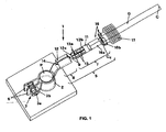
- clamp 2 provided with means 3 for fastening to the terminal P of an electric accumulator and joining means, indicated as a whole by 5, for connection to an electric wire C that connects the clamp 2 to a function.
- the clamp 2 is substantially C-shaped and is provided with projecting tabs 6 featuring flat parallel surfaces and through holes for the insertion of the fastening means 3 that are constituted by a screw 3a which passes through the above mentioned holes and which is associated with a nut 3b.
- the electric wire C is connected to a function which may be an electrical device, for example an electric starter, or the body of the car on which the accumulator is installed.
- the joining means 5 between the electric wire C and the clamp 2 comprise a male connector element 7 and a female connector element 8 that are coupled via contact means 9 with quick coupling and release mechanism.
- the male connector element 7, the female connector element 8 and the contact means 9 with quick coupling and release mechanism are coaxial with one another when they are coupled together.
- the male connector element 7 comprises a shaped core 11 and the female connector element 8 comprises a tubular body 12, and these can be coupled through the above mentioned contact means 9.
- Said contact means 9 comprise a plurality of elastic tabs 13 with curved profile created in the shaped core 11 and the inner surface 14 of the tubular body 12 that oppose each other in order to guarantee electrical continuity and the mechanical connection between the male connector element 7 and the female connector element 8.
- the elastic tabs 13 are parallel to one another and are arranged circumferentially with respect to the longitudinal axis X defined by the shaped core 11 and the curved profile of each one of them has its convex part 13a facing towards the outside of the shaped core 11 to which it belongs in such a way as to be placed in contact with the inner surface 14 of the tubular body 12. Furthermore, each elastic tab 13 has one end 13b that belongs to the shaped core 11 while the opposite end 13c is free, so that each tab 13 behaves like a beam that is constrained at the end 13b and free at the end 13c, which yields elastically at the moment of connection with the corresponding tubular body 12.
- deformable clips 16 comprising first deformable clips 16a for connection to the conductive core Cc of the wire C and second deformable clips 16b for connection to a sleeve 17 arranged outside the insulating sheath G that covers the wire C.
- the electrical connection preferably but not necessarily comprises also a covering 18 made of an insulating material and visible in Figure 5 , which serves to protect the clamp 2 as well as the male connector element 7 and the female connector element 8.
- the sleeve 17 is coupled within the covering 18, thus carrying out a labyrinth seal against the penetration of liquid or solid matter.
- the male connection element 7 is arranged in such a way as to be aligned and coaxial with the female element 8 and spaced from it as shown in Figure 2 .
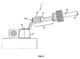
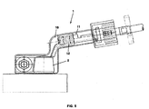
- the male connector element 7 is then moved close to the female connector element 8, as shown in Figure 3 , and the shaped core 11 is forced axially against the tubular body 12.
- the tapered end 11a of the shaped core 11 favours the coupling operation. Once the coupling has taken place, the spontaneous elastic recovery of the tabs 13 causes them to be thrusted against the inner surface 14 of the tubular body 12, thus ensuring electrical continuity and the mechanical connection.
- the disconnection of the connector elements 7 and 8 is also very easy and is achieved by subjecting the male connector element 7 to a traction force that disconnects it from the female connector element 8.
- the male connector element 7 belongs to the wire C and the female connector element 8 belongs to the clamp 2.
- the male connector element 7 may belong to the clamp 2 and the female connector element 8 may belong to the wire C.
- connection indicated as a whole by 20
- the connection differs from the connection just described above only in that the male connector element 7 belongs to the clamp 2 while the female connector element 8 belongs to the wire C.
- connection and disconnection of the male element 7 to/from the female element 8 take place as described above.
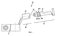
- connection 7 A further construction variant of the connection that is the subject of the invention is shown in Figure 7 , where it is indicated as a whole by 30 and differs from the connection just described due to a different configuration of the contact means 39.
- the elastic tabs 33 created in the shaped core 31 of the male connector element 37 have both ends 33b, 33c belonging to the shaped core 31 and the convex part 33a arranged in a substantially central position and facing outwards.
- the elastic tabs 33 behave like a beam constrained at the ends and curved in the central part which during the pressure coupling with the corresponding tubular body 32 of the female connector element 38 becomes elastically deformed and ensures electrical continuity and the mechanical contact.
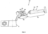
- FIG. 8 A further construction variant of the connection that is an example useful for explaining the invention is shown in Figure 8 , where it is indicated as a whole by 40 and differs from the example just described due to a further different configuration of the contact means 49.
- the elastic tabs 43 have both ends 43b, 43c belonging to the tubular body 42 of the female connector element 48 and are arranged parallel to one another and circumferentially with respect to the longitudinal axis X defined by the tubular body 42.
- the elastic tabs 43 are provided in a tubular sleeve 45 that is forced into the corresponding tubular body 42.
- Both ends 43a and 43b of the elastic tabs 43 belong to the tubular sleeve 45.
- the elastic tabs 43 can be created directly inside the tubular body 42.
- clamp 2 comprises various connector elements, indifferently of the female or male type or even combined, each one of which is coupled with a corresponding connector element belonging to a wire C.
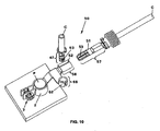
- Figures 9 and 10 show a construction variant of the connection that is the subject of the invention, indicated as a whole by 50, in which it is possible to observe that the clamp 2 comprises two female connector elements 58, 68, each one of which is coupled with a corresponding male connector element 57, 67 belonging to a corresponding wire C.
- each female connector element 58, 68 and each corresponding male connector element 57, 67 are of the type already described and comprise a plurality of elastic tabs 53, 63 with curved profile projecting from the male connector element 57, 67.
- each corresponding tubular body 52, 62 of the female connector element 58, 68 has a cylindrical profile and a substantially smooth surface that is coupled with the elastic tabs 53, 63 to ensure electrical continuity and the mechanical contact.
- FIG. 11 A further construction variant of the connection that is the subject of the invention is shown in Figure 11 , where it is indicated as a whole by 70 and differs from the embodiment just described in that the clamp 2 comprises a female connector element 78 and a male connector element 87, wherein the male connector element 87 is coupled with a corresponding female connector element 88, belonging to the wire C, which includes a tubular body 82.
- the contact means between the male connector element 87 and the female connector element 88 comprise a plurality of shaped projections 84 made on the inner surface of the tubular body 82 parallel to the longitudinal axis X defined by it and the substantially smooth external cylindrical surface 83 of the shaped core 81 of the male connector element 87.
- the coupling takes place through axial shifting and mutual insertion of the connector elements one inside the other.
- FIG. 12 Another construction variant of the invention is shown in Figure 12 , where it is indicated as a whole by 90 and differs from the construction variant described above only in that the male connector element 97 belonging to the clamp 2 is a screw 93 whose thread 93a rests against the shaped projections 94 created on the inner surface of the tubular body 92 belonging to the female connector element 98.
- connection elements of the construction variants comprising several wires connected to the same clamp can be provided with a covering in plastic material 100 in order to ensure protection against oxidation or the penetration of foreign matter in the connection itself, as shown in Figure 14 .
- the elimination of the screw means from the connection allows the operator to connect and disconnect the wire to/from the clamp with no need to use special tools.
- connection that is the subject of the invention makes it possible to connect and disconnect the wire and the clamp in simpler and quicker way and these operations, above all, can be carried out even by unskilled operators.
- the connection that is the subject of the invention thus results to be particularly useful if it is necessary to work in emergency conditions that require the immediate disconnection of the power supply to the various functions.
- the connector elements that create the connection may be subjected to changes that may consist especially of different profiles or shapes of the elements that carry out the mutual electrical connection.
Landscapes
- Details Of Connecting Devices For Male And Female Coupling (AREA)
- Multi-Conductor Connections (AREA)
- Connections By Means Of Piercing Elements, Nuts, Or Screws (AREA)
- Coupling Device And Connection With Printed Circuit (AREA)
Claims (15)
- Connexion électrique (1; 20; 30; 40; 50; 70; 90) comprenant:- une borne (2) dotée de moyens de fixation (3) à la broche (P) d'un accumulateur électrique;- au moins un fil électrique (C) qui relie ladite borne (2) à une ou plusieurs usages;- des moyens de jonction (5) dudit au moins un fil électrique (C) à ladite borne (2), comprenant au moins un élément connecteur mâle (7; 37; 47; 57; 67; 87; 97) et au moins un élément connecteur femelle (8; 38; 48; 58; 68; 88; 98), lesdits éléments connecteurs étant accouplés l'un à l'autre par des moyens de contact (9; 39; 49; 59; 69) avec mécanisme d'accouplement et désaccouplement rapide;où deux ou plusieurs desdits éléments connecteurs (58; 68; 78; 87; 97) appartiennent à ladite borne (2),
caractérisée en ce que lesdits éléments connecteurs (58; 68; 78; 87; 97) appartenant à ladite borne (2) comprennent un élément connecteur femelle (78) et un élément connecteur mâle (87; 97). - Connexion électrique (1; 20; 30; 40; 50; 70; 90) selon la revendication 1), caractérisée en ce que ledit au moins un élément connecteur mâle (7; 37; 47; 57; 67; 87; 97), ledit au moins un élément connecteur femelle (8; 38; 48; 58; 68; 88; 98) et lesdits moyens de contact (9; 39; 49; 59; 69) avec mécanisme d'accouplement et désaccouplement rapide sont coaxiaux entre eux quand ils sont accouplés.
- Connexion électrique (1; 20; 30; 40; 50; 70; 90) selon l'une quelconque des revendications précédentes, caractérisée en ce que ledit au moins un élément connecteur mâle (7; 37; 47; 57; 67; 87; 97) comprend un noyau galbé (11; 31; 41; 81) et ledit au moins un élément connecteur femelle (8; 38; 48; 58; 68; 88; 98) comprend un corps tubulaire (12; 32; 42; 82) qui loge ledit noyau galbé (11; 31; 41; 81), chaque noyau galbé (11; 31; 41; 81) étant accouplé avec un corps tubulaire correspondant (12; 32; 42; 82) par lesdits moyens de contact (9; 39; 49; 59; 69).
- Connexion électrique (1; 20; 30; 50) selon la revendication 3), caractérisée en ce que lesdits moyens de contact (9; 39; 59; 69) comprennent une pluralité de lames élastiques (13; 33; 53; 63) avec profil courbe créées dans ledit noyau galbé (11; 31) et disposées parallèlement à l'axe longitudinal (X) défini par ledit noyau galbé (11; 31), et où lesdites lames élastiques sont appuyées contre la surface intérieure (14; 54; 64) dudit corps tubulaire (12; 32; 42; 82).
- Connexion électrique (1; 20; 30; 50) selon la revendication 4), caractérisée en ce que ledit profil courbe de chacune desdites lames élastiques (13; 33; 53; 63) présente la partie convexe (13a, 33a, 43a) tournée vers l'extérieur dudit noyau galbé (11; 31) auquel elle appartient et en contact avec ladite surface intérieure (14; 54; 64) dudit corps tubulaire (12; 32; 42; 82).
- Connexion électrique (1; 50) selon la revendication 4) ou 5), caractérisée en ce que chacune desdites lames élastiques (13; 33; 53; 63) présente une extrémité (13b) appartenant audit noyau galbé (11; 31), tandis que son extrémité opposée (13a) est libre.
- Connexion électrique (30) selon la revendication 4) ou 5), caractérisée en ce que chacune desdites lames élastiques (33) présente les deux extrémités (33a, 33b) appartenant audit noyau galbé (31).
- Connexion électrique (40) selon la revendication 3), caractérisée en ce que lesdits moyens de contact (49) comprennent une pluralité de lames électriques (43) avec profil courbe créées sur ledit corps tubulaire (42) et disposées parallèlement à l'axe longitudinal (X) défini par ledit corps tubulaire (42), et où lesdites lames élastiques sont appuyées contre la surface extérieure (44) dudit noyau galbé (41).
- Connexion électrique (40) selon la revendication 8), caractérisée en ce que ledit profil courbe de chacune desdites lames élastiques (43) présente la partie convexe (43a) tournée vers l'intérieur dudit corps tubulaire (42) et en contact avec ladite surface extérieure (44) dudit noyau galbé (41).
- Connexion électrique selon la revendication 9), caractérisée en ce que chacune desdites lames électriques (43) avec profil courbe est créée sur ledit corps tubulaire (42) et présente les deux extrémités (43b, 43c) appartenant audit corps tubulaire (42).
- Connexion électrique selon la revendication 9), caractérisée en ce que chacune desdites lames élastiques (43) avec profil courbe est créée dans un manchon tubulaire (45) fixé audit corps tubulaire (42) et présente les deux extrémités (43b, 43c) appartenant audit manchon tubulaire (45).
- Connexion électrique (70) selon la revendication 3), caractérisée en ce que lesdits moyens de contact comprennent une pluralité saillies galbées (84) créées sur la surface intérieure dudit corps tubulaire (82) et disposées parallèlement à l'axe longitudinal (X) défini par ledit corps tubulaire (82), et où lesdites saillies galbées sont appuyées contre la surface cylindrique extérieure (83) dudit noyau galbé (81).
- Connexion électrique selon la revendication 3), caractérisée en ce que lesdits moyens de contact comprennent une pluralité de saillies galbées (94) créées sur la surface intérieure dudit corps tubulaire et disposées parallèlement à l'axe longitudinal (X) défini par ledit corps tubulaire, et où lesdits saillies galbées sont appuyés contre un filet (93a) réalisé sur la surface latérale extérieure dudit noyau galbé.
- Connexion électrique (1; 20; 30; 40; 50) selon l'une quelconque des revendications précédentes, caractérisée en ce que chacun desdits éléments connecteurs (7; 8; 37; 47; 57) appartenant audit fil (C) est doté de griffes déformables (16) pour la connexion audit fil (C).
- Connexion électrique (1; 20; 30; 40; 50) selon la revendication 14), caractérisée en ce que lesdites griffes déformables (16) comprennent de premières griffes déformables (16a) pour la connexion audit noyau conducteur (Cc) dudit fil (C) et de deuxième griffes déformables (16b) pour la connexion à la gaine isolante (G) qui revête ledit noyau conducteur (Cc).
Priority Applications (1)
| Application Number | Priority Date | Filing Date | Title |
|---|---|---|---|
| PL09713893T PL2248225T3 (pl) | 2008-02-28 | 2009-02-26 | Ulepszone połączenie elektryczne |
Applications Claiming Priority (2)
| Application Number | Priority Date | Filing Date | Title |
|---|---|---|---|
| IT000006U ITVI20080006U1 (it) | 2008-02-28 | 2008-02-28 | Connessione elettrica perfezionata |
| PCT/EP2009/052308 WO2009106581A2 (fr) | 2008-02-28 | 2009-02-26 | Connexion électrique améliorée |
Publications (2)
| Publication Number | Publication Date |
|---|---|
| EP2248225A2 EP2248225A2 (fr) | 2010-11-10 |
| EP2248225B1 true EP2248225B1 (fr) | 2013-06-19 |
Family
ID=40292336
Family Applications (1)
| Application Number | Title | Priority Date | Filing Date |
|---|---|---|---|
| EP09713893.7A Active EP2248225B1 (fr) | 2008-02-28 | 2009-02-26 | Connexion électrique améliorée |
Country Status (8)
| Country | Link |
|---|---|
| US (1) | US20110143595A1 (fr) |
| EP (1) | EP2248225B1 (fr) |
| CN (1) | CN101965665A (fr) |
| BR (1) | BRPI0907571B1 (fr) |
| IT (1) | ITVI20080006U1 (fr) |
| PL (1) | PL2248225T3 (fr) |
| RU (1) | RU2010139772A (fr) |
| WO (1) | WO2009106581A2 (fr) |
Families Citing this family (11)
| Publication number | Priority date | Publication date | Assignee | Title |
|---|---|---|---|---|
| EP2589117B1 (fr) * | 2010-06-30 | 2017-11-08 | SABAF S.p.A. | Branchement électrique pour relier un thermocouple à l'ensemble aimant d'un robinet de sécurité d'alimentation en gaz |
| JP5668032B2 (ja) * | 2012-08-22 | 2015-02-12 | トヨタ車体株式会社 | 締結固定具とこれを用いた電源接続構造 |
| CN102916265A (zh) * | 2012-09-29 | 2013-02-06 | 杭州炬华科技股份有限公司 | 带弹性金属套的连接柱 |
| DE102012113123B4 (de) * | 2012-12-27 | 2023-06-01 | Bayerische Motoren Werke Aktiengesellschaft | Erdungsvorrichtung für eine Batterie eines Fahrzeugs |
| ITTO20130598A1 (it) * | 2013-07-16 | 2015-01-17 | Bitron Spa | Dispositivo di carico e/o sicurezza antiallagamento per una macchina di lavaggio. |
| US20170352965A1 (en) * | 2016-06-07 | 2017-12-07 | Royal Die & Stamping Co., Inc. | Jump tab battery terminal clamp |
| DE102017215524A1 (de) * | 2017-09-05 | 2019-03-07 | Robert Bosch Gmbh | Polklemme |
| FR3071367B1 (fr) * | 2017-09-15 | 2020-11-13 | Safran Electrical & Power | Dispositif de liaison electrique dans un aeronef |
| IT201800003963A1 (it) * | 2018-03-26 | 2019-09-26 | Mta Spa | Morsetto per un terminale maschio di una sorgente di energia elettrica. |
| EP3761455B1 (fr) | 2019-07-01 | 2022-06-22 | ODU GmbH & Co. KG | Fiche de connexion avec broche centrale et manchon à lamelle et douille de connexion avec manchon à lamelle |
| KR102651499B1 (ko) * | 2021-08-20 | 2024-03-27 | 현대모비스 주식회사 | 양방향 시그널핀 모듈, 이를 포함한 파워 모듈 및 이의 제조 방법 |
Family Cites Families (26)
| Publication number | Priority date | Publication date | Assignee | Title |
|---|---|---|---|---|
| US1376735A (en) * | 1919-07-08 | 1921-05-03 | Stalhane Otto | Contact-pin for connecting-plugs and process for the manufacture thereof |
| US3369215A (en) * | 1966-02-11 | 1968-02-13 | Clarence B. Haegert | Battery terminal clamp for emergency and/or permanent cable connection |
| US4354726A (en) * | 1979-03-20 | 1982-10-19 | Nissan Motor Company, Limited | Battery terminal connector with an uneven interior surface |
| GB2152298B (en) * | 1983-12-29 | 1988-05-18 | Trw Inc | Multi-leaf electrical contact |
| US4820207A (en) * | 1985-12-31 | 1989-04-11 | Labinal Components And Systems, Inc. | Electrical contact |
| US4740178A (en) * | 1987-09-01 | 1988-04-26 | Vbh Investments (Proprietary) Limited | Battery terminal connection apparatus |
| US5004438A (en) * | 1990-07-03 | 1991-04-02 | Precision Interconnect Corporation | Flexible pin type contact |
| JP2924561B2 (ja) * | 1993-05-25 | 1999-07-26 | 住友電装株式会社 | バッテリー・ターミナル |
| DE4422249A1 (de) * | 1994-06-24 | 1996-02-15 | Temic Bayern Chem Airbag Gmbh | Vorrichtung zum Unterbrechen des Stromflusses in dem Massekabel einer Kraftfahrzeugbatterie |
| DE29516589U1 (de) * | 1995-08-31 | 1995-12-07 | Obligar, Rizal, Quezon City, Metro Manila | Kabelklemme für Batterien |
| DE19620204A1 (de) * | 1996-05-20 | 1997-11-27 | Grote & Hartmann | Anschlußeinrichtung für eine Batterieklemme |
| US5688131A (en) * | 1996-09-03 | 1997-11-18 | Wirth Co Engineering, Inc. | Multi-use electrical connector |
| US5800219A (en) * | 1996-12-17 | 1998-09-01 | United Technologies Automotive, Inc. | Stamped battery terminal |
| JPH1154183A (ja) * | 1997-07-31 | 1999-02-26 | Sumitomo Wiring Syst Ltd | バッテリーターミナル |
| US6062919A (en) * | 1997-08-29 | 2000-05-16 | Thomas & Betts International, Inc. | Electrical connector assembly having high current-carrying capability and low insertion force |
| JP2001291560A (ja) * | 2000-01-17 | 2001-10-19 | Harting Automotive Gmbh & Co Kg | 電路遮断器 |
| US6162098A (en) * | 2000-02-02 | 2000-12-19 | Cheng; Wen Tzung | Modified connector for car battery |
| DE10012387C2 (de) * | 2000-03-14 | 2002-10-02 | Itt Mfg Enterprises Inc | Anordnung zum Verbinden eines Kabels mit einem Kraftfahrzeugbatteriepol |
| JP2004509440A (ja) * | 2000-09-15 | 2004-03-25 | アルコア フジクラ リミテッド | 車両部品用電気的端子ソケット組立体 |
| US6364720B1 (en) * | 2000-12-18 | 2002-04-02 | Shih-Tsung Liang | Battery terminal connector |
| US6459233B1 (en) * | 2001-04-20 | 2002-10-01 | Shih Tsung Liang | Cable attachment assembly for battery of vehicle |
| US6932650B1 (en) * | 2004-03-25 | 2005-08-23 | Royal Die & Stamping Co., Inc. | Fused battery terminal connector |
| FR2881582B1 (fr) * | 2005-02-03 | 2009-03-20 | Tyco Electronics France Sas So | Connecteur pour borne de batterie |
| DE202006001672U1 (de) * | 2006-02-01 | 2007-03-29 | Störring, Harald, Dipl.-Ing. | Vorrichtung zum Anschließen wenigstens einer stromführenden Leitung an einen Batteriepol |
| US7303448B1 (en) * | 2006-05-24 | 2007-12-04 | East Penn Manufacturing Co., Inc. | Battery terminal connector with reversible clamp lever |
| US7549889B2 (en) * | 2007-05-04 | 2009-06-23 | Group Dekko, Inc. | Battery post electrical terminal assembly |
-
2008
- 2008-02-28 IT IT000006U patent/ITVI20080006U1/it unknown
-
2009
- 2009-02-26 PL PL09713893T patent/PL2248225T3/pl unknown
- 2009-02-26 WO PCT/EP2009/052308 patent/WO2009106581A2/fr not_active Ceased
- 2009-02-26 EP EP09713893.7A patent/EP2248225B1/fr active Active
- 2009-02-26 BR BRPI0907571-2A patent/BRPI0907571B1/pt active IP Right Grant
- 2009-02-26 CN CN2009801067186A patent/CN101965665A/zh active Pending
- 2009-02-26 US US12/867,870 patent/US20110143595A1/en not_active Abandoned
- 2009-02-26 RU RU2010139772/07A patent/RU2010139772A/ru not_active Application Discontinuation
Also Published As
| Publication number | Publication date |
|---|---|
| PL2248225T3 (pl) | 2013-11-29 |
| BRPI0907571A2 (pt) | 2016-07-26 |
| EP2248225A2 (fr) | 2010-11-10 |
| BRPI0907571B1 (pt) | 2019-02-12 |
| US20110143595A1 (en) | 2011-06-16 |
| WO2009106581A2 (fr) | 2009-09-03 |
| ITVI20080006U1 (it) | 2009-08-29 |
| WO2009106581A3 (fr) | 2009-10-29 |
| CN101965665A (zh) | 2011-02-02 |
| RU2010139772A (ru) | 2012-04-10 |
Similar Documents
| Publication | Publication Date | Title |
|---|---|---|
| EP2248225B1 (fr) | Connexion électrique améliorée | |
| US7632143B1 (en) | Connector with positive stop and compressible ring for coaxial cable and associated methods | |
| US10505294B2 (en) | Easily assembled coaxial cable and connector with rear body | |
| US7635283B1 (en) | Connector with retaining ring for coaxial cable and associated methods | |
| US4316646A (en) | Laterally flexible electrical connector assembly | |
| US7661984B2 (en) | Locking threaded connection coaxial connector | |
| EP3758177B1 (fr) | Joint de verrouillage de câble de type à compatibilité électromagnétique | |
| KR20110124762A (ko) | 플렉시블 핑거를 포함하는 동축 케이블 커넥터 및 연관된 방법 | |
| CN104221222A (zh) | 用于同轴电缆之快速安装连接器 | |
| KR101143266B1 (ko) | 다심 케이블 전기 접속용 커넥터 | |
| US11855389B2 (en) | Breakaway connectors for coaxial cables | |
| US20120164870A1 (en) | High strength electrical connector | |
| US20120325513A1 (en) | Connector assembly having strain relief feature | |
| JP2009509313A (ja) | 電気コネクタ | |
| US8545256B2 (en) | Electrical connector for use with NATO equipment | |
| US11095072B2 (en) | Coaxial connector having torque-limiting compression ring | |
| US2903672A (en) | Battery terminal connector | |
| HK1153314A (en) | Improved electrical connection | |
| JP3109620U (ja) | プッシュプルロックコネクタ | |
| JP5172396B2 (ja) | 電力ケーブル用プーリングアイ | |
| US9293868B2 (en) | Attachment ring for attaching a shield of a cable to a shell | |
| KR100911084B1 (ko) | 방수 커넥터 | |
| US1160534A (en) | Coupling. | |
| KR101931695B1 (ko) | 캡잭을 이용한 커넥터의 케이블 연결구조 | |
| US20220190519A1 (en) | Electrical connector for a bus bar |
Legal Events
| Date | Code | Title | Description |
|---|---|---|---|
| PUAI | Public reference made under article 153(3) epc to a published international application that has entered the european phase |
Free format text: ORIGINAL CODE: 0009012 |
|
| 17P | Request for examination filed |
Effective date: 20100917 |
|
| AK | Designated contracting states |
Kind code of ref document: A2 Designated state(s): AT BE BG CH CY CZ DE DK EE ES FI FR GB GR HR HU IE IS IT LI LT LU LV MC MK MT NL NO PL PT RO SE SI SK TR |
|
| AX | Request for extension of the european patent |
Extension state: AL BA RS |
|
| DAX | Request for extension of the european patent (deleted) | ||
| GRAP | Despatch of communication of intention to grant a patent |
Free format text: ORIGINAL CODE: EPIDOSNIGR1 |
|
| GRAP | Despatch of communication of intention to grant a patent |
Free format text: ORIGINAL CODE: EPIDOSNIGR1 |
|
| GRAS | Grant fee paid |
Free format text: ORIGINAL CODE: EPIDOSNIGR3 |
|
| GRAA | (expected) grant |
Free format text: ORIGINAL CODE: 0009210 |
|
| AK | Designated contracting states |
Kind code of ref document: B1 Designated state(s): AT BE BG CH CY CZ DE DK EE ES FI FR GB GR HR HU IE IS IT LI LT LU LV MC MK MT NL NO PL PT RO SE SI SK TR |
|
| REG | Reference to a national code |
Ref country code: GB Ref legal event code: FG4D |
|
| REG | Reference to a national code |
Ref country code: CH Ref legal event code: EP |
|
| REG | Reference to a national code |
Ref country code: AT Ref legal event code: REF Ref document number: 618095 Country of ref document: AT Kind code of ref document: T Effective date: 20130715 |
|
| REG | Reference to a national code |
Ref country code: IE Ref legal event code: FG4D |
|
| REG | Reference to a national code |
Ref country code: DE Ref legal event code: R096 Ref document number: 602009016520 Country of ref document: DE Effective date: 20130814 |
|
| PG25 | Lapsed in a contracting state [announced via postgrant information from national office to epo] |
Ref country code: LT Free format text: LAPSE BECAUSE OF FAILURE TO SUBMIT A TRANSLATION OF THE DESCRIPTION OR TO PAY THE FEE WITHIN THE PRESCRIBED TIME-LIMIT Effective date: 20130619 Ref country code: SE Free format text: LAPSE BECAUSE OF FAILURE TO SUBMIT A TRANSLATION OF THE DESCRIPTION OR TO PAY THE FEE WITHIN THE PRESCRIBED TIME-LIMIT Effective date: 20130619 Ref country code: GR Free format text: LAPSE BECAUSE OF FAILURE TO SUBMIT A TRANSLATION OF THE DESCRIPTION OR TO PAY THE FEE WITHIN THE PRESCRIBED TIME-LIMIT Effective date: 20130920 Ref country code: FI Free format text: LAPSE BECAUSE OF FAILURE TO SUBMIT A TRANSLATION OF THE DESCRIPTION OR TO PAY THE FEE WITHIN THE PRESCRIBED TIME-LIMIT Effective date: 20130619 Ref country code: SI Free format text: LAPSE BECAUSE OF FAILURE TO SUBMIT A TRANSLATION OF THE DESCRIPTION OR TO PAY THE FEE WITHIN THE PRESCRIBED TIME-LIMIT Effective date: 20130619 Ref country code: NO Free format text: LAPSE BECAUSE OF FAILURE TO SUBMIT A TRANSLATION OF THE DESCRIPTION OR TO PAY THE FEE WITHIN THE PRESCRIBED TIME-LIMIT Effective date: 20130919 Ref country code: ES Free format text: LAPSE BECAUSE OF FAILURE TO SUBMIT A TRANSLATION OF THE DESCRIPTION OR TO PAY THE FEE WITHIN THE PRESCRIBED TIME-LIMIT Effective date: 20130930 |
|
| REG | Reference to a national code |
Ref country code: AT Ref legal event code: MK05 Ref document number: 618095 Country of ref document: AT Kind code of ref document: T Effective date: 20130619 |
|
| REG | Reference to a national code |
Ref country code: LT Ref legal event code: MG4D |
|
| PG25 | Lapsed in a contracting state [announced via postgrant information from national office to epo] |
Ref country code: HR Free format text: LAPSE BECAUSE OF FAILURE TO SUBMIT A TRANSLATION OF THE DESCRIPTION OR TO PAY THE FEE WITHIN THE PRESCRIBED TIME-LIMIT Effective date: 20130619 Ref country code: BG Free format text: LAPSE BECAUSE OF FAILURE TO SUBMIT A TRANSLATION OF THE DESCRIPTION OR TO PAY THE FEE WITHIN THE PRESCRIBED TIME-LIMIT Effective date: 20130919 |
|
| REG | Reference to a national code |
Ref country code: PL Ref legal event code: T3 |
|
| REG | Reference to a national code |
Ref country code: NL Ref legal event code: VDEP Effective date: 20130619 |
|
| PG25 | Lapsed in a contracting state [announced via postgrant information from national office to epo] |
Ref country code: IT Free format text: LAPSE BECAUSE OF NON-PAYMENT OF DUE FEES Effective date: 20130226 Ref country code: LV Free format text: LAPSE BECAUSE OF FAILURE TO SUBMIT A TRANSLATION OF THE DESCRIPTION OR TO PAY THE FEE WITHIN THE PRESCRIBED TIME-LIMIT Effective date: 20130619 |
|
| PG25 | Lapsed in a contracting state [announced via postgrant information from national office to epo] |
Ref country code: IS Free format text: LAPSE BECAUSE OF FAILURE TO SUBMIT A TRANSLATION OF THE DESCRIPTION OR TO PAY THE FEE WITHIN THE PRESCRIBED TIME-LIMIT Effective date: 20131019 Ref country code: PT Free format text: LAPSE BECAUSE OF FAILURE TO SUBMIT A TRANSLATION OF THE DESCRIPTION OR TO PAY THE FEE WITHIN THE PRESCRIBED TIME-LIMIT Effective date: 20131021 Ref country code: CY Free format text: LAPSE BECAUSE OF FAILURE TO SUBMIT A TRANSLATION OF THE DESCRIPTION OR TO PAY THE FEE WITHIN THE PRESCRIBED TIME-LIMIT Effective date: 20130911 Ref country code: SK Free format text: LAPSE BECAUSE OF FAILURE TO SUBMIT A TRANSLATION OF THE DESCRIPTION OR TO PAY THE FEE WITHIN THE PRESCRIBED TIME-LIMIT Effective date: 20130619 Ref country code: CZ Free format text: LAPSE BECAUSE OF FAILURE TO SUBMIT A TRANSLATION OF THE DESCRIPTION OR TO PAY THE FEE WITHIN THE PRESCRIBED TIME-LIMIT Effective date: 20130619 Ref country code: BE Free format text: LAPSE BECAUSE OF FAILURE TO SUBMIT A TRANSLATION OF THE DESCRIPTION OR TO PAY THE FEE WITHIN THE PRESCRIBED TIME-LIMIT Effective date: 20130619 Ref country code: AT Free format text: LAPSE BECAUSE OF FAILURE TO SUBMIT A TRANSLATION OF THE DESCRIPTION OR TO PAY THE FEE WITHIN THE PRESCRIBED TIME-LIMIT Effective date: 20130619 Ref country code: EE Free format text: LAPSE BECAUSE OF FAILURE TO SUBMIT A TRANSLATION OF THE DESCRIPTION OR TO PAY THE FEE WITHIN THE PRESCRIBED TIME-LIMIT Effective date: 20130619 |
|
| PG25 | Lapsed in a contracting state [announced via postgrant information from national office to epo] |
Ref country code: RO Free format text: LAPSE BECAUSE OF FAILURE TO SUBMIT A TRANSLATION OF THE DESCRIPTION OR TO PAY THE FEE WITHIN THE PRESCRIBED TIME-LIMIT Effective date: 20130619 Ref country code: NL Free format text: LAPSE BECAUSE OF FAILURE TO SUBMIT A TRANSLATION OF THE DESCRIPTION OR TO PAY THE FEE WITHIN THE PRESCRIBED TIME-LIMIT Effective date: 20130619 |
|
| PG25 | Lapsed in a contracting state [announced via postgrant information from national office to epo] |
Ref country code: CY Free format text: LAPSE BECAUSE OF FAILURE TO SUBMIT A TRANSLATION OF THE DESCRIPTION OR TO PAY THE FEE WITHIN THE PRESCRIBED TIME-LIMIT Effective date: 20130619 |
|
| PLBE | No opposition filed within time limit |
Free format text: ORIGINAL CODE: 0009261 |
|
| STAA | Information on the status of an ep patent application or granted ep patent |
Free format text: STATUS: NO OPPOSITION FILED WITHIN TIME LIMIT |
|
| PG25 | Lapsed in a contracting state [announced via postgrant information from national office to epo] |
Ref country code: DK Free format text: LAPSE BECAUSE OF FAILURE TO SUBMIT A TRANSLATION OF THE DESCRIPTION OR TO PAY THE FEE WITHIN THE PRESCRIBED TIME-LIMIT Effective date: 20130619 |
|
| 26N | No opposition filed |
Effective date: 20140320 |
|
| REG | Reference to a national code |
Ref country code: DE Ref legal event code: R097 Ref document number: 602009016520 Country of ref document: DE Effective date: 20140320 |
|
| PG25 | Lapsed in a contracting state [announced via postgrant information from national office to epo] |
Ref country code: LU Free format text: LAPSE BECAUSE OF FAILURE TO SUBMIT A TRANSLATION OF THE DESCRIPTION OR TO PAY THE FEE WITHIN THE PRESCRIBED TIME-LIMIT Effective date: 20140226 Ref country code: MC Free format text: LAPSE BECAUSE OF FAILURE TO SUBMIT A TRANSLATION OF THE DESCRIPTION OR TO PAY THE FEE WITHIN THE PRESCRIBED TIME-LIMIT Effective date: 20130619 |
|
| REG | Reference to a national code |
Ref country code: CH Ref legal event code: PL |
|
| GBPC | Gb: european patent ceased through non-payment of renewal fee |
Effective date: 20140226 |
|
| PG25 | Lapsed in a contracting state [announced via postgrant information from national office to epo] |
Ref country code: LI Free format text: LAPSE BECAUSE OF NON-PAYMENT OF DUE FEES Effective date: 20140228 Ref country code: CH Free format text: LAPSE BECAUSE OF NON-PAYMENT OF DUE FEES Effective date: 20140228 |
|
| REG | Reference to a national code |
Ref country code: IE Ref legal event code: MM4A |
|
| PG25 | Lapsed in a contracting state [announced via postgrant information from national office to epo] |
Ref country code: GB Free format text: LAPSE BECAUSE OF NON-PAYMENT OF DUE FEES Effective date: 20140226 Ref country code: IE Free format text: LAPSE BECAUSE OF NON-PAYMENT OF DUE FEES Effective date: 20140226 |
|
| REG | Reference to a national code |
Ref country code: FR Ref legal event code: PLFP Year of fee payment: 7 |
|
| REG | Reference to a national code |
Ref country code: FR Ref legal event code: PLFP Year of fee payment: 8 |
|
| PG25 | Lapsed in a contracting state [announced via postgrant information from national office to epo] |
Ref country code: MT Free format text: LAPSE BECAUSE OF FAILURE TO SUBMIT A TRANSLATION OF THE DESCRIPTION OR TO PAY THE FEE WITHIN THE PRESCRIBED TIME-LIMIT Effective date: 20130619 |
|
| PG25 | Lapsed in a contracting state [announced via postgrant information from national office to epo] |
Ref country code: HU Free format text: LAPSE BECAUSE OF FAILURE TO SUBMIT A TRANSLATION OF THE DESCRIPTION OR TO PAY THE FEE WITHIN THE PRESCRIBED TIME-LIMIT; INVALID AB INITIO Effective date: 20090226 |
|
| REG | Reference to a national code |
Ref country code: FR Ref legal event code: PLFP Year of fee payment: 9 |
|
| REG | Reference to a national code |
Ref country code: FR Ref legal event code: PLFP Year of fee payment: 10 |
|
| PG25 | Lapsed in a contracting state [announced via postgrant information from national office to epo] |
Ref country code: MK Free format text: LAPSE BECAUSE OF FAILURE TO SUBMIT A TRANSLATION OF THE DESCRIPTION OR TO PAY THE FEE WITHIN THE PRESCRIBED TIME-LIMIT Effective date: 20130619 |
|
| P01 | Opt-out of the competence of the unified patent court (upc) registered |
Effective date: 20230530 |
|
| PGFP | Annual fee paid to national office [announced via postgrant information from national office to epo] |
Ref country code: DE Payment date: 20260218 Year of fee payment: 18 |
|
| PGFP | Annual fee paid to national office [announced via postgrant information from national office to epo] |
Ref country code: IT Payment date: 20251120 Year of fee payment: 18 |
|
| PGFP | Annual fee paid to national office [announced via postgrant information from national office to epo] |
Ref country code: FR Payment date: 20260218 Year of fee payment: 18 |
|
| PGFP | Annual fee paid to national office [announced via postgrant information from national office to epo] |
Ref country code: TR Payment date: 20260218 Year of fee payment: 18 |
|
| PGFP | Annual fee paid to national office [announced via postgrant information from national office to epo] |
Ref country code: PL Payment date: 20260127 Year of fee payment: 18 |