EP2248236B1 - Installation de distribution électrique moyenne ou haute tension - Google Patents
Installation de distribution électrique moyenne ou haute tension Download PDFInfo
- Publication number
- EP2248236B1 EP2248236B1 EP10703251A EP10703251A EP2248236B1 EP 2248236 B1 EP2248236 B1 EP 2248236B1 EP 10703251 A EP10703251 A EP 10703251A EP 10703251 A EP10703251 A EP 10703251A EP 2248236 B1 EP2248236 B1 EP 2248236B1
- Authority
- EP
- European Patent Office
- Prior art keywords
- unit
- housing
- switchgear
- unit according
- low
- Prior art date
- Legal status (The legal status is an assumption and is not a legal conclusion. Google has not performed a legal analysis and makes no representation as to the accuracy of the status listed.)
- Not-in-force
Links
- 238000012423 maintenance Methods 0.000 claims abstract description 8
- 238000007789 sealing Methods 0.000 claims abstract description 4
- 238000003780 insertion Methods 0.000 claims description 19
- 230000037431 insertion Effects 0.000 claims description 19
- 238000000638 solvent extraction Methods 0.000 claims description 4
- 238000006073 displacement reaction Methods 0.000 claims description 2
- 230000008439 repair process Effects 0.000 abstract description 3
- 239000007858 starting material Substances 0.000 description 7
- 230000005405 multipole Effects 0.000 description 4
- 241001136792 Alle Species 0.000 description 2
- RYGMFSIKBFXOCR-UHFFFAOYSA-N Copper Chemical compound [Cu] RYGMFSIKBFXOCR-UHFFFAOYSA-N 0.000 description 2
- 238000007664 blowing Methods 0.000 description 2
- 229910052802 copper Inorganic materials 0.000 description 2
- 239000010949 copper Substances 0.000 description 2
- 238000005516 engineering process Methods 0.000 description 2
- 238000009434 installation Methods 0.000 description 2
- 230000013011 mating Effects 0.000 description 2
- 238000000926 separation method Methods 0.000 description 2
- 210000002023 somite Anatomy 0.000 description 2
- 241000252185 Cobitidae Species 0.000 description 1
- 230000003750 conditioning effect Effects 0.000 description 1
- 230000008878 coupling Effects 0.000 description 1
- 238000010168 coupling process Methods 0.000 description 1
- 238000005859 coupling reaction Methods 0.000 description 1
- 230000005923 long-lasting effect Effects 0.000 description 1
- 230000007257 malfunction Effects 0.000 description 1
- 238000004519 manufacturing process Methods 0.000 description 1
- 238000000034 method Methods 0.000 description 1
- 238000013024 troubleshooting Methods 0.000 description 1
Images


Classifications
-
- H—ELECTRICITY
- H02—GENERATION; CONVERSION OR DISTRIBUTION OF ELECTRIC POWER
- H02B—BOARDS, SUBSTATIONS OR SWITCHING ARRANGEMENTS FOR THE SUPPLY OR DISTRIBUTION OF ELECTRIC POWER
- H02B11/00—Switchgear having carriage withdrawable for isolation
- H02B11/12—Switchgear having carriage withdrawable for isolation with isolation by horizontal withdrawal
- H02B11/167—Switchgear having carriage withdrawable for isolation with isolation by horizontal withdrawal truck type
-
- H—ELECTRICITY
- H02—GENERATION; CONVERSION OR DISTRIBUTION OF ELECTRIC POWER
- H02B—BOARDS, SUBSTATIONS OR SWITCHING ARRANGEMENTS FOR THE SUPPLY OR DISTRIBUTION OF ELECTRIC POWER
- H02B1/00—Frameworks, boards, panels, desks, casings; Details of substations or switching arrangements
- H02B1/26—Casings; Parts thereof or accessories therefor
- H02B1/30—Cabinet-type casings; Parts thereof or accessories therefor
- H02B1/32—Mounting of devices therein
- H02B1/34—Racks
- H02B1/36—Racks with withdrawable units
-
- H—ELECTRICITY
- H02—GENERATION; CONVERSION OR DISTRIBUTION OF ELECTRIC POWER
- H02B—BOARDS, SUBSTATIONS OR SWITCHING ARRANGEMENTS FOR THE SUPPLY OR DISTRIBUTION OF ELECTRIC POWER
- H02B13/00—Arrangement of switchgear in which switches are enclosed in, or structurally associated with, a casing, e.g. cubicle
- H02B13/02—Arrangement of switchgear in which switches are enclosed in, or structurally associated with, a casing, e.g. cubicle with metal casing
- H02B13/025—Safety arrangements, e.g. in case of excessive pressure or fire due to electrical defect
Definitions
- the invention relates to a medium or high voltage switchgear with a system housing, with a low-voltage control part, with a cable connection space, with a busbar system and with a slide-in unit in the system housing and slide-out unit for power parts, wherein the system housing is designed as a front open outer housing and the Plug-in unit is designed such that it is in and out of the plant housing pushed out.
- Medium-voltage switchgear are usually provided with a built-in low-voltage niche in the housing for the respective low-voltage control part.
- the switching or power unit Arranged in the housing below is usually arranged the switching or power unit, which are often designed extendable.
- switchgear include a pressure channel for blowing out the overpressure in case of failure, a busbar area for the production of the electrical contact and supply power to the power units. It is also common to provide a cable connection area or space where the medium or high voltage is fed into the system.
- the connection of the low voltage control part to the customer terminal block is provided via multi-pole cables to connect the customer's control lines to the low voltage part. In the known switchgear these areas are divided according to the same pattern in four separate partitioned areas or cells. The pull-out switching component of these systems offers the advantage of easy maintenance and replacement of this component.
- the classic switchgear as well as off DE 39 27 835 A1 or DE 36 28 113 A1 and DE 25 15 152 A1 are known, have an outer plant housing with door that protects the environment in case of failure.
- the door is arranged on the system housing and closes the system housing with or without inserted plug-in unit in such a way that there is no danger to the environment in the event of a malfunction.
- In the system housing arranged on the door usually also electrical components are present, which have a susceptibility, so if necessary to maintain and replace. During this time, the system can not be used accordingly.
- the object of the present invention therefore is to provide a switchgear that allows quick and easy regular maintenance and fault repair in case of failure for all electrical components.
- the plug-in unit has a permanently installed front door for hermetically closing the opening formed by the plant housing and the insertion part next to the power unit has the low-voltage control part, all system-relevant components are only in the insertion part, so that an exchange of the individual inserts within a very short time and with minimum personnel costs is guaranteed.
- a wide variety of inserts fit into the same system housing, so that there is a modular system. Its configuration can be changed at any time and without any restrictions before, during and after commissioning. Increasing loads, changes in technology, introduction of new technologies, etc., can be covered by replacing the bays by just 5 minutes. This also applies to any electrical components integrated in the door as the door is changed together with the drawer.
- Mean voltage is understood here to mean a voltage between 3 kV and 30 kV.
- high voltage is meant in the present case a voltage between 30 kV and 110 kV.
- Integrated in the front door is thus almost a movable with the insertion part low-voltage niche, which should include the entire controller.
- the power units are medium voltage switching and distribution components.
- the plug-in unit has one or more power units from the following group on the input field, DOL motor starter, soft starters up to 6kV, soft starters up to 12kV, star / delta motor starter, autot rafo motor starter, bypass field for multi motor start, switching network, compensation field.
- the low-voltage control part it makes sense to include the low-voltage control part for space savings and simultaneous optimal placement with its operating and display elements within the power unit. It is preferred if the low voltage part is cut off to the power unit, so that it is protected in case of failure. As usual, the low-voltage control part is also accessible and maintainable in the closed, pushed-in state of the plug-in unit via a flap or door from the front of the front door. Its electrical and control connection takes place via a connection field or connection field arranged in a front side rail of the system housing in order to produce an electrical connection of the low-voltage control part with the customer's control lines.
- the customer control lines are e.g. Coming from the double floor pulled into the side spar and placed there firmly. This connection can remain permanently.
- the soluble connection with the low-voltage control part takes place, then via the multi-pole cable in the manner of a patch panel.
- the connection is automatically unplugged via a suitable arrangement when pushing out the plug-in unit.
- the switchgear with a device for blowing out the overpressure in case of failure.
- this is a pressure channel for connection to an external Ausblasrohrsystem, so that the overpressure is not dissipated in the switch room.
- the plant housing is organizationally in a rear and front Split part.
- the cable connection compartment, the busbar system and the pressure channel form the rear part of the system housing. It is useful if the cable connection part space, the busbar system and the pressure channel are arranged one above the other, wherein the cable connection space can be located at the very bottom and the pressure channel at the top.
- the Jardinan gleichteilraum, the busbar system and the pressure channel are preferably partitioned to each other in the vertical direction.
- This partitioning usefully has flaps opening in the direction of the pressure channel.
- the busbar system is separated into two separate mutually partitioned areas that can be independently powered. These may each be several e.g. have three power distribution rails.
- the first power distribution rails (including the mating contacts for the insertion part) of the first area can cover the base load of the power distribution.
- the second area may e.g. be used to increase the current carrying capacity of the system, a redundant feed, a start sequence for soft starters with multi-motor or a feed for switching networks.
- the busbar areas are provided with skids as usual, in order to be able to separate them from the power section.
- the front part of the plant housing is designed to receive the plug-in unit. It forms a kind of "garage” for the insertion part with a total depth of the slot.
- the garage ensures the protection of the slide-in parts against external influences and ensures the arc stability in conjunction with the front door of the insertion part. It also provides guidance and locking of the slide-in parts along with their front door.
- the plug-in unit preferably comprises a frame-like frame with fixed front door.
- different power components can be attached to the frame.
- the front door in conjunction with the system housing or its front part is an essential safety component. Thus, when locked, the door ensures that persons in front of it remain uninjured in the event of an accident.
- the front door thus has a suitable lock and seal, so that the door is locked in the end position of the insert by operating a lever against the system housing and a hermetic completion of the opening formed by the plant housing is achieved.
- the switchgear thus has a locking mechanism for hermetically closing the opening formed by the plant housing through the front door, which has elements displaceable relative to one another on the front door and the plant housing, of which at least one part is provided with surfaces inclined in a direction perpendicular to the direction of displacement, that when moving the elements against each other for locking the front door is pulled against the system housing.
- the plant housing on the front face several circumferentially palembracede projecting hooks, which reach through the slots of sliding rails of a rail system in the door or their profiles during insertion of the plug-in unit.
- the hook mouths of the hook are in the range of slidable over the locking mechanism slots of the rails that they are moved when locking with their edges in the Hakenmäuler of the individual hooks and engage and thereby provided on a provided in the respective hook mouth oblique edge along slide so as to pull the door against the plant housing.
- both the system housing and the plug-in unit and the door is provided with seals that lie in case of failure in case of sudden pressure increase in the system against the housing and strengthen or improve the tightness. So u.a. exploited that in case of failure in case of sudden pressure increase, the door twisted, so that the inner sides of the adjacent to the plant housing spars lift off this and press the outer sides of this accordingly.
- the insertion part which contains various technical solutions depending on the insertion variant, thus contains all electrotechnically relevant components of the system. This means that virtually all errors occur in the insertion part. This is on wheels or is arranged on a rail system with or without ball bearings and can thus be completely exchanged within a few minutes. Due to the 0% to 100% error distribution of the components, a function after replacing the insert part is guaranteed.
- the system housing as a "base unit” therefore contains no copper-related parts for power distribution (including contact point for the plug-in unit) no electrotechnically relevant parts.
- the error risk of the copper bars is almost 0. This ensures that the basic unit under no circumstances needs to be changed, maintained or repaired after installation.
- the system will remain closed until the medium or high voltage is completely low. That is, before the drawer can be pulled out, first the power contacts and the control contacts must be solved. This ensures that any system error can only take place in the safe closed state. In an emergency, the insert could be exchanged directly and the operation resumed at short notice.
- the plug-in unit can be pulled out and the resulting work can be easily accessed from all sides.
- the separate customer connection area and the low voltage control section allow free access even during operation of the components. Even with concept changes, no power cables or customer control cables need to be relocated.
- the plug-in unit with the aid of a manual or motorized operation between a fully energized operating position, a test position with energization of the low-voltage control part and a completely de-energized maintenance position configured convertible.
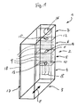
- FIG. 1 a medium-voltage switchgear or her plant housing 1 ( FIG. 1 ) and the associated plug-in unit 20 (FIG. FIG. 2 ) are shown in a schematic perspective view, wherein the plant housing 1 and the insertable and retractable plug-in unit 20 are shown "transparent" for a better understanding.
- the plant housing 1 is formed as a front open outer housing, has a skeleton-like structure with spars and is organisationally divided into a rear part 2 and front part 3.
- a cable connection compartment 4, a busbar system 5, 6 and a pressure channel 7 form the rear part 3 of the system housing 1.
- the cable connection compartment 4, the busbar system 5, 6 and the pressure channel 7 are arranged one above the other in the vertical direction.
- the cable connection space 4 arranged at the bottom serves for feeding in the electrical medium voltage into the switchgear and has for this purpose connection fields 8 in order to apply externally supplied cables or to couple them by means of a plug connection.
- the topmost pressure channel 7 is provided for connection to an external Ausblasrohrsystem and used to blow out the resulting in case of failure overpressure.
- the busbar system arranged in the middle is separated into two separate superimposed areas 5, 6, which can be supplied with power independently of each other. These areas 5, 6 each have three power distribution rails 9.
- the first power distribution rails 9 (including the corresponding ones) can be used Mating contacts for the insertion part) of the first region 5 cover a base load of the energy distribution.
- the second area 6 can be used, for example, for an increase in the current carrying capacity of the system, a redundant feed, a start sequence in the case of a soft starter with a multi-motor or an infeed for coupling fields.
- the JardinanParkraum 4 the busbar sections 5 and 6 and the pressure channel 7 are partitioned to each other in the vertical direction by sheets 10, 11, 12, each having in the direction of the pressure channel 7 opening flaps 13, 14, 15.
- the pressure channel 7 is also separated by a flap 29 from the front part 3.
- the cable connection space 4 is open to the front part 3 of the system housing 1.
- the busbar sections 5 and 6 are provided, as usual, with skids (not shown).
- the front part 3 of the plant housing 1 serves to receive the insertable and retractable plug-in unit 20. This can be in the direction of the arrow E in the plant housing 1 on roles and / or a rail system off or inserted.
- the plug-in unit 20 has a frame-like frame 21 with a fixed front door 22.
- the frame 21 carries the power parts 23.
- the permanently installed front door 22 serves for the hermetic completion of the opening formed by the plant housing 1, so that persons standing in front of the plant in case of failure remain unimpaired.
- the insertion part 20 in addition to the power unit 23 and the low-voltage control part 24, all systemically relevant components are only in the insertion part 20, so that replacement of the individual bays can be guaranteed within a very short time and with minimal manpower to allow access to the components ,
- a wide variety of inserts fit into the same system housing, so that there is a modular system. Its configuration can be changed at any time and without any restrictions before, during and after commissioning.
- So integrated in the front door 22 is so to speak a movable with the insertion part 20 low-voltage niche 24, which includes the entire controller.
- the low-voltage control part 24 is added to save space and simultaneous optimal placement with its operating and display elements within the power unit 23.
- the low voltage part 24 is sealed to the power section 23 by corresponding plates 27 so that it is protected in case of failure.
- the low-voltage control part 24 can be reached and maintained even in the closed, pushed-in state of the plug-in unit 20 via a flap or door 28 from the front of the front door 22. Its electrical and control connection takes place via a multi-pole cable, which is inserted in a front side rail 17 of the plant housing 1 arranged connection field or connection panel 18 to produce an electrical connection of the low-voltage control part 24 with the customer's control lines.
- connection panel 18 The customer control lines are e.g. Coming from the double bottom pulled into the side member 17 and placed firmly in the connection panel 18. This connection can remain permanently. The soluble connection with the low voltage control part 24 takes place, then via the multi-pole cable. To take the maintenance position, the connection is automatically unplugged via a suitable arrangement.
- the plug-in unit 20 by means of a manual or motorized operation between a fully energized operating position, a test position with energization of the low-voltage control part 24 and a completely de-energized maintenance position umfigur configured.
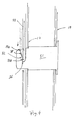
- the front door 22 thus has a suitable locking and sealing, so that the door is locked in the end position of the plug-in unit 20 by actuation of a locking mechanism 30 against the plant housing 1 and a hermetic completion of the opening formed by the plant housing 1 is achieved.
- the plant housing 1 at the front end face several circumferentially pallacee protruding hooks 31, which are each secured in the side member 17.
- the hooks 31 engage through elongated holes 32 of displaceable rails 33 of a rail system 34 in the door 22 or their profiles 35.
- the locking takes place by turning an actuating lever 37, whereby the rails 33 are displaced (see arrows in FIG Fig. 3 and 4 ), to which the rotational movement of the lever 37 is converted via a linkage in a pushing movement of the longitudinal rails 33.
- actuating lever 37 whereby the rails 33 are displaced (see arrows in FIG Fig. 3 and 4 ), to which the rotational movement of the lever 37 is converted via a linkage in a pushing movement of the longitudinal rails 33.
- rotary elements 39 with the cross rails, so that all rails 33 can be moved together.
Landscapes
- Engineering & Computer Science (AREA)
- Power Engineering (AREA)
- Patch Boards (AREA)
Abstract
Claims (15)
- Installation de distribution électrique haute tension ou moyenne tension comportant un boîtier d'installation (1), un élément de commande basse tension (24), un espace de raccordement de câbles (4), un système de barres collectrices (5, 6) et une unité insérable (20) pouvant être insérée et extraite et destinée à des éléments de puissance (23), le boîtier d'installation (1) étant conformé en boîtier extérieur ouvert à l'avant et l'unité insérable (20) étant conformée de telle sorte qu'elle peut être insérée dans le boîtier d'installation (1) et extraite de celle-ci, et l'unité insérable (20) comportant une porte avant (22) intégrée de façon fixe et destinée à fermer hermétiquement l'ouverture ménagée dans le boîtier d'installation (1), caractérisée en ce que l'élément insérable (20) comporte, en plus de l'élément de puissance (23), l'élément de commande basse tension (24).
- Installation de distribution électrique selon la revendication 1, caractérisée en ce que l'élément de commande basse tension (24) est reçu à l'intérieur de l'élément de puissance (23).
- Installation de distribution électrique selon la revendication 2, caractérisé en ce que l'élément basse tension (24) est cloisonné par rapport à l'élément de puissance (23).
- Installation de distribution électrique selon l'une des revendications précédentes, caractérisée en ce que le boîtier installation (1) est fonctionnellement divisé en une partie arrière (2) et une partie avant (3).
- Installation de distribution électrique selon la revendication 4, caractérisée en ce que l'espace de raccordement de câbles (4), le système de barres collectrices (5, 6) et un canal sous pression (7) forment la partie arrière (2) du boîtier d'installation (1).
- Installation de distribution électrique selon la revendication 4 ou 5, caractérisée en ce que la partie avant (3) du boîtier d'installation (1) est conformée pour recevoir l'unité insérable (20).
- Installation de distribution électrique selon l'une des revendications 4 à 6, caractérisée en ce que l'espace de raccordement de câbles (4), le système de barres collectrices (5, 6) et le canal sous pression (7) sont disposés l'un au-dessus de l'autre.
- Installation de distribution électrique selon l'une des revendications 4 à 7, caractérisée en ce que l'espace de raccordement de câbles (4), le système de barres collectrices (5, 6) et le canal sous pression (7) sont cloisonnés l'un par rapport à l'autre dans une direction verticale.
- Installation de distribution électrique selon la revendication 8, caractérisée en ce que la cloison (10, 11, 12) comporte des volets (13, 14, 15) s'ouvrant en direction du canal sous pression (7).
- Installation de distribution électrique selon l'une des revendications précédentes, caractérisée en ce que le système de barres collectrices divisé en deux zones (5, 6) séparées qui sont cloisonnées l'une par rapport à l'autre et qui peuvent être alimentée en courant indépendamment l'une de l'autre.
- Installation de distribution électrique selon l'une des revendications précédentes, caractérisée en ce que l'unité insérable (20) comporte un châssis de type ossature (21) doté d'une porte avant (22) intégrée de façon fixe.
- Installation de distribution électrique selon l'une des revendications précédentes, caractérisée en ce qu'une zone de connexion (18) est disposée dans un longeron latéral avant (17) du boîtier d'installation (1) pour établir une connexion électrique entre l'élément basse tension (24) et les lignes de commande côté client.
- Installation de distribution électrique selon l'une des revendications précédentes, caractérisée en ce que des galets et/ou un agencement de glissière sont prévus pour l'insertion et l'extraction.
- Installation de distribution électrique selon l'une des revendications précédentes, caractérisée en ce que l'unité insérable (20) est conformée de façon à être mobile par un actionnement manuel ou motorisé entre une position de fonctionnement avec alimentation complète, une position de test avec alimentation de l'élément de commande basse tension et une position d'entretien sans aucune alimentation.
- Installation de distribution électrique selon l'une des revendications précédentes, caractérisée en ce qu'il est prévu un mécanisme de verrouillage (3) qui est destiné à fermer hermétiquement l'ouverture, ménagée dans le boîtier d'installation (1), au moyen de la porte avant (22) et qui comporte des éléments mobiles l'un par rapport à l'autre au niveau de la porte avant (22) et du boîtier d'installation (1) dont au moins une partie est dotée de faces obliques perpendiculaires à la direction de déplacement de sorte que, lorsque les éléments se déplacent l'un vers à l'autre pour effectuer le verrouillage, la porte avant (22) est tirée vers le boîtier d'installation (1).
Applications Claiming Priority (2)
| Application Number | Priority Date | Filing Date | Title |
|---|---|---|---|
| DE102009006951A DE102009006951A1 (de) | 2009-01-30 | 2009-01-30 | Mittel-oder Hochspannungsschaltanlage |
| PCT/EP2010/050989 WO2010086364A1 (fr) | 2009-01-30 | 2010-01-28 | Installation de distribution électrique moyenne ou haute tension |
Publications (2)
| Publication Number | Publication Date |
|---|---|
| EP2248236A1 EP2248236A1 (fr) | 2010-11-10 |
| EP2248236B1 true EP2248236B1 (fr) | 2012-07-04 |
Family
ID=42308905
Family Applications (1)
| Application Number | Title | Priority Date | Filing Date |
|---|---|---|---|
| EP10703251A Not-in-force EP2248236B1 (fr) | 2009-01-30 | 2010-01-28 | Installation de distribution électrique moyenne ou haute tension |
Country Status (3)
| Country | Link |
|---|---|
| EP (1) | EP2248236B1 (fr) |
| DE (1) | DE102009006951A1 (fr) |
| WO (1) | WO2010086364A1 (fr) |
Families Citing this family (3)
| Publication number | Priority date | Publication date | Assignee | Title |
|---|---|---|---|---|
| DE102011001731A1 (de) * | 2011-04-01 | 2012-10-04 | Igel Elektronik Gmbh | Vorrichtung zum Sanftanlauf |
| EP3776767B1 (fr) * | 2018-04-05 | 2025-06-04 | ABB Schweiz AG | Module d'appareillages électriques pour installation dans une armoire électrique et armoire électrique comprenant un tel module |
| CN113725767B (zh) * | 2021-08-25 | 2024-08-02 | 惠州市博信电气设备有限公司 | 抽出式开关柜 |
Family Cites Families (10)
| Publication number | Priority date | Publication date | Assignee | Title |
|---|---|---|---|---|
| GB1107033A (en) * | 1964-07-01 | 1968-03-20 | Ass Elect Ind | Improvements in and relating to power switchgear |
| DE1949932C3 (de) | 1969-10-03 | 1974-04-11 | Sachsenwerk Licht- Und Kraft Ag, 6800 Mannheim | Trennerloses Schaltfeld mit ausfahrbarem Schaltwagen |
| DE2515152B2 (de) * | 1975-04-08 | 1980-04-10 | Brown, Boveri & Cie Ag, 6800 Mannheim | Elektrische Schaltanlage für Niederspannung |
| DE3105261C2 (de) | 1981-02-13 | 1987-03-05 | Brown, Boveri & Cie Ag, 6800 Mannheim | Mit einem ein- und ausfahrbaren Schaltwagen ausgestatteter Anlagenschrank für Mittelspannungsschalt- und -verteileranlagen |
| AT383910B (de) * | 1986-01-27 | 1987-09-10 | Sprecher & Schuh Ag | Gekapselte hochspannungs-schaltzelle mit ausfahrbarem trennwagen |
| DE3628113A1 (de) * | 1986-08-19 | 1988-02-25 | Licentia Gmbh | Fabrikfertiger schaltschrank |
| DE3927835A1 (de) | 1989-08-23 | 1991-02-28 | Ritter Starkstromtech | Gekapselte mittelspannungsschaltanlage |
| DE9102514U1 (de) * | 1991-03-02 | 1991-05-23 | ABB Patent GmbH, 6800 Mannheim | Elektrische Mittelspannungsschaltanlage |
| DE4313661C1 (de) * | 1993-01-27 | 1994-04-14 | Siemens Ag | Geräteträger für eine Niederspannungs-Schaltanlage |
| DE9406307U1 (de) | 1994-04-18 | 1994-06-09 | Gustav Hensel Kg, 57368 Lennestadt | Niederspannungs-Schaltanlage |
-
2009
- 2009-01-30 DE DE102009006951A patent/DE102009006951A1/de not_active Withdrawn
-
2010
- 2010-01-28 WO PCT/EP2010/050989 patent/WO2010086364A1/fr not_active Ceased
- 2010-01-28 EP EP10703251A patent/EP2248236B1/fr not_active Not-in-force
Also Published As
| Publication number | Publication date |
|---|---|
| EP2248236A1 (fr) | 2010-11-10 |
| DE102009006951A1 (de) | 2010-08-05 |
| WO2010086364A1 (fr) | 2010-08-05 |
Similar Documents
| Publication | Publication Date | Title |
|---|---|---|
| DE69900069T2 (de) | Anordnung für mehrpolige Schalter | |
| EP2151027B1 (fr) | Installation de distribution haute tension | |
| DE102007045486B4 (de) | Modulare Schaltanlage zur Energieverteilung | |
| DE112018005865T5 (de) | Rangierlokomotive und hochspannung-sicherheitsverriegelungssystem und verfahren davon | |
| DE2525140A1 (de) | Elektrische kontroll- und schaltstation | |
| DE102019212462A1 (de) | Flexible Stromversorgungseinheit | |
| DE3927835A1 (de) | Gekapselte mittelspannungsschaltanlage | |
| EP1442178A1 (fr) | Conteneur mobile | |
| EP2102954B1 (fr) | Module de boîtier enfichable | |
| EP2248236B1 (fr) | Installation de distribution électrique moyenne ou haute tension | |
| EP0624939B1 (fr) | Dispositif de contact pour interrupteurs de puissance rétractables dans des installations de distribution | |
| DE19518126A1 (de) | Leistungsschalter-Anlage | |
| EP3113972B1 (fr) | Véhicule ferroviaire comprenant au moins deux collecteurs de courant | |
| EP3100326A1 (fr) | Dispositif de commutation électrique | |
| DE2949774C3 (de) | Betätigungs- und Verriegelungsvorrichtung für eine Schaltanlage | |
| EP1994538B1 (fr) | Dispositif de sectionnement de courant | |
| DE3437975C2 (de) | Explosionsgeschütztes, elektrisches Betriebsmittel für ortsveränderliche Maschinen des Untertagebetriebes, insbesondere Nachläufer einer Streckenvortriebsmaschine | |
| DE4008419C2 (fr) | ||
| EP0774814B1 (fr) | Elément pour fermer un poste à haute tension | |
| EP2362506B1 (fr) | Dispositif de limitation d'arc électrique | |
| EP0777816B1 (fr) | Train d'alimentation en energie pour exploitations minieres souterraines | |
| DE9000374U1 (de) | Gekapselte, trennerlose Schaltanlage | |
| DE4126786C2 (de) | Elektrische Mittelspannungsschaltanlage | |
| DE202010017261U1 (de) | Elektrische Schaltanlage, insbesondere Mittelspannungsschaltanlage | |
| DE19613151C2 (de) | Elektrisches Schaltfeld |
Legal Events
| Date | Code | Title | Description |
|---|---|---|---|
| PUAI | Public reference made under article 153(3) epc to a published international application that has entered the european phase |
Free format text: ORIGINAL CODE: 0009012 |
|
| 17P | Request for examination filed |
Effective date: 20100916 |
|
| AK | Designated contracting states |
Kind code of ref document: A1 Designated state(s): AT BE BG CH CY CZ DE DK EE ES FI FR GB GR HR HU IE IS IT LI LT LU LV MC MK MT NL NO PL PT RO SE SI SK SM TR |
|
| AX | Request for extension of the european patent |
Extension state: AL BA RS |
|
| GRAP | Despatch of communication of intention to grant a patent |
Free format text: ORIGINAL CODE: EPIDOSNIGR1 |
|
| DAX | Request for extension of the european patent (deleted) | ||
| GRAS | Grant fee paid |
Free format text: ORIGINAL CODE: EPIDOSNIGR3 |
|
| GRAA | (expected) grant |
Free format text: ORIGINAL CODE: 0009210 |
|
| RAP1 | Party data changed (applicant data changed or rights of an application transferred) |
Owner name: IGEL ELECTRIC GMBH |
|
| AK | Designated contracting states |
Kind code of ref document: B1 Designated state(s): AT BE BG CH CY CZ DE DK EE ES FI FR GB GR HR HU IE IS IT LI LT LU LV MC MK MT NL NO PL PT RO SE SI SK SM TR |
|
| REG | Reference to a national code |
Ref country code: GB Ref legal event code: FG4D Free format text: NOT ENGLISH |
|
| REG | Reference to a national code |
Ref country code: CH Ref legal event code: EP |
|
| REG | Reference to a national code |
Ref country code: AT Ref legal event code: REF Ref document number: 565467 Country of ref document: AT Kind code of ref document: T Effective date: 20120715 |
|
| REG | Reference to a national code |
Ref country code: IE Ref legal event code: FG4D Free format text: LANGUAGE OF EP DOCUMENT: GERMAN |
|
| REG | Reference to a national code |
Ref country code: DE Ref legal event code: R082 Ref document number: 502010000991 Country of ref document: DE Representative=s name: MOSER & GOETZE PATENTANWAELTE, DE |
|
| REG | Reference to a national code |
Ref country code: DE Ref legal event code: R096 Ref document number: 502010000991 Country of ref document: DE Effective date: 20120830 |
|
| REG | Reference to a national code |
Ref country code: DE Ref legal event code: R082 Ref document number: 502010000991 Country of ref document: DE Representative=s name: MOSER GOETZE & PARTNER PATENTANWAELTE MBB, DE Effective date: 20120813 Ref country code: DE Ref legal event code: R082 Ref document number: 502010000991 Country of ref document: DE Representative=s name: MOSER & GOETZE PATENTANWAELTE, DE Effective date: 20120813 Ref country code: DE Ref legal event code: R081 Ref document number: 502010000991 Country of ref document: DE Owner name: IGEL ELECTRIC GMBH, DE Free format text: FORMER OWNER: IGEL ELEKTRONIK GMBH, 48324 SENDENHORST, DE Effective date: 20120813 |
|
| REG | Reference to a national code |
Ref country code: NL Ref legal event code: VDEP Effective date: 20120704 |
|
| PG25 | Lapsed in a contracting state [announced via postgrant information from national office to epo] |
Ref country code: SI Free format text: LAPSE BECAUSE OF FAILURE TO SUBMIT A TRANSLATION OF THE DESCRIPTION OR TO PAY THE FEE WITHIN THE PRESCRIBED TIME-LIMIT Effective date: 20120704 |
|
| REG | Reference to a national code |
Ref country code: LT Ref legal event code: MG4D Effective date: 20120704 |
|
| PG25 | Lapsed in a contracting state [announced via postgrant information from national office to epo] |
Ref country code: HR Free format text: LAPSE BECAUSE OF FAILURE TO SUBMIT A TRANSLATION OF THE DESCRIPTION OR TO PAY THE FEE WITHIN THE PRESCRIBED TIME-LIMIT Effective date: 20120704 Ref country code: LT Free format text: LAPSE BECAUSE OF FAILURE TO SUBMIT A TRANSLATION OF THE DESCRIPTION OR TO PAY THE FEE WITHIN THE PRESCRIBED TIME-LIMIT Effective date: 20120704 Ref country code: IS Free format text: LAPSE BECAUSE OF FAILURE TO SUBMIT A TRANSLATION OF THE DESCRIPTION OR TO PAY THE FEE WITHIN THE PRESCRIBED TIME-LIMIT Effective date: 20121104 Ref country code: NO Free format text: LAPSE BECAUSE OF FAILURE TO SUBMIT A TRANSLATION OF THE DESCRIPTION OR TO PAY THE FEE WITHIN THE PRESCRIBED TIME-LIMIT Effective date: 20121004 Ref country code: CY Free format text: LAPSE BECAUSE OF FAILURE TO SUBMIT A TRANSLATION OF THE DESCRIPTION OR TO PAY THE FEE WITHIN THE PRESCRIBED TIME-LIMIT Effective date: 20120704 Ref country code: FI Free format text: LAPSE BECAUSE OF FAILURE TO SUBMIT A TRANSLATION OF THE DESCRIPTION OR TO PAY THE FEE WITHIN THE PRESCRIBED TIME-LIMIT Effective date: 20120704 |
|
| PG25 | Lapsed in a contracting state [announced via postgrant information from national office to epo] |
Ref country code: PT Free format text: LAPSE BECAUSE OF FAILURE TO SUBMIT A TRANSLATION OF THE DESCRIPTION OR TO PAY THE FEE WITHIN THE PRESCRIBED TIME-LIMIT Effective date: 20121105 Ref country code: LV Free format text: LAPSE BECAUSE OF FAILURE TO SUBMIT A TRANSLATION OF THE DESCRIPTION OR TO PAY THE FEE WITHIN THE PRESCRIBED TIME-LIMIT Effective date: 20120704 Ref country code: GR Free format text: LAPSE BECAUSE OF FAILURE TO SUBMIT A TRANSLATION OF THE DESCRIPTION OR TO PAY THE FEE WITHIN THE PRESCRIBED TIME-LIMIT Effective date: 20121005 Ref country code: SE Free format text: LAPSE BECAUSE OF FAILURE TO SUBMIT A TRANSLATION OF THE DESCRIPTION OR TO PAY THE FEE WITHIN THE PRESCRIBED TIME-LIMIT Effective date: 20120704 Ref country code: PL Free format text: LAPSE BECAUSE OF FAILURE TO SUBMIT A TRANSLATION OF THE DESCRIPTION OR TO PAY THE FEE WITHIN THE PRESCRIBED TIME-LIMIT Effective date: 20120704 |
|
| PG25 | Lapsed in a contracting state [announced via postgrant information from national office to epo] |
Ref country code: NL Free format text: LAPSE BECAUSE OF FAILURE TO SUBMIT A TRANSLATION OF THE DESCRIPTION OR TO PAY THE FEE WITHIN THE PRESCRIBED TIME-LIMIT Effective date: 20120704 |
|
| PG25 | Lapsed in a contracting state [announced via postgrant information from national office to epo] |
Ref country code: ES Free format text: LAPSE BECAUSE OF FAILURE TO SUBMIT A TRANSLATION OF THE DESCRIPTION OR TO PAY THE FEE WITHIN THE PRESCRIBED TIME-LIMIT Effective date: 20121015 Ref country code: DK Free format text: LAPSE BECAUSE OF FAILURE TO SUBMIT A TRANSLATION OF THE DESCRIPTION OR TO PAY THE FEE WITHIN THE PRESCRIBED TIME-LIMIT Effective date: 20120704 Ref country code: RO Free format text: LAPSE BECAUSE OF FAILURE TO SUBMIT A TRANSLATION OF THE DESCRIPTION OR TO PAY THE FEE WITHIN THE PRESCRIBED TIME-LIMIT Effective date: 20120704 Ref country code: CZ Free format text: LAPSE BECAUSE OF FAILURE TO SUBMIT A TRANSLATION OF THE DESCRIPTION OR TO PAY THE FEE WITHIN THE PRESCRIBED TIME-LIMIT Effective date: 20120704 Ref country code: EE Free format text: LAPSE BECAUSE OF FAILURE TO SUBMIT A TRANSLATION OF THE DESCRIPTION OR TO PAY THE FEE WITHIN THE PRESCRIBED TIME-LIMIT Effective date: 20120704 |
|
| PLBE | No opposition filed within time limit |
Free format text: ORIGINAL CODE: 0009261 |
|
| STAA | Information on the status of an ep patent application or granted ep patent |
Free format text: STATUS: NO OPPOSITION FILED WITHIN TIME LIMIT |
|
| PG25 | Lapsed in a contracting state [announced via postgrant information from national office to epo] |
Ref country code: SK Free format text: LAPSE BECAUSE OF FAILURE TO SUBMIT A TRANSLATION OF THE DESCRIPTION OR TO PAY THE FEE WITHIN THE PRESCRIBED TIME-LIMIT Effective date: 20120704 |
|
| 26N | No opposition filed |
Effective date: 20130405 |
|
| BERE | Be: lapsed |
Owner name: IGEL ELECTRIC G.M.B.H. Effective date: 20130131 |
|
| PG25 | Lapsed in a contracting state [announced via postgrant information from national office to epo] |
Ref country code: BG Free format text: LAPSE BECAUSE OF FAILURE TO SUBMIT A TRANSLATION OF THE DESCRIPTION OR TO PAY THE FEE WITHIN THE PRESCRIBED TIME-LIMIT Effective date: 20121004 |
|
| REG | Reference to a national code |
Ref country code: DE Ref legal event code: R097 Ref document number: 502010000991 Country of ref document: DE Effective date: 20130405 |
|
| PG25 | Lapsed in a contracting state [announced via postgrant information from national office to epo] |
Ref country code: MC Free format text: LAPSE BECAUSE OF NON-PAYMENT OF DUE FEES Effective date: 20130131 |
|
| REG | Reference to a national code |
Ref country code: IE Ref legal event code: MM4A |
|
| PG25 | Lapsed in a contracting state [announced via postgrant information from national office to epo] |
Ref country code: BE Free format text: LAPSE BECAUSE OF NON-PAYMENT OF DUE FEES Effective date: 20130131 |
|
| PG25 | Lapsed in a contracting state [announced via postgrant information from national office to epo] |
Ref country code: IE Free format text: LAPSE BECAUSE OF NON-PAYMENT OF DUE FEES Effective date: 20130128 |
|
| PGFP | Annual fee paid to national office [announced via postgrant information from national office to epo] |
Ref country code: IT Payment date: 20140122 Year of fee payment: 5 |
|
| PG25 | Lapsed in a contracting state [announced via postgrant information from national office to epo] |
Ref country code: MT Free format text: LAPSE BECAUSE OF FAILURE TO SUBMIT A TRANSLATION OF THE DESCRIPTION OR TO PAY THE FEE WITHIN THE PRESCRIBED TIME-LIMIT Effective date: 20120704 |
|
| REG | Reference to a national code |
Ref country code: CH Ref legal event code: PL |
|
| PG25 | Lapsed in a contracting state [announced via postgrant information from national office to epo] |
Ref country code: LI Free format text: LAPSE BECAUSE OF NON-PAYMENT OF DUE FEES Effective date: 20140131 Ref country code: CH Free format text: LAPSE BECAUSE OF NON-PAYMENT OF DUE FEES Effective date: 20140131 |
|
| PG25 | Lapsed in a contracting state [announced via postgrant information from national office to epo] |
Ref country code: SM Free format text: LAPSE BECAUSE OF FAILURE TO SUBMIT A TRANSLATION OF THE DESCRIPTION OR TO PAY THE FEE WITHIN THE PRESCRIBED TIME-LIMIT Effective date: 20120704 |
|
| PG25 | Lapsed in a contracting state [announced via postgrant information from national office to epo] |
Ref country code: MK Free format text: LAPSE BECAUSE OF FAILURE TO SUBMIT A TRANSLATION OF THE DESCRIPTION OR TO PAY THE FEE WITHIN THE PRESCRIBED TIME-LIMIT Effective date: 20120704 Ref country code: LU Free format text: LAPSE BECAUSE OF NON-PAYMENT OF DUE FEES Effective date: 20130128 Ref country code: HU Free format text: LAPSE BECAUSE OF FAILURE TO SUBMIT A TRANSLATION OF THE DESCRIPTION OR TO PAY THE FEE WITHIN THE PRESCRIBED TIME-LIMIT; INVALID AB INITIO Effective date: 20100128 |
|
| PG25 | Lapsed in a contracting state [announced via postgrant information from national office to epo] |
Ref country code: IT Free format text: LAPSE BECAUSE OF NON-PAYMENT OF DUE FEES Effective date: 20150128 |
|
| REG | Reference to a national code |
Ref country code: FR Ref legal event code: PLFP Year of fee payment: 7 |
|
| REG | Reference to a national code |
Ref country code: AT Ref legal event code: MM01 Ref document number: 565467 Country of ref document: AT Kind code of ref document: T Effective date: 20150128 |
|
| PGFP | Annual fee paid to national office [announced via postgrant information from national office to epo] |
Ref country code: TR Payment date: 20160107 Year of fee payment: 7 |
|
| PG25 | Lapsed in a contracting state [announced via postgrant information from national office to epo] |
Ref country code: AT Free format text: LAPSE BECAUSE OF NON-PAYMENT OF DUE FEES Effective date: 20150128 |
|
| PGFP | Annual fee paid to national office [announced via postgrant information from national office to epo] |
Ref country code: FR Payment date: 20160121 Year of fee payment: 7 Ref country code: GB Payment date: 20160120 Year of fee payment: 7 |
|
| GBPC | Gb: european patent ceased through non-payment of renewal fee |
Effective date: 20170128 |
|
| REG | Reference to a national code |
Ref country code: FR Ref legal event code: ST Effective date: 20170929 |
|
| PG25 | Lapsed in a contracting state [announced via postgrant information from national office to epo] |
Ref country code: FR Free format text: LAPSE BECAUSE OF NON-PAYMENT OF DUE FEES Effective date: 20170131 |
|
| PG25 | Lapsed in a contracting state [announced via postgrant information from national office to epo] |
Ref country code: GB Free format text: LAPSE BECAUSE OF NON-PAYMENT OF DUE FEES Effective date: 20170128 |
|
| PGFP | Annual fee paid to national office [announced via postgrant information from national office to epo] |
Ref country code: DE Payment date: 20180131 Year of fee payment: 9 |
|
| REG | Reference to a national code |
Ref country code: DE Ref legal event code: R119 Ref document number: 502010000991 Country of ref document: DE |
|
| PG25 | Lapsed in a contracting state [announced via postgrant information from national office to epo] |
Ref country code: DE Free format text: LAPSE BECAUSE OF NON-PAYMENT OF DUE FEES Effective date: 20190801 |
|
| PG25 | Lapsed in a contracting state [announced via postgrant information from national office to epo] |
Ref country code: TR Free format text: LAPSE BECAUSE OF NON-PAYMENT OF DUE FEES Effective date: 20170128 |