EP2248410B1 - Chariot de transport pour un tablier de coupe d'une moissonneuse - Google Patents
Chariot de transport pour un tablier de coupe d'une moissonneuse Download PDFInfo
- Publication number
- EP2248410B1 EP2248410B1 EP20100153807 EP10153807A EP2248410B1 EP 2248410 B1 EP2248410 B1 EP 2248410B1 EP 20100153807 EP20100153807 EP 20100153807 EP 10153807 A EP10153807 A EP 10153807A EP 2248410 B1 EP2248410 B1 EP 2248410B1
- Authority
- EP
- European Patent Office
- Prior art keywords
- transport vehicle
- wheel
- axis
- portal
- chassis portion
- Prior art date
- Legal status (The legal status is an assumption and is not a legal conclusion. Google has not performed a legal analysis and makes no representation as to the accuracy of the status listed.)
- Active
Links
Images

Classifications
-
- A—HUMAN NECESSITIES
- A01—AGRICULTURE; FORESTRY; ANIMAL HUSBANDRY; HUNTING; TRAPPING; FISHING
- A01D—HARVESTING; MOWING
- A01D75/00—Accessories for harvesters or mowers
- A01D75/002—Carriers for the transport of harvesters or mowers
-
- B—PERFORMING OPERATIONS; TRANSPORTING
- B62—LAND VEHICLES FOR TRAVELLING OTHERWISE THAN ON RAILS
- B62D—MOTOR VEHICLES; TRAILERS
- B62D13/00—Steering specially adapted for trailers
- B62D13/02—Steering specially adapted for trailers for centrally-pivoted axles
-
- B—PERFORMING OPERATIONS; TRANSPORTING
- B62—LAND VEHICLES FOR TRAVELLING OTHERWISE THAN ON RAILS
- B62D—MOTOR VEHICLES; TRAILERS
- B62D21/00—Understructures, i.e. chassis frame on which a vehicle body may be mounted
- B62D21/02—Understructures, i.e. chassis frame on which a vehicle body may be mounted comprising longitudinally or transversely arranged frame members
- B62D21/04—Understructures, i.e. chassis frame on which a vehicle body may be mounted comprising longitudinally or transversely arranged frame members single longitudinal type
-
- B—PERFORMING OPERATIONS; TRANSPORTING
- B62—LAND VEHICLES FOR TRAVELLING OTHERWISE THAN ON RAILS
- B62D—MOTOR VEHICLES; TRAILERS
- B62D21/00—Understructures, i.e. chassis frame on which a vehicle body may be mounted
- B62D21/14—Understructures, i.e. chassis frame on which a vehicle body may be mounted of adjustable length or width
-
- B—PERFORMING OPERATIONS; TRANSPORTING
- B62—LAND VEHICLES FOR TRAVELLING OTHERWISE THAN ON RAILS
- B62D—MOTOR VEHICLES; TRAILERS
- B62D21/00—Understructures, i.e. chassis frame on which a vehicle body may be mounted
- B62D21/18—Understructures, i.e. chassis frame on which a vehicle body may be mounted characterised by the vehicle type and not provided for in groups B62D21/02 - B62D21/17
- B62D21/20—Understructures, i.e. chassis frame on which a vehicle body may be mounted characterised by the vehicle type and not provided for in groups B62D21/02 - B62D21/17 trailer type, i.e. a frame specifically constructed for use in a non-powered vehicle
Definitions
- the present invention relates to a trolley for a harvester attachment, in particular for a cutting unit of a combine harvester.
- the width of such harvester attachments is regularly substantially greater than the allowable maximum width of a vehicle on public roads so that a mounted harvested harvester can not use public roads.
- a trolley is regularly required, on which the attachment can be transported oriented transversely to its working direction.
- a trolley must be able to compensate for unevenness of the traveled surface, because if, for example, a wheel loses contact with the roadway in a two-axle trolley, the trolley is stable only if its center of gravity is above one of the footprints of the remaining three wheels Triangle is located. Since this requirement is not met for every possible combination of three wheels, there is a risk that a rigid trolley will tip when a wheel loses contact with the ground.
- a trolley for a harvesting machine attachment according to the preamble of claim 1 is known.
- a front axle is connected to a harvesting machine attachment receiving frame via a turntable, and the fifth wheel is to compensate for unevenness in relation to the frame about a extending in the vehicle longitudinal direction of compensation axis pivotable.
- the front axle When driving straight ahead and cornering with moderate steering angle can be maintained by pivoting the front axle about the compensating axle ground contact for all four wheels.
- Object of the present invention is to provide a trolley for a harvester attachment, which is able to ensure a large steering angle of the front chassis part without an abutment of the wheels on the frame.
- the object is achieved by, in a trolley for a harvester attachment with a frame and a front and a rear chassis part, each having at least one wheel axle, wherein the front chassis part is pivotable relative to the frame about a vertical steering axis and a horizontal compensating axis, the Compensating axle pivots together with the at least one wheel axle of the front chassis part about the steering axis. Since, as a result, the compensating axle and wheel axle can never become parallel, there is no danger of the transport truck reacting to a pulling force exerted by a towing vehicle rather than rolling the wheels about the wheel axle by tilting about the compensating axle.
- a portal is formed in a longitudinal member of the frame, in which when cornering a wheel of the front chassis part can intervene.
- Means for at least partially blocking the pivotability of the front chassis part about the compensating axis are expediently designed to be effective in the event of engagement of a wheel in the portal.
- the front chassis part be provided with smaller wheels than the rear chassis part.
- the pivoting of the compensating axle together with the wheel axle can be advantageously ensured by the fact that the compensating axle is fixed by a hinge which connects the at least one wheel axle of the front chassis part to the turntable ,
- the means for blocking the pivoting of the front chassis part restrict its freedom of pivoting movement about the balance axis only on one side, ie of the two opposite stop positions of the pivoting movement about the compensating axis is only that through the means for Block made unattainable, in which this is essential to avoid contact of a wheel with the frame, whereas the other stop position remains accessible and can be taken when the contour of the traveled underground requires it.
- the means for at least partially blocking the pivotability may in particular be designed to deflect the wheel axle from a middle position of the pivoting movement about the compensating axle.
- a wheel engaging under the frame by a steering movement of the fifth wheel can be forced into a lower position than an opposite wheel of the same axle. This reduces the ground clearance of the frame, which is required for a strong steering angle of the front chassis part.
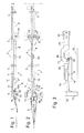
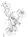
- the Fig. 1 and 2 show a transport vehicle according to the invention for a harvester attachment in a side view and a plan view, respectively.
- a rigid frame of the transport vehicle comprises as main components a side member 1, which, apart from a drawbar 2, extends substantially over the entire length of the vehicle, fixed to the side rail 1, oriented in the vehicle transverse direction arms 3 and support structures on the arms 3, the can be configured specifically for the respective header to be transported.
- the support structures here comprise, among other things, a plurality of longitudinal arms 4 carried by two arms 3 and invisible in the figures, upwardly open hopper or cup, which are provided to receive locking pins of the harvesting machine attachment to be transported and this so in the horizontal direction on the transport vehicle to fix.
- the longitudinal member 1 is composed of a plurality of longitudinal beam pieces 6, 7, 8, 9, which are each connected in pairs by a sleeve 10.
- the rear longitudinal beam pieces 7, 8, 9 each consist essentially of a piece of hollow profile of rectangular cross section
- the front longitudinal beam piece 6 comprises two hollow profile sections 20, 21, which are interconnected by a portal 11.
- a rear wheel axle 12 with wheels 13 is rigidly secured to the longitudinal beam piece 8.
- the drawbar 2 engages a base plate 17 of a turntable, which is connected to the foremost longitudinal beam piece 6 via a turntable 16.
- a front wheel axle 14 is in turn connected to the base plate 17 about a compensating axis 5 (see Fig. 3 ) pivotally suspended, which extends in the longitudinal direction of the drawbar 2 and thus is always oriented at right angles to the wheel axle 14.
- the drawbar 2 is deflected at right angles to the longitudinal member 1, one of the wheels 15 of the front wheel axle 14 is in the downwardly open recess of the portal 11. In order to keep the demands on the ground clearance of the portal 11 low, the front wheels 15 are smaller as the rear wheels 13.
- the portal can 11 be large enough not to touch the wheel 15 engaged therein even when the front wheel axle 14 is pivoted about the compensating axis to a stop position in which the engaging in the portal 11 wheel 15 is higher than the opposite wheel 15 of
- Such a configuration would require an even greater ground clearance of the portal 11, the greater the freedom of pivotal movement of the front axle 14 about the compensating axis 5, and accordingly the center of gravity of the header would come to rest on the transport vehicle.
- this center of gravity should be as low as possible.
- a runner 18 is mounted with two wings projecting obliquely upwards from the side member 1 and to the sides, which approach the right angle when the angle of the front wheel axle 14 approaches , comes into contact with the front wheel axle 14 and limits the free movement of pivoting about the compensating shaft 5 on one side.
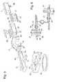
- Fig. 3 shows a schematic side view of the front portion of the transport vehicle with under 90 ° embossed front wheel axle 14.
- the front wheel axle 14 is here provided with two conical rollers 19, one of which when approaching the 90 ° angle of attack with the bottom of the blade 18 in contact device and rolls on this.
- the roller 19 touches the lowest point on the underside of the skid 18 and thus limits the freedom of movement of the wheel axle 14 about the (here perpendicular to the plane of the figure) compensating axle 5 a maximum.
- the wheel axle 14 is horizontally oriented, that is, all four wheels 13, 15 of the vehicle are in contact with the ground when the ground is level, and pivotal movement of the wheel axle 14 in the counterclockwise direction is blocked by contact of the roller 19 with the runner 18. In case of a depression underneath (in the view of Fig. 3 ) left front wheel 15, this would therefore lose ground contact.
- the stability of the vehicle is not significantly affected, since the footprints of the right front wheel 15 and the rear wheels 13 span an isosceles triangle over which the center of gravity of the loaded vehicle is certain.
- the front longitudinal support piece 6 is composed of the portal 11 and the two hollow profile sections 20, 21 which are interconnected by a rear End of the section 20 and a front end of the portion 21 are inserted into receptacles of the portal 11 and welded to the portal 11.
- the two receptacles of the portal 11 each have lateral windows 22 in which the inserted ends of the sections 20, 21 are exposed, and the welded connection between the portal 11 and the sections 20, 21 is produced by welds running along the edges of these windows 22 , The course of these welds is at the sections 20, 21 in Fig. 5 each drawn as a dashed outline 23.
- the rear hollow profile section 21 is welded to a sleeve piece 24 along the edges of a window 25 cut into it.
- the sleeve piece 24 has a hat-shaped cross-section with two vertically projecting from the top and bottom of the hollow profile section 21, extending in the longitudinal direction of the longitudinal member 1 flanges 26.
- a circular cutout 27 is formed in an over the rear end of the hollow profile section 21 projecting portion of the sleeve piece 24 ,
- a second sleeve piece 28, which is similar to the first sleeve piece 24 except for the absence of the cutout 27, and a ring 29 are welded to opposite sides of the longitudinal beam piece 7.
- the longitudinal beam pieces 6, 7 are connected by the flanges 26 of the sleeve pieces 24, 28 are placed opposite to each other, wherein the ring 29 in the cutout 27 is positively engaged, and the sleeve pieces 24, 28 are connected by screwing to complete cuff 10.
- a base plate 30 of substantially octagonal shape is attached to the underside of the hollow profile section 20 and two arms 31 projecting in a cruciform manner from the latter.
- the base plate 30 is stiffened by folded edge webs 32. It serves as a carrier for an upper ring 33 of a turntable.
- the ring 33 is positioned on the base plate 30 by means of four adjustable wedges 34, one of which is in Fig. 6 shown in section.
- the wedge 34 passes through an opening 35 of the base plate 30, and its tip engages in a in plan view C-shaped spacer 36 at the top of the base plate 30 a.
- the wedge 34 is fixed by a clamping screw 37, which acts on the upper side of the spacer 36 and on the underside of the wedge 34.
- An inclined flank 38 of the wedge 34 bears against a complementary beveled flank of a reinforcing block 39 welded to an edge of the opening 35.
- An opposite vertical edge 40 of the wedge 34 presses against the inner circumference of the ring 33.
- the position of the ring 33 on the base plate 30 and thus the position of the fixed by the turntable 16 steering axis of the vehicle regardless of possible manufacturing tolerances of the ring 33 can be set exactly.
- screws 50 which are received in screw holes of the ring 33 and the base plate 30. The screws engage with play into the screw holes. You can therefore record strong vertical tensile forces, but only limited shear forces parallel to the base plate 30. These shear forces are absorbed without play by the voltage applied to the edge of the ring 33 wedges 34.
- a lower ring 41 of the turntable is fixed in an analogous manner by means of pressing against its outer periphery wedges 42 and screws 50 on the base plate 17 of the fifth wheel.
- the base plate 17 with two wedges 42 receiving openings 43 is in Fig. 7 shown in a perspective view.
- the openings 43 are each fixed to the base plate 17 welded, an immovable stop for the ring 41 forming blocks 49.
- the two blocks 49 define the position of the ring 41 on the base plate 17 clearly; the wedges 42 are used here only to compensate for manufacturing tolerances of the ring 41 and to make the ring on the plate 17 in the horizontal direction without play.
- the base plate 17 is stiffened by an outer peripheral edge web 44 and by webs 45 which extend along the edges of a central opening 46.
- Two at the front and rear edge of the opening 46 opposite vertical plates 47 each have a bore 48 which is provided to receive a journal of the front wheel axle 14, which determines the compensation axis 5.
- Fig. 8 shows a side view of the front portion of a trolley according to a modified In this position, none of the front wheels 13 engages in the portal 11, but it can be seen that the diameter of the front wheels 3 is greater here than The maximum ground clearance of the portal 11.
- the wheel axle 14 carries at its top two rollers 19.
- the roller 19 of the right front wheel 13 is in the configuration of Fig. 8 hidden behind the longitudinal beam piece 6 and is higher than the lowest point of the blade 18th
Landscapes
- Engineering & Computer Science (AREA)
- Chemical & Material Sciences (AREA)
- Combustion & Propulsion (AREA)
- Transportation (AREA)
- Mechanical Engineering (AREA)
- Life Sciences & Earth Sciences (AREA)
- Environmental Sciences (AREA)
- Handcart (AREA)
- Agricultural Machines (AREA)
Claims (7)
- Chariot de transport pour un tablier de coupe d'une moissonneuse avec un cadre (1, 3, 4) et une partie de mécanisme de roulement avant et arrière présentant respectivement au moins un essieu de roue (14 ; 12), la partie de mécanisme de roulement avant pouvant pivoter par rapport au cadre autour d'un essieu directeur vertical et d'un axe de compensation (5) horizontal, l'axe de compensation (5) pivotant autour de l'essieu directeur conjointement avec l'au moins un essieu de roue (14) de la partie de mécanisme de roulement avant, caractérisé en ce qu'un portique (11) est formé dans un longeron (1) du cadre et en ce que des moyens (18, 19) sont prévus pour le blocage au moins partiel, en particulier au moins unilatéral de la pivotabilité de la partie de mécanisme de roulement avant autour de l'axe de compensation (5) en cas d'engagement d'une roue (15) dans le portique (11).
- Chariot de transport selon la revendication 1, caractérisé en ce que la partie de mécanisme de roulement avant présente de plus petites roues (15) que la partie de mécanisme de roulement arrière.
- Chariot de transport selon la revendication 1 ou 2, caractérisé en ce que l'essieu directeur est fixé par une couronne de pivotement (16.).
- Chariot de transport selon la revendication 3, caractérisé en ce que l'axe de compensation (5) est fixé par une articulation qui relie l'au moins un essieu de roue (14) de la partie de mécanisme de roulement avant à la couronne de pivotement (16).
- Chariot de transport selon l'une quelconque des revendications précédentes, caractérisé en ce que les moyens (18, 19) sont configurés pour le blocage au moins partiel de la pivotabilité afin de dévier l'essieu de roue (14) d'une position médiane du mouvement de pivotement autour de l'axe de compensation (5).
- Chariot de transport selon l'une quelconque des revendications précédentes, caractérisé en ce que les moyens (18, 19) comportent pour le blocage au moins partiel de la pivotabilité un patin (18) et un rouleau (19) reposant sur le patin (18) en cas d'engagement d'une roue (15) dans le portique (11).
- Chariot de transport selon la revendication 6, caractérisé en ce que le patin (18) est monté sur le cadre (1, 3, 4) et le rouleau (19) sur la partie de mécanisme de roulement avant.
Applications Claiming Priority (1)
| Application Number | Priority Date | Filing Date | Title |
|---|---|---|---|
| DE102009020460A DE102009020460A1 (de) | 2009-05-08 | 2009-05-08 | Transportwagen für einen Erntemaschinenvorsatz |
Publications (3)
| Publication Number | Publication Date |
|---|---|
| EP2248410A2 EP2248410A2 (fr) | 2010-11-10 |
| EP2248410A3 EP2248410A3 (fr) | 2011-05-18 |
| EP2248410B1 true EP2248410B1 (fr) | 2013-01-09 |
Family
ID=42455347
Family Applications (1)
| Application Number | Title | Priority Date | Filing Date |
|---|---|---|---|
| EP20100153807 Active EP2248410B1 (fr) | 2009-05-08 | 2010-02-17 | Chariot de transport pour un tablier de coupe d'une moissonneuse |
Country Status (2)
| Country | Link |
|---|---|
| EP (1) | EP2248410B1 (fr) |
| DE (1) | DE102009020460A1 (fr) |
Families Citing this family (2)
| Publication number | Priority date | Publication date | Assignee | Title |
|---|---|---|---|---|
| DE102011001861B4 (de) * | 2011-04-07 | 2024-12-05 | Dr. Ing. H.C. F. Porsche Ag | Tragstruktur für ein Kraftfahrzeug und Kraftfahrzeug |
| FR3008276B1 (fr) * | 2013-07-11 | 2016-01-22 | Cochet | Chariot de transport d'outillage de coupe pour moissonneuse |
Family Cites Families (7)
| Publication number | Priority date | Publication date | Assignee | Title |
|---|---|---|---|---|
| DE123199C (fr) * | ||||
| GB481622A (en) * | 1936-11-04 | 1938-03-15 | Arthur Marenbon | Improvements in or relating to vehicle trailers |
| BE468262A (fr) * | 1945-10-03 | |||
| US3718343A (en) * | 1971-04-14 | 1973-02-27 | Hamby Co | Ammonia trailer improvements |
| DD114565A1 (fr) | 1974-09-19 | 1975-08-12 | ||
| US4114917A (en) * | 1978-01-16 | 1978-09-19 | Jones Thomas C | Tank trailer |
| FR2899766B1 (fr) * | 2006-04-18 | 2008-06-27 | Perard Sarl | Chariot de transport de barre de coupe et de prolonge de moissonneuse batteuse ou similaire |
-
2009
- 2009-05-08 DE DE102009020460A patent/DE102009020460A1/de not_active Withdrawn
-
2010
- 2010-02-17 EP EP20100153807 patent/EP2248410B1/fr active Active
Also Published As
| Publication number | Publication date |
|---|---|
| EP2248410A2 (fr) | 2010-11-10 |
| EP2248410A3 (fr) | 2011-05-18 |
| DE102009020460A1 (de) | 2010-11-11 |
Similar Documents
| Publication | Publication Date | Title |
|---|---|---|
| EP0808747A1 (fr) | Système de hayon élévateur | |
| EP3083371B1 (fr) | Configuration de suspension pour un véhicule | |
| DE2018218A1 (de) | Anbaugerät für mit einem Hydrauliksystem versehene Fahrzeuge, insbesondere Hublader, zum Verrollen von Containern | |
| EP3007958B1 (fr) | Support d'essieu d'un véhicule comportant un élément de renforcement en matériau composite renforcé par des fibres | |
| DE102009004525B4 (de) | Fangvorrichtung für einen Rollstuhl in einem Fahrzeug, insbesondere Schienenfahrzeug | |
| EP3105109A1 (fr) | Poids lourd modulaire ajustable en largeur et module de châssis transversal pour un poids lourd de ce type | |
| EP2173600B1 (fr) | Châssis auxiliaire proche du train de roulement d'un véhicule à deux lignes | |
| DE69211143T2 (de) | Konstruktion einer achse für lastfahrzeug | |
| DE2746828A1 (de) | Gleiskettenschuh | |
| EP0678443B1 (fr) | Train de roulement, notamment pour machines de travail mobiles et véhicules | |
| EP2248410A2 (fr) | Chariot de transport pour un tablier de coupe d'une moissonneuse | |
| EP1777085B1 (fr) | Suspension d'essieu pour bras tirés portant un essieu | |
| EP1574366B1 (fr) | Suspension d'essieu et plaque de ressort pour la fixation de l'essieu | |
| EP2886424A1 (fr) | Module frontal de châssis en forme d'arc pour remorques de véhicules | |
| EP1854696A1 (fr) | Intercommunication avec une passerelle d'intercirculation entre véhicules articulés | |
| EP2251297B1 (fr) | Chariot de manutention doté d'au moins deux éléments d'habillage | |
| EP3105108A1 (fr) | Poids lourd à largeur réglable | |
| EP2754604B1 (fr) | Plateau pivotant de sellette | |
| EP0530742A2 (fr) | Chariot de manutention à fourches pour palettes | |
| DE2938554C2 (fr) | ||
| DE3741277A1 (de) | Kupplungseinrichtung | |
| AT525811B1 (de) | Vorrichtung zum Festlegen eines Straßendienstgeräts an einem Fahrzeug | |
| DE976824C (de) | Bodenaufbau fuer einen Fahrzeugwagenkasten fuer vereinigte Fahrzeugwagenkasten- und Fahrgestellkonstruktionen | |
| EP0538893B1 (fr) | Sellette d'attelage pour véhicule semi-remorque | |
| DE4224220A1 (de) | Schneepflug |
Legal Events
| Date | Code | Title | Description |
|---|---|---|---|
| PUAI | Public reference made under article 153(3) epc to a published international application that has entered the european phase |
Free format text: ORIGINAL CODE: 0009012 |
|
| AK | Designated contracting states |
Kind code of ref document: A2 Designated state(s): AT BE BG CH CY CZ DE DK EE ES FI FR GB GR HR HU IE IS IT LI LT LU LV MC MK MT NL NO PL PT RO SE SI SK SM TR |
|
| AX | Request for extension of the european patent |
Extension state: AL BA RS |
|
| PUAL | Search report despatched |
Free format text: ORIGINAL CODE: 0009013 |
|
| AK | Designated contracting states |
Kind code of ref document: A3 Designated state(s): AT BE BG CH CY CZ DE DK EE ES FI FR GB GR HR HU IE IS IT LI LT LU LV MC MK MT NL NO PL PT RO SE SI SK SM TR |
|
| AX | Request for extension of the european patent |
Extension state: AL BA RS |
|
| 17P | Request for examination filed |
Effective date: 20111118 |
|
| REG | Reference to a national code |
Ref country code: DE Ref legal event code: R079 Ref document number: 502010002045 Country of ref document: DE Free format text: PREVIOUS MAIN CLASS: A01D0075000000 Ipc: B62D0013020000 |
|
| GRAP | Despatch of communication of intention to grant a patent |
Free format text: ORIGINAL CODE: EPIDOSNIGR1 |
|
| RIC1 | Information provided on ipc code assigned before grant |
Ipc: B62D 21/04 20060101ALI20120828BHEP Ipc: B62D 13/02 20060101AFI20120828BHEP Ipc: B62D 21/14 20060101ALI20120828BHEP Ipc: A01D 75/00 20060101ALN20120828BHEP Ipc: B62D 21/20 20060101ALI20120828BHEP |
|
| GRAS | Grant fee paid |
Free format text: ORIGINAL CODE: EPIDOSNIGR3 |
|
| GRAA | (expected) grant |
Free format text: ORIGINAL CODE: 0009210 |
|
| AK | Designated contracting states |
Kind code of ref document: B1 Designated state(s): AT BE BG CH CY CZ DE DK EE ES FI FR GB GR HR HU IE IS IT LI LT LU LV MC MK MT NL NO PL PT RO SE SI SK SM TR |
|
| REG | Reference to a national code |
Ref country code: GB Ref legal event code: FG4D Free format text: NOT ENGLISH |
|
| REG | Reference to a national code |
Ref country code: CH Ref legal event code: EP Ref country code: AT Ref legal event code: REF Ref document number: 592555 Country of ref document: AT Kind code of ref document: T Effective date: 20130115 |
|
| REG | Reference to a national code |
Ref country code: IE Ref legal event code: FG4D Free format text: LANGUAGE OF EP DOCUMENT: GERMAN |
|
| REG | Reference to a national code |
Ref country code: DE Ref legal event code: R096 Ref document number: 502010002045 Country of ref document: DE Effective date: 20130228 |
|
| PG25 | Lapsed in a contracting state [announced via postgrant information from national office to epo] |
Ref country code: SI Free format text: LAPSE BECAUSE OF FAILURE TO SUBMIT A TRANSLATION OF THE DESCRIPTION OR TO PAY THE FEE WITHIN THE PRESCRIBED TIME-LIMIT Effective date: 20130109 |
|
| REG | Reference to a national code |
Ref country code: NL Ref legal event code: VDEP Effective date: 20130109 |
|
| REG | Reference to a national code |
Ref country code: LT Ref legal event code: MG4D |
|
| PG25 | Lapsed in a contracting state [announced via postgrant information from national office to epo] |
Ref country code: ES Free format text: LAPSE BECAUSE OF FAILURE TO SUBMIT A TRANSLATION OF THE DESCRIPTION OR TO PAY THE FEE WITHIN THE PRESCRIBED TIME-LIMIT Effective date: 20130420 Ref country code: BG Free format text: LAPSE BECAUSE OF FAILURE TO SUBMIT A TRANSLATION OF THE DESCRIPTION OR TO PAY THE FEE WITHIN THE PRESCRIBED TIME-LIMIT Effective date: 20130409 Ref country code: LT Free format text: LAPSE BECAUSE OF FAILURE TO SUBMIT A TRANSLATION OF THE DESCRIPTION OR TO PAY THE FEE WITHIN THE PRESCRIBED TIME-LIMIT Effective date: 20130109 Ref country code: SE Free format text: LAPSE BECAUSE OF FAILURE TO SUBMIT A TRANSLATION OF THE DESCRIPTION OR TO PAY THE FEE WITHIN THE PRESCRIBED TIME-LIMIT Effective date: 20130109 Ref country code: IS Free format text: LAPSE BECAUSE OF FAILURE TO SUBMIT A TRANSLATION OF THE DESCRIPTION OR TO PAY THE FEE WITHIN THE PRESCRIBED TIME-LIMIT Effective date: 20130509 Ref country code: NO Free format text: LAPSE BECAUSE OF FAILURE TO SUBMIT A TRANSLATION OF THE DESCRIPTION OR TO PAY THE FEE WITHIN THE PRESCRIBED TIME-LIMIT Effective date: 20130409 |
|
| PG25 | Lapsed in a contracting state [announced via postgrant information from national office to epo] |
Ref country code: LV Free format text: LAPSE BECAUSE OF FAILURE TO SUBMIT A TRANSLATION OF THE DESCRIPTION OR TO PAY THE FEE WITHIN THE PRESCRIBED TIME-LIMIT Effective date: 20130109 Ref country code: NL Free format text: LAPSE BECAUSE OF FAILURE TO SUBMIT A TRANSLATION OF THE DESCRIPTION OR TO PAY THE FEE WITHIN THE PRESCRIBED TIME-LIMIT Effective date: 20130109 Ref country code: FI Free format text: LAPSE BECAUSE OF FAILURE TO SUBMIT A TRANSLATION OF THE DESCRIPTION OR TO PAY THE FEE WITHIN THE PRESCRIBED TIME-LIMIT Effective date: 20130109 Ref country code: PT Free format text: LAPSE BECAUSE OF FAILURE TO SUBMIT A TRANSLATION OF THE DESCRIPTION OR TO PAY THE FEE WITHIN THE PRESCRIBED TIME-LIMIT Effective date: 20130509 Ref country code: GR Free format text: LAPSE BECAUSE OF FAILURE TO SUBMIT A TRANSLATION OF THE DESCRIPTION OR TO PAY THE FEE WITHIN THE PRESCRIBED TIME-LIMIT Effective date: 20130410 Ref country code: PL Free format text: LAPSE BECAUSE OF FAILURE TO SUBMIT A TRANSLATION OF THE DESCRIPTION OR TO PAY THE FEE WITHIN THE PRESCRIBED TIME-LIMIT Effective date: 20130109 |
|
| PG25 | Lapsed in a contracting state [announced via postgrant information from national office to epo] |
Ref country code: MC Free format text: LAPSE BECAUSE OF NON-PAYMENT OF DUE FEES Effective date: 20130228 Ref country code: HR Free format text: LAPSE BECAUSE OF FAILURE TO SUBMIT A TRANSLATION OF THE DESCRIPTION OR TO PAY THE FEE WITHIN THE PRESCRIBED TIME-LIMIT Effective date: 20130109 |
|
| PG25 | Lapsed in a contracting state [announced via postgrant information from national office to epo] |
Ref country code: SK Free format text: LAPSE BECAUSE OF FAILURE TO SUBMIT A TRANSLATION OF THE DESCRIPTION OR TO PAY THE FEE WITHIN THE PRESCRIBED TIME-LIMIT Effective date: 20130109 Ref country code: CZ Free format text: LAPSE BECAUSE OF FAILURE TO SUBMIT A TRANSLATION OF THE DESCRIPTION OR TO PAY THE FEE WITHIN THE PRESCRIBED TIME-LIMIT Effective date: 20130109 Ref country code: EE Free format text: LAPSE BECAUSE OF FAILURE TO SUBMIT A TRANSLATION OF THE DESCRIPTION OR TO PAY THE FEE WITHIN THE PRESCRIBED TIME-LIMIT Effective date: 20130109 Ref country code: RO Free format text: LAPSE BECAUSE OF FAILURE TO SUBMIT A TRANSLATION OF THE DESCRIPTION OR TO PAY THE FEE WITHIN THE PRESCRIBED TIME-LIMIT Effective date: 20130109 Ref country code: DK Free format text: LAPSE BECAUSE OF FAILURE TO SUBMIT A TRANSLATION OF THE DESCRIPTION OR TO PAY THE FEE WITHIN THE PRESCRIBED TIME-LIMIT Effective date: 20130109 |
|
| PLBE | No opposition filed within time limit |
Free format text: ORIGINAL CODE: 0009261 |
|
| STAA | Information on the status of an ep patent application or granted ep patent |
Free format text: STATUS: NO OPPOSITION FILED WITHIN TIME LIMIT |
|
| REG | Reference to a national code |
Ref country code: FR Ref legal event code: ST Effective date: 20131031 |
|
| REG | Reference to a national code |
Ref country code: HU Ref legal event code: AG4A Ref document number: E017524 Country of ref document: HU |
|
| PG25 | Lapsed in a contracting state [announced via postgrant information from national office to epo] |
Ref country code: CY Free format text: LAPSE BECAUSE OF FAILURE TO SUBMIT A TRANSLATION OF THE DESCRIPTION OR TO PAY THE FEE WITHIN THE PRESCRIBED TIME-LIMIT Effective date: 20130109 |
|
| REG | Reference to a national code |
Ref country code: IE Ref legal event code: MM4A |
|
| 26N | No opposition filed |
Effective date: 20131010 |
|
| PG25 | Lapsed in a contracting state [announced via postgrant information from national office to epo] |
Ref country code: IT Free format text: LAPSE BECAUSE OF FAILURE TO SUBMIT A TRANSLATION OF THE DESCRIPTION OR TO PAY THE FEE WITHIN THE PRESCRIBED TIME-LIMIT Effective date: 20130109 |
|
| REG | Reference to a national code |
Ref country code: DE Ref legal event code: R097 Ref document number: 502010002045 Country of ref document: DE Effective date: 20131010 |
|
| PG25 | Lapsed in a contracting state [announced via postgrant information from national office to epo] |
Ref country code: FR Free format text: LAPSE BECAUSE OF NON-PAYMENT OF DUE FEES Effective date: 20130311 Ref country code: IE Free format text: LAPSE BECAUSE OF NON-PAYMENT OF DUE FEES Effective date: 20130217 |
|
| PG25 | Lapsed in a contracting state [announced via postgrant information from national office to epo] |
Ref country code: MT Free format text: LAPSE BECAUSE OF FAILURE TO SUBMIT A TRANSLATION OF THE DESCRIPTION OR TO PAY THE FEE WITHIN THE PRESCRIBED TIME-LIMIT Effective date: 20130109 |
|
| REG | Reference to a national code |
Ref country code: CH Ref legal event code: PL |
|
| GBPC | Gb: european patent ceased through non-payment of renewal fee |
Effective date: 20140217 |
|
| PG25 | Lapsed in a contracting state [announced via postgrant information from national office to epo] |
Ref country code: LI Free format text: LAPSE BECAUSE OF NON-PAYMENT OF DUE FEES Effective date: 20140228 Ref country code: CH Free format text: LAPSE BECAUSE OF NON-PAYMENT OF DUE FEES Effective date: 20140228 |
|
| PG25 | Lapsed in a contracting state [announced via postgrant information from national office to epo] |
Ref country code: GB Free format text: LAPSE BECAUSE OF NON-PAYMENT OF DUE FEES Effective date: 20140217 |
|
| PG25 | Lapsed in a contracting state [announced via postgrant information from national office to epo] |
Ref country code: SM Free format text: LAPSE BECAUSE OF FAILURE TO SUBMIT A TRANSLATION OF THE DESCRIPTION OR TO PAY THE FEE WITHIN THE PRESCRIBED TIME-LIMIT Effective date: 20130109 |
|
| PG25 | Lapsed in a contracting state [announced via postgrant information from national office to epo] |
Ref country code: TR Free format text: LAPSE BECAUSE OF FAILURE TO SUBMIT A TRANSLATION OF THE DESCRIPTION OR TO PAY THE FEE WITHIN THE PRESCRIBED TIME-LIMIT Effective date: 20130109 |
|
| PG25 | Lapsed in a contracting state [announced via postgrant information from national office to epo] |
Ref country code: LU Free format text: LAPSE BECAUSE OF NON-PAYMENT OF DUE FEES Effective date: 20130217 Ref country code: MK Free format text: LAPSE BECAUSE OF FAILURE TO SUBMIT A TRANSLATION OF THE DESCRIPTION OR TO PAY THE FEE WITHIN THE PRESCRIBED TIME-LIMIT Effective date: 20130109 |
|
| P01 | Opt-out of the competence of the unified patent court (upc) registered |
Effective date: 20230515 |
|
| REG | Reference to a national code |
Ref country code: DE Ref legal event code: R084 Ref document number: 502010002045 Country of ref document: DE |
|
| PGFP | Annual fee paid to national office [announced via postgrant information from national office to epo] |
Ref country code: HU Payment date: 20260220 Year of fee payment: 17 |
|
| PGFP | Annual fee paid to national office [announced via postgrant information from national office to epo] |
Ref country code: DE Payment date: 20260218 Year of fee payment: 17 |
|
| PGFP | Annual fee paid to national office [announced via postgrant information from national office to epo] |
Ref country code: AT Payment date: 20260219 Year of fee payment: 17 |
|
| PGFP | Annual fee paid to national office [announced via postgrant information from national office to epo] |
Ref country code: BE Payment date: 20260218 Year of fee payment: 17 |