EP2248460A1 - Microscope stéréoscopique - Google Patents
Microscope stéréoscopique Download PDFInfo
- Publication number
- EP2248460A1 EP2248460A1 EP09716258A EP09716258A EP2248460A1 EP 2248460 A1 EP2248460 A1 EP 2248460A1 EP 09716258 A EP09716258 A EP 09716258A EP 09716258 A EP09716258 A EP 09716258A EP 2248460 A1 EP2248460 A1 EP 2248460A1
- Authority
- EP
- European Patent Office
- Prior art keywords
- optical axis
- lens
- observation
- head lens
- head
- Prior art date
- Legal status (The legal status is an assumption and is not a legal conclusion. Google has not performed a legal analysis and makes no representation as to the accuracy of the status listed.)
- Withdrawn
Links
Images






Classifications
-
- A—HUMAN NECESSITIES
- A61—MEDICAL OR VETERINARY SCIENCE; HYGIENE
- A61B—DIAGNOSIS; SURGERY; IDENTIFICATION
- A61B3/00—Apparatus for testing the eyes; Instruments for examining the eyes
- A61B3/10—Objective types, i.e. instruments for examining the eyes independent of the patients' perceptions or reactions
- A61B3/14—Arrangements specially adapted for eye photography
- A61B3/15—Arrangements specially adapted for eye photography with means for aligning, spacing or blocking spurious reflection ; with means for relaxing
- A61B3/156—Arrangements specially adapted for eye photography with means for aligning, spacing or blocking spurious reflection ; with means for relaxing for blocking
-
- A—HUMAN NECESSITIES
- A61—MEDICAL OR VETERINARY SCIENCE; HYGIENE
- A61B—DIAGNOSIS; SURGERY; IDENTIFICATION
- A61B3/00—Apparatus for testing the eyes; Instruments for examining the eyes
- A61B3/10—Objective types, i.e. instruments for examining the eyes independent of the patients' perceptions or reactions
- A61B3/13—Ophthalmic microscopes
- A61B3/132—Ophthalmic microscopes in binocular arrangement
-
- A—HUMAN NECESSITIES
- A61—MEDICAL OR VETERINARY SCIENCE; HYGIENE
- A61B—DIAGNOSIS; SURGERY; IDENTIFICATION
- A61B3/00—Apparatus for testing the eyes; Instruments for examining the eyes
- A61B3/10—Objective types, i.e. instruments for examining the eyes independent of the patients' perceptions or reactions
- A61B3/13—Ophthalmic microscopes
- A61B3/135—Slit-lamp microscopes
-
- G—PHYSICS
- G02—OPTICS
- G02B—OPTICAL ELEMENTS, SYSTEMS OR APPARATUS
- G02B21/00—Microscopes
- G02B21/06—Means for illuminating specimens
-
- G—PHYSICS
- G02—OPTICS
- G02B—OPTICAL ELEMENTS, SYSTEMS OR APPARATUS
- G02B21/00—Microscopes
- G02B21/18—Arrangements with more than one light path, e.g. for comparing two specimens
- G02B21/20—Binocular arrangements
- G02B21/22—Stereoscopic arrangements
-
- A—HUMAN NECESSITIES
- A61—MEDICAL OR VETERINARY SCIENCE; HYGIENE
- A61B—DIAGNOSIS; SURGERY; IDENTIFICATION
- A61B90/00—Instruments, implements or accessories specially adapted for surgery or diagnosis and not covered by any of the groups A61B1/00 - A61B50/00, e.g. for luxation treatment or for protecting wound edges
- A61B90/20—Surgical microscopes characterised by non-optical aspects
-
- A—HUMAN NECESSITIES
- A61—MEDICAL OR VETERINARY SCIENCE; HYGIENE
- A61F—FILTERS IMPLANTABLE INTO BLOOD VESSELS; PROSTHESES; DEVICES PROVIDING PATENCY TO, OR PREVENTING COLLAPSING OF, TUBULAR STRUCTURES OF THE BODY, e.g. STENTS; ORTHOPAEDIC, NURSING OR CONTRACEPTIVE DEVICES; FOMENTATION; TREATMENT OR PROTECTION OF EYES OR EARS; BANDAGES, DRESSINGS OR ABSORBENT PADS; FIRST-AID KITS
- A61F9/00—Methods or devices for treatment of the eyes; Devices for putting in contact-lenses; Devices to correct squinting; Apparatus to guide the blind; Protective devices for the eyes, carried on the body or in the hand
- A61F9/007—Methods or devices for eye surgery
Definitions
- the present invention relates to a stereomicroscope used in the ophthalmologic field, more specifically, a technique for intraocular observation.
- an ophthalmologic stereomicroscope In the ophthalmologic field, various kinds of stereomicroscopes such as a slit lamp microscope and a surgical microscope are used.
- An ophthalmologic stereomicroscope is generally configured to enable binocular observation of an eye.
- such a stereomicroscope is configured to enable observation of not only an anterior segment (the cornea and so on) but also the inside of an eye.
- the "inside of an eye” refers to a site within the pupil, for example, the fundus oculi (the retina) and the vitreous body.
- a specific lens is placed between an objective lens and an eye.
- a head lens placed in non-contact with an eye is used.
- the head lens is held by a lens holder in Patent Document 1, the head lens may be grasped by the operator and used.
- Patent Document 2 A surgical microscope described in Patent Document 2 is configured to enable intraocular observation in a state that a head lens is placed in non-contact with an eye.
- Patent Document 3 discloses a contact lens placed in contact with an eye during surgery.
- a lens placed between an objective lens and an eye for intraocular observation as described above will be generically referred to as a head lens.
- an observation field has been set narrow in order to decrease or eliminate flare caused by the head lens. Therefore, only a narrow range of the fundus oculi has been observed at one time with the conventional stereomicroscope.
- a slit light has been used as an illumination light, and it has been possible to obtain only a narrow slit-like illumination field.
- setting an observation field has been performed depending on the technique of the operator, it has not been easy to set a favorable observation field.
- the present invention has been made in order to solve the aforementioned problems, and an object of the present invention is to provide a stereomicroscope configured to enable intraocular observation with a wide observation field while preventing occurrence of flare.
- a stereomicroscope comprises: an illumination system including a light source configured to output an illumination light and an illumination diaphragm configured to interrupt part of the illumination light, the illumination system being configured to project the illumination light propagated through the illumination diaphragm to an eye; an observation system having an objective lens, and right and left optical systems each configured to guide a light reflected by the eye of the illumination light propagated through the objective lens; a first mechanism configured to move the illumination system in a lateral direction; and a head lens placed between the objective lens and the eye, wherein at the time of intraocular observation of the eye, in a state that an optical axis of the illumination system and an optical axis of the observation system are arranged so as to be nonparallel by the first mechanism and an optical axis of the head lens and an optical axis of the objective lens are arranged so as to be separate in the lateral direction, the illumination light emitted from the illumination system is caused to enter the eye via the
- the stereomicroscope according to the first aspect further comprises a second mechanism configured to support the head lens and move the head lens at least in the lateral direction.
- the stereomicroscope at the time of intraocular observation of the eye, the optical axis of the head lens and the optical axis of the objective lens are arranged so as to be separate in the lateral direction by the second mechanism.
- the intraocularly reflected light is caused to enter the optical system on the one side of the right and left optical systems.
- the observation system includes an interrupting part configured to interrupt the light having entered the optical system on the other side of the right and left optical systems.
- the observation system includes a projector configured to project a fixation target to the eye via the optical system on the one side.
- the first mechanism includes a rotation mechanism configured to support the illumination system so as to be rotatable around an axis orthogonal to the optical axis of the illumination system.
- the first mechanism includes a first actuator configured to generate a driving force, the first mechanism being configured to move the illumination system by the generated driving force.
- the stereomicroscope according to the seventh aspect further comprises: a manipulation part; and a controller configured to, in response to manipulation of the manipulation part, control the first actuator to move the illumination system so that the optical axis of the illumination system and the optical axis of the observation system form a predetermined angle.
- the second mechanism is configured to move the head lens in an anteroposterior direction and/or a vertical direction.
- the second mechanism includes a manipulation part used for moving the head lens.
- the second mechanism includes a second actuator configured to generate a driving force, the second mechanism being configured to move the head lens by the generated driving force.
- the stereomicroscope according to the eleventh aspect further comprises: a manipulation part; and a controller configured to, in response to manipulation of the manipulation part, control the second actuator to move the head lens so that the optical axis of the head lens and the optical axis of the objective lens are separated at a predetermined distance.
- the illumination system further includes a slitting part configured to form a slit for generating a slit light based on the illumination light outputted from the light source, the illumination system being configured to project the slit light to the eye;
- the first mechanism includes a first actuator configured to generate a driving force, the first mechanism being configured to move the illumination system by the generated driving force;
- the second mechanism includes a second actuator configured to generate a driving force, the second mechanism being configured to move the head lens by the generated driving force.
- the stereomicroscope further comprises: a manipulation part configured to switch from an anterior segment observation mode using the slit light to an intraocular observation mode; and a controller configured to, in response to manipulation of the manipulation part, control the slitting part to end formation of the slit, control the illumination diaphragm to set to a predetermined aperture value, control the first actuator to move the illumination system so that the optical axis of the illumination system and the optical axis of the observation system form a predetermined angle, and control the second actuator to move the head lens so that the optical axis of the head lens and the optical axis of the objective lens are separated at a predetermined distance.
- the illumination system further includes a slitting part configured to generate a slit light based on the illumination light outputted from the light source, the illumination system being configured to project the slit light to the eye;
- the first mechanism includes a first actuator configured to generate a driving force, the first mechanism being configured to move the illumination system by the generated driving force;
- the second mechanism includes a second actuator configured to generate a driving force, the second mechanism being configured to move the head lens by the generated driving force.
- the stereomicroscope further comprises: a manipulation part configured to switch from an intraocular observation mode to an anterior segment observation mode using the slit light; and a controller configured to, in response to manipulation of the manipulation part, control the illumination diaphragm to set to an open aperture value, and control the slitting part to form the slit.
- the stereomicroscope according to the first aspect further comprises: a storage configured to previously store angle relation information that relates a power of the head lens and an angle of the optical axis of the illumination system with respect to the optical axis of the observation system; and a controller configured to receive power information of the head lens placed between the objective lens and the eye, obtain an angle corresponding to the power represented in the power information with reference to the angle relation information, and control the first mechanism based on the obtained angle to move the illumination system.
- the second mechanism is configured to also move the head lens in an anteroposterior direction.
- the stereomicroscope further comprises: a storage configured to previously store distance relation information that relates a power of the head lens and a distance between the head lens and the objective lens; and a controller configured to receive power information of the head lens placed between the objective lens and the eye, obtain a distance corresponding to the power represented in the power information with reference to the distance relation information, and control the second mechanism based on the obtained distance to move the head lens in the anteroposterior direction.
- the stereomicroscope according to the second aspect further comprises: a storage configured to previously store displacement relation information that relates a power of the head lens and a displacement in the lateral direction of the optical axis of the head lens with respect to the optical axis of the objective lens; and a controller configured to receive power information of the head lens placed between the objective lens and the eye, obtain a displacement corresponding to the power represented in the power information with reference to the displacement relation information, and control the second mechanism based on the obtained displacement to move the head lens in the lateral direction.
- a storage configured to previously store displacement relation information that relates a power of the head lens and a displacement in the lateral direction of the optical axis of the head lens with respect to the optical axis of the objective lens
- a controller configured to receive power information of the head lens placed between the objective lens and the eye, obtain a displacement corresponding to the power represented in the power information with reference to the displacement relation information, and control the second mechanism based on the obtained displacement to move the head lens in the lateral direction.
- the second mechanism includes a mount to which a plurality of head lenses having different powers are selectively mounted, and an indicator configured to indicate a position to mount each of the plurality of head lenses to the mount.
- the first mechanism includes an indicator configured to indicate a position of the illumination system corresponding to each of a plurality of head lenses having different powers.
- the stereomicroscope according to the first aspect further comprises a corrector configured to correct aberration caused in a state that the optical axis of the illumination system and the optical axis of the observation system are arranged so as to be nonparallel and the optical axis of the head lens and the optical axis of the objective lens are arranged so as to be separate in the lateral direction.
- the stereomicroscope according to the present invention acts so that, in intraocular observation of an eye, in a state that the optical axis of the illumination system and the optical axis of the observation system are arranged so as to be nonparallel and the optical axis of the head lens and the optical axis of the objective lens are arranged so as to be separate in the lateral direction, the illumination light emitted from the illumination system is caused to enter the inside of the eye via the head lens and the intraocularly reflected light of the illumination light is caused to enter the observation system via the head lens.
- Such a stereomicroscope is capable of letting out a light reflected by the head lens of the illumination light, it is possible to prevent occurrence of flare. Besides, since such a stereomicroscope enables intraocular observation using the illumination light propagated through the illumination diaphragm, it is possible to perform intraocular observation with a broader observation field than in using a slit light as conventional.
- a lateral direction will be a lateral direction when seen from an examiner (an operator). Therefore, in a binocular stereomicroscope according to this embodiment, a side on which an observation optical system for left eye exists is a "left direction," and a side on which an observation optical system for right eye exists is a "right direction.”
- the lateral direction is defined as a horizontal direction.
- a vertical direction is a perpendicular direction orthogonal to the lateral direction.
- An anteroposterior direction is a direction orthogonal to both the lateral direction and the vertical direction.
- an examination using a slit lamp microscope is generally performed in a state that the examiner and the subject face each other, a direction from the examiner to the subject will be a forward direction.
- the anteroposterior direction will be an anteroposterior direction when seen from the examiner (the operator).
- a slit lamp microscope 1 according to this embodiment is put on a table 2.
- a base 4 is configured to be capable of two-dimensionally moving in the horizontal direction via a movement mechanism part 3.
- the base 4 is moved by tilting to manipulate a manipulation handle (a joystick) 5.
- a supporting part 15 that supports an observation system 6 and an illumination system 8 is mounted on the upper face of the base 4.
- a supporting arm 16 that supports the observation system 6 is attached so as to be rotatable.
- a supporting arm 17 that supports the illumination system 8 is attached so as to be rotatable.
- the supporting arms 16 and 17 are configured to be independently rotatable around the same axis, respectively. Of this rotation axis (not shown), a lower end is connected to the supporting part 15 and an upper end is connected to a mount 18.
- the respective supporting arms 16 and 17 may be configured to be rotated by an electrical mechanism.
- an actuator that generates a driving force for rotating the respective supporting arms 16 and 17 and a transmission mechanism that transmits this driving force are disposed.
- the actuator is configured by, for example, a stepping motor (a pulse motor).
- the transmission mechanism is configured by, for example, a combination of gears, a rack and pinion, and so on.
- the supporting arm 17 and aforementioned rotation axis for rotating the illumination system 8 configure examples of a "first mechanism” and a “rotation mechanism” of the present invention, respectively.
- the actuator is also included in the first mechanism.
- the actuator functions as an example of a "first actuator" of the present invention.
- a head lens holder 14 that supports a head lens 20 for intraocular observation is mounted.
- the head lens holder 14 may be configured to be insertable into and removable from the mount 18. Moreover, it is possible to fix the head lens holder 14 to the mount 18 to configure so that the head lens 20 can be retracted from a predetermined use position (a position between the observation system 6 and an eye).
- the head lenses 20 to be used have powers (refractive powers) about 40 diopter to 90 diopter.
- One of the head lenses 20 is selected in accordance with, for example, the refractive power, axial length or the like of an eye.
- the head lens holder 14 is provided with a mechanism for moving the head lens 20.
- the head lens holder 14 can move the head lens 20 in the lateral direction.
- the head lens holder 14 is configured to be capable of three-dimensionally moving the head lens holder 14.
- the head lens holder 14 is an example of a "second mechanism" of the present invention.
- the head lens holder 14 is provided with a manipulation part such as a knob or a dial, and configured to move the head lens 20 in response to manual manipulation (rotation or the like) of the manipulation part.
- a manipulation part such as a knob or a dial
- Such a mechanism can be easily realized by using any known technique such as a rack and pinion.
- the head lens holder 14 may include an electrical mechanism, instead of including the manual manipulation part as described above.
- the head lens holder 14 can be configured to move the head lens 20 by an actuator that generates a driving force and a transmission mechanism that transmits this driving force (a rack and pinion and the like).
- the actuator may be disposed for each direction, or a transmission mechanism for each direction may transmit a driving force from one actuator.
- Such an actuator is configured by a stepping motor or the like.
- the actuator disposed to the head lens holder 14 is an example of a "second actuator" of the present invention.
- the illumination system 8 is provided with an optical system configured to project an illumination light to an eye.
- the illumination system 8 can swing right and left around the rotation axis extending in the vertical direction, and can thereby change the projection direction of the illumination light with respect to an eye.
- the illumination system 8 may be configured to be also capable of swinging up and down (that is to say, may be configured to be capable of changing an elevation angle and a depression angle of the illumination light).
- the observation system 6 has a pair of optical systems on the right side and the left side that guide a light reflected by an eye of the illumination light (including various kinds of lights propagated through an eye, such as a scattered light). These optical systems are held in a lens barrel main body 9. As mentioned before, by rotating the supporting arm 16, it is possible to rotate the lens barrel main body 9 in the lateral direction, and it is thereby possible to change the direction of the observation system 6 with respect to an eye.
- a jaw holder rack 10 is disposed in a position facing the lens barrel main body 9.
- the jaw holder rack 10 is provided with a jaw holder 10a and a forehead rest 10b for stably placing the face of the subj ect.
- an observation magnification manipulation knob 11 for changing an observation magnification is disposed on a side face of the lens barrel main body 9.
- an imaging apparatus 13 for imaging an eye is connected to the lens barrel main body 9.
- the imaging apparatus 13 includes an imaging device such as a CCD image sensor or a CMOS image sensor.
- a mirror 12 configured to reflect an illumination light flux outputted from the illumination system 8 toward an eye is disposed.
- the optical system of the slit lamp microscope 1 includes the observation system 6 and the illumination system 8.
- the observation system 6 is provided with a pair of optical systems on the right side and the left side having almost the same configurations, which will be described in detail later. Thus, it is possible to binocularly observe an eye.
- An optical axis O1 of the observation system 6 will be identified with optical axes of the respective optical systems on the right side and the left side herein (they will be separated in Figs. 6 and 7 ).
- the observation system 6 has an objective lens 31, a magnification optical system 32, a beam splitter 34, a relay lens 35, a prism 36, and an eyepiece lens 37.
- Symbol P denotes an imaging position of a light guided to the eyepiece lens 37.
- Symbol F denotes an imaging position of an inverted image of an intraocular site (fundus oculi Er or the like) of an eye E by the head lens 20. At the time of observation of an intraocular site, a focal position of the objective lens 31 and the imaging position F are caused to coincide with each other.
- the magnification optical system 32 includes a plurality of (for example, two) magnification lenses 32a and 32b. By moving the respective lenses 32a and 32b along the observation optical axis O1, it is possible to change the magnification (the angle of view) of a macroscopic observation image and a captured image of the eye E. This magnification can be manually changed by manipulating the observation magnification manipulation knob 11. Alternatively, the magnification may be changed by electric power by manipulating a switch or the like that is not shown in the drawing.
- the beam splitter 34 splits a light travelling along the observation optical axis O1 into two.
- the light transmitted through the beam splitter 34 is guided to an examiner's eye Eo via the relay lens 35, the prism 36 and the eyepiece lens 37.
- the light reflected by the beam splitter 34 is guided to an imaging device 43 of the imaging apparatus 13 via a relay lens 41 and a mirror 42.
- the imaging device 43 is configured by a CCD image sensor or a CMOS image sensor to detect the reflected light and generates an electric signal (an image signal). There is no need to provide both the right and left optical systems with the beam splitter 34.
- the illumination system 8 has a light source 51, a relay lens 52, a condenser lens 53, a slit 54, and a condenser lens 55 as conventional. These optical members are disposed along an illumination optical axis O2.
- the illumination system 8 may include a background illumination system for illuminating a region around an observation site of the cornea (refer to Japanese Unexamined Patent Application Publication No. 2005-224298 , for example).
- the light source 51 includes an optional light source device such as a halogen lamp or a xenon lamp.
- the illumination system 8 can be provided with a plurality of light sources. For example, it is possible to dispose a light source that outputs a continuous light and a light source that outputs a flash light. Alternatively, it is possible to separately dispose a light source for cornea observation and a light source for fundus oculi observation.
- the slit 54 is used to generate a slit light for observing the cornea of the eye E.
- the slit 54 can be formed by a mechanism (a slitting part) disclosed in Japanese Unexamined Patent Application Publication No. 2005-224298 , for example.
- the slit 54 is configured so that the size thereof (a slit width or the like) can be changed.
- the illumination system 8 is provided with an illumination diaphragm 56 that interrupts part of the illumination light, in addition to the abovementioned configuration like a conventional one.
- the illumination diaphragm 56 effectively acts in observation of the fundus oculi Er. That is to say, the illumination diaphragm 56 has the following actions: (1) eliminate (reduce) reflection of the illumination light by the cornea and the crystalline lens; (2) change an aperture value to regulate luminance of illumination of the fundus oculi Er; and (3) change an aperture value to regulate a state of reflection of the illumination light on the surface or rear surface of the head lens 20 and inhibit flare.
- a control system of the slit lamp microscope 1 will be described with reference to Fig. 3 .
- the control system of the slit lamp microscope 1 is configured so as to center on a controller 101.
- the controller 101 functions as an example of a "controller" of the present invention.
- the controller 101 controls each part of the slit lamp microscope 1. For example, the controller 101 executes control of the operation of the observation system 6, control of the operation of the illumination system 8, and control of the imaging apparatus 13 (such as control of accumulation time, sensitivity or frame rate of the imaging device 43). Moreover, the controller 101 executes a process of reading out data stored in a storage 102, a process of writing data into the storage 102, and so on. Furthermore, the controller 101 executes various kinds of calculation processes.
- the controller 101 includes a microprocessor, a RAM, a ROM, a hard disk drive, and so on. In this hard disk drive, a control program is previously stored. The controller 101 operates in accordance with this control program.
- the controller 101 may be disposed within the housing (for example, within the base 4) of the slit lamp microscope 1, or may be disposed in a computer (not shown) connected to the slit lamp microscope 1.
- the storage 102 stores various kinds of data used for the operation of the slit lamp microscope 1. Moreover, into the storage 102, data acquired by the slit lamp microscope 1 (such as image data obtained by imaging the eye E) is stored.
- the storage 102 may be placed within the housing (for example, within the base 4) of the slit lamp microscope 1, or may be placed in a computer (not shown) connected to the slit lamp microscope 1.
- angle relation information 102a angle relation information 102a
- distance relation information 102b distance relation information 102b
- displacement relation information 102c displacement relation information 102c are stored.
- the information 102a, 102b and 102c are previously generated and stored into the storage 102, respectively.
- the storage 102 is an example of a "storage" of the present invention.
- the angle relation information 102a is information that relates the power of the head lens 20 to the angle (the optical axis angle) of the illumination optical axis O2 with respect to the observation optical axis O1 (the optical axis of the objective lens 31).
- the head lenses 20 of various powers.
- the angle relation information 102a optical axis angles corresponding to the respective head lenses 20 are recorded.
- the optical axis angle represents an angle between the observation optical axis O1 and the illumination optical axis O2 at which flare resulting from the head lens 20 does not occur.
- the illumination light outputted from the illumination system 8 enters the eye E via the head lens 20. At this moment, part of the illumination light is reflected on a boundary face (a refractive index boundary) between the head lens 20 and the air. A travelling direction of the reflected light varies depending on the optical axis angle. In a state that the optical axis angle is set within a predetermined range, the reflected light enters the observation system 6 and flare mixes into an observation image.
- the optical axis angle in this embodiment is set to an angle at which the reflected light does not enter (at least) the optical system on the same side as the illumination system 8.
- An optical axis angle corresponding to the head lens 20 having a certain power can be obtained by, for example, performing ray tracing on the assumption that the head lens 20 having the power is used. That is to say, while an angle between the observation optical axis O1 and the illumination optical axis O2 is varied, it is determined by ray tracing whether a light reflected on the surface or rear surface of the head lens 20 enters the observation system 6, and an angle (an optical axis angle) at which the reflected light does not enter the observation system 6 is thereby obtained.
- the head lens 20 and the objective lens 31 are in a predetermined positional relation.
- this positional relation for example, it is possible to apply a state that the imaging position F of the head lens 20 and the focal position of the objective lens 31 are matched.
- the aperture value of the illumination diaphragm 56 is also assumed.
- it is possible to consider a displacement of the head lens 20 in the lateral direction (refer to a description of the displacement relation information 102c).
- the angle relation information 102a is, for example, table information that relates each of the used head lenses 20 to an optical axis angle corresponding thereto.
- the angle relation information 102a is information that associates identification information of each of the head lenses 20 with the optical axis angle.
- This identification information may be the power of the head lens 20, or may be string information (all these kinds of identification information will be referred to as a "power" generically).
- the angle relation information 102a may be graph information that represents a relation between the power and optical axis angle of the head lens 20.
- the angle relation information 102a may be information that relates one value of the optical axis angle to the power of each of the head lenses 20, or may be information that relates the range of the optical axis angle to the power of each of the head lenses 20. In the latter case, it is desirable to previously determine a representative value of the range. As this representative value, for example, it is possible to set a value at the center of the range.
- the distance relation information 102b is information that relates the power of the head lens 20 to the distance (the lens distance) between the head lens 20 and the objective lens 31.
- the imaging position F in other words, a distance between the head lens 20 and the imaging position F is determined based on the power of the head lens 20.
- a distance between the objective lens 31 and the focal point thereof is known. Therefore, by adding the distance from the head lens 20 to the imaging position F and the distance from the objective lens 31 to the focal position, it is possible to obtain a lens distance corresponding to the head lens 20.
- the distance relation information 102b may be information that relates the identification information of the head lens 20 to the lens distance. Besides, instead of the lens distance, it is possible to use a position in the anteroposterior direction of the head lens 20 (this position is moved by the head lens holder 14). Since this position corresponds to the lens distance one by one, they can be identified.
- the displacement relation information 102c is information that relates the power of the head lens 20 to a displacement (an optical axis displacement) in the lateral direction of the optical axis of the head lens 20 with respect to the observation optical axis O1 (the optical axis of the objective lens 31).
- the optical axis displacement represents such a displacement in the lateral direction of the optical axis of the head lens 20 with respect to the observation optical axis O1 that does not cause flare resulting from the head lens 20.
- the optical axis of the head lens 20 is matched with the observation optical axis O1 (that is to say, the head lens 20 is used coaxially with the observation system 6).
- the slit lamp microscope 1 according to this embodiment is featured by that flare resulting from the head lens 20 is prevented by making the head lens 20 eccentric with respect to the observation system 6, which will be described in detail later.
- the displacement relation information 102c can be generated by performing ray tracing by assuming conditions such as the power of the head lens 20, the curvatures of both the lens surfaces, and the refractive index of the material.
- both the displacement relation information 102c and the angle relation information 102a are associated with each other because both are factors that determine the travelling direction of the light reflected by the head lens 20.
- the limit of the displacement amount in one direction of the head lens 20 is about half the lens diameter. Accordingly, by performing ray tracing while changing one or both of the displacement of the head lens 20 and the optical axis angle, it is possible to generate both the angle relation information 102a and the displacement relation information 102c.
- the displacement relation information 102c may be such information that relates the identification information of the head lens 20 to the optical axis displacement.
- a display 103 displays various kinds of information under control by the controller 101.
- the display 103 includes any kind of display device such as a flat panel display like an LCD or a CRT display.
- the display 103 may be disposed to the housing (the examiner's side) of the slit lamp microscope 1, or may be disposed to a computer (not shown) connected to the slit lamp microscope 1.
- a manipulation part 104 includes a manipulation device for manipulating the slit lamp microscope 1, and an input device for inputting information into the slit lamp microscope 1.
- the manipulation part 104 includes a manipulation handle 5, a mouse and keyboard of the aforementioned computer, and so on.
- any kind of manipulation device and input device such as a track ball, a manipulation panel for exclusive use, a switch, a button and a dial.
- the manipulation part 104 functions as an example of a "manipulation part" of the present invention.
- the display 103 and the manipulation part 104 are shown separately, but can be configured in one body. As a specific example thereof, it is possible to use a touch-panel LCD.
- An actuator 105 is the actuator of the first mechanism for rotating the illumination system 8 (mentioned before).
- an actuator 106 is the actuator of the second mechanism for moving the head lens 20 (mentioned before).
- the respective actuators 105 and 106 operate under control by the controller 101.
- the slit lamp microscope 1 is used for both cornea observation and intraocular observation.
- Cornea observation using the slit lamp microscope 1 will be described.
- the cornea observation is performed in a like manner as the conventional slit lamp microscope.
- the head lens 20 is unnecessary for the cornea observation.
- the illumination diaphragm 56 is also unnecessary for the cornea observation. Therefore, in the cornea observation, the illumination diaphragm 56 is set open, for example. Alternatively, the illumination diaphragm 56 may be retracted from the optical axis O2 in the cornea observation. In this state, the cornea observation is executed in a like manner as conventional.
- a slit-like illumination light (a slit light) is emitted to the eye E by the illumination system 8. This slit light is reflected and scattered on the cornea of the eye E.
- This cornea reflected light (including the cornea scattered light) is guided to the right and left optical systems of the observation system 6 via the objective lens 31.
- the examiner can observe a cornea image of the eye E with both his/her eyes.
- part of the cornea reflected light reflected by the beam splitter 34 is detected by the imaging apparatus 13. Consequently, it is possible to acquire captured image data of the cornea of the eye E. This image data is stored into the storage 102 as necessary.
- the intraocular observation using the slit lamp microscope 1 will be described, taking observation of the fundus oculi Er as an example.
- a case of manually performing an apparatus setup for the fundus oculi observation and a case of automatically switching the apparatus setup will be described.
- FIG. 4 shows an example of the use aspect in this case.
- the examiner places the head lens 20 between the eye E and the objective lens 31 (S2). For this, for example, the examiner mounts the head lens 20 on the head lens holder 14, and mounts the head lens holder 14 to the mount 18. At this stage, the head lens 20 is placed coaxially with the observation optical axis O1.
- the examiner manipulates the manipulation part 104 to set the aperture value of the illumination diaphragm 56 (S3). At this moment, the examiner opens the slit 54 by manipulating the manipulation part 104, for example.
- the examiner moves the illumination system 8 to arrange the observation system 6 and the illumination system 8 so as to be non-coaxial (nonparallel).
- the examiner performs this manipulation by, for example, grasping the supporting arm 17.
- the examiner may manipulate the manipulation part 104 so that, in response to the manipulation, the controller 101 controls the actuator 105 to move the illumination system 8.
- FIG. 5 and 6 A state that the observation system 6 and the illumination system 8 are arranged so as to be non-coaxial is shown in Figs. 5 and 6 .
- the illumination system 8 is arranged on the right side of the observation optical axis O1.
- Symbols OR and OL shown in Fig. 6 denote the optical axes of the right and left optical systems of the observation system 6, respectively (referred to as the right observation optical axis OR and the left observation optical axis OL, respectively).
- An angle between the observation optical axis O1 and the right observation optical axis OR is denoted by ⁇
- an angle between the observation optical axis O1 and the illumination optical axis O2 is denoted by ⁇ '.
- An angle between the observation optical axis O1 and the left observation optical axis OL is denoted by - ⁇ (with reference to the observation optical axis O1, the counterclockwise direction is defined as the positive direction and the clockwise direction is defined as the negative direction).
- the examiner moves the head lens 20 in the lateral direction (S5).
- the examiner manually manipulates the manipulation part of the head lens holder 14.
- the examiner may manipulate the manipulation part 104 so that, in response to the manipulation, the controller 101 controls the actuator 106 to move the head lens 20.
- the head lens 20 is moved in the same direction as the illumination system 8. In the case shown in Figs. 5 and 6 , the head lens 20 is moved in the right direction.
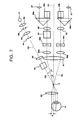
- FIG. 7 An arrangement state of the optical system after movement of the head lens 20 is shown in Fig. 7 .
- a displacement of an optical axis (a head lens optical axis) OF of the head lens 20 with respect to the observation optical axis O1 is denoted by symbol ⁇ .
- Fig. 8 shows an arrangement state before the head lens 20 is moved, namely, an arrangement state shown in Fig. 6 .
- Fig. 9 shows an arrangement state after the head lens 20 is moved by ⁇ , namely, an arrangement state shown in Fig. 7 .
- a light L1 passed through an aperture end of the illumination diaphragm 56 is partially reflected by a rear surface 20b (a lens face closer to the objective lens 31) of the head lens 20.
- This reflected light L2 travels toward the objective lens 31.
- the light L1 transmitted through the rear surface 20b is partially reflected by a surface 20a.
- This reflected light L3 travels toward the objective lens 31.
- a reflected light L2' by the rear surface 20b of the head lens 20 passes outside (the left side of) the objective lens 31.
- a reflected light L3' by the surface 20a also passes outside (the right side of) the objective lens 31.
- the examiner can regulate the position of the head lens 20 and the optical axis angle 0' while referring to the observation image of the fundus oculi Er, thereby seeking a favorable arrangement state as shown in Fig. 9 .
- the examiner moves the head lens 20 in the anteroposterior direction to focus with respect to the fundus oculi Er when necessary (S6, S7).
- the examiner looks through the eyepiece lens 37 to observe a magnified image of the fundus oculi Er (S8).
- the optical path of the left optical system may be interrupted so that a light having entered the left optical system is interrupted.
- the optical path can be interrupted by using any kind of member (an interrupting part) such as a diaphragm or a shutter.
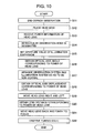
- FIG. 10 shows an example of the use aspect in this case.
- the head lens 20 When the cornea observation of the eye E ends (S11), the head lens 20 is placed between the eye E and the objective lens 31 (S12).
- the operation of placing the head lens 20 may be manually performed by the examiner, or may be performed by control of the head lens holder 14 by the controller 101.
- the controller 101 receives power information of the head lens 20 to be used (S13). For example, this power information is sent to the controller 101 by inputting the power (or the identification information) of the head lens 20 to be used with the manipulation part 104. Alternatively it is possible to configure so that each of the head lenses 20 is given unique information and the controller 101 acquires the power information by automatically reading this unique information.
- the examiner manipulates the manipulation part 104 to designate an intraocular observation mode (S14).
- a fundus oculi observation mode for observing the fundus oculi Er is designated.
- An observation mode represents the setup of each part and operation aspect of the slit lamp microscope 1 for observing a predetermined site (cornea, fundus oculi, and so on) of an eye.
- the controller 101 controls the illumination diaphragm 56 to set an aperture value (S51).
- the aperture value may be set with reference to the power information of the head lens 20 obtained at step 13.
- the relation between the power information and the aperture value is previously generated and stored into the storage 102, for example, like the aforementioned angle relation information 102a.
- the controller 101 controls the slit 54 to be kept open.
- the controller 101 Based on the power information of the head lens 20 and the angle relation information 102a, the controller 101 obtains an optical axis angle corresponding to a power represented in the power information (S16). Furthermore, based on this optical axis angle, the controller 101 controls the actuator 105 to move the illumination system 8, thereby arranging the observation system 6 and the illumination system 8 so as to be non-coaxial (nonparallel) (S17). Consequently, the observation system 6 and the illumination system 8 are arranged so that the optical axes O1 and O2 form the optical axis angle (refer to Figs. 5 and 6 ).
- the controller 101 based on the power information of the head lens 20 and the displacement relation information 102c, obtains a displacement (the optical axis displacement ⁇ ) in the lateral direction of the head lens 20 corresponding to the power represented in the power information (S18). Furthermore, the controller 101 controls the actuator 106 based on this optical axis displacement ⁇ to move the head lens 20 in the lateral direction (S19). Consequently, the head lens optical axis OF and the observation optical axis O1 are brought into a state separated by distance ⁇ (refer to Fig. 7 ).
- the head lens optical axis OF and the observation optical axis O1 shall match.
- the apparatus may be configured to be capable of detecting the position of the head lens 20 based on the state of the head lens holder 14 (the actuator) to thereby move the head lens 20 to a target position while monitoring a positional relation between the head lens optical axis OF and the observation optical axis O1.
- the position of the head lens 20 can also be detected by using another part such as a potentiometer.
- the controller 101 obtains a distance (a lens distance) between the head lens 20 and the objective lens 31 based on the power information of the head lens 20 and the distance relation information 102b (S20). Furthermore, the controller 101 controls the actuator 106 based on this lens distance to move the head lens 20 in the anteroposterior direction and focus with respect to the fundus oculi Er (S21).
- the examiner looks through the eyepiece lens 37 to observe a magnified image of the fundus oculi Er (S22).
- a reflection light by the fundus oculi Er enters only the optical system on the side of the illumination system 8 (on the right side), of the right and left optical systems of the observation system 6. Therefore, it is desirable that the examiner performs the fundus oculi observation with his/her left eye closed.
- the optical path of the left optical system may be interrupted so that a light having entered the left optical system is interrupted.
- the optical path can be interrupted by using any kind of member (an interrupting part) such as a diaphragm or a shutter.
- one or more of the setups may be manually switched. That is to say, although control of the aperture value of the illumination diaphragm 56, control of the operation of opening the slit 54, control of changing the optical axis angle, control of changing the optical axis displacement, control of changing the lens distance, and so on are automatically performed in the abovementioned use aspect, any of these setups can be manually performed.
- the case of manually setting has already been described in the use aspect shown in Fig. 4 .
- the optical axis angle, the optical axis displacement and the lens distance are obtained based on the power of the head lens 20, respectively, in the use aspect shown in Fig. 10 , part of these conditions may be kept constant regardless of the power and the remaining conditions may be obtained based on the power. At the time of obtaining the remaining conditions, the part of the conditions is also taken into consideration (that is to say, the part of the conditions is reflected on information generated in advance).
- a reverse process from the use aspect shown in Fig. 4 is performed.
- the examiner can cause the head lens 20 to retract from a position between the eye E and the objective lens 31, make the illumination diaphragm 56 open, change the optical axis angle as necessary, and change the position of the head lens 20 in the lateral direction and the anteroposterior direction as necessary.
- the examiner can also regulate the size (the slit width or the like) of the slit 54 as necessary.
- the controller 101 can cause the head lens 20 to retract, make the illumination diaphragm 56 open, change the optical axis angle to a predetermined default value, and change the position of the head lens 20 in the lateral direction and the anteroposterior direction to a predetermined default position.
- the controller 101 also can change the size (the slit width or the like) of the slit 54 to a predetermined default value (a slit size for the cornea observation).
- a predetermined default value a slit size for the cornea observation.
- the slit lamp microscope 1 acts to make an illumination light emitted from the illumination system 8 enter the inside of the eye E via the head lens 20 and make the intraocularly reflected light of the illumination light enter the observation system 6 via the head lens 20 in a state that the observation optical axis O1 and the illumination optical axis O2 are arranged so as to be nonparallel and the head lens optical axis OF and the optical axis of the objective lens 31 (the observation optical axis O1) are arranged so as to be separated in the lateral direction.
- the slit lamp microscope 1 it is possible to perform intraocular observation by using the illumination light propagated through the illumination diaphragm 56, so that it is possible to perform intraocular observation with a broader observation field than an observation field by a slit light as conventional. Since the aperture value of the illumination diaphragm 56 can be set to a maximum aperture value that reflection by the head lens 20 of the illumination light does not occur and vignetting of the illumination light by the pupil of the eye E does not occur, it is possible to obtain a sufficiently broader observation field than an observation field by a conventional slit light.
- an observation field by a conventional slit light is a rectangular region of about 6° ⁇ 18° in angle of view, but it is possible to obtain a circular observation field of about 30° in angle of view according to this embodiment. That is to say, what can be observed in one observation is, for example, only the optic papilla and neighborhood thereof of the fundus oculi Er in the conventional observation field, but it is possible to observe a broad range including the optical papilla and the macula in one observation according to this embodiment.
- the slit lamp microscope 1 is configured to, in intraocular observation of the eye E, make the intraocularly reflected light enter the right (left) optical system of the observation system 6 in a state that the illumination system 8 is arranged on the right (left) side of the observation system 6 and the head lens optical axis OF is arranged on the right (left) side of the optical axis O1 of the objective lens 31 (refer to Fig. 7 ).
- the examiner closes the other eye in order to avoid viewing a light entering the other optical system.
- the slit lamp microscope 1 is capable of interrupting the light having entered the other optical system with an interrupting part.
- An object of this embodiment is to obtain a broad observation field without causing flare.
- the slit lamp microscope 1 acts to obtain an optical axis angle corresponding to the power of the used head lens 20 with reference to the angle relation information 102a and, based on this optical axis angle, move the illumination system 8. Consequently, it is possible to easily set a favorable optical axis angle (the angle between the observation optical axis O1 and the illumination optical axis O2) for intraocular observation.
- the slit lamp microscope 1 is capable of obtaining a lens distance corresponding to the power of the used head lens 20 with reference to the distance relation information 102b and, based on this lens distance, move the head lens 20 in the anteroposterior direction to focus. Consequently, it is possible to easily focus with respect to an intraocular site to be observed.
- the focusing can be executed in a like manner as the automatic focus function of general cameras. Alternatively, it is possible to automatically focus by changing a distance between the head lens 20 and the objective lens 31 while analyzing an image captured by the imaging apparatus 13. Alternatively, it is also possible to configure to be capable of moving the observation system 6 in the anteroposterior direction with respect to the head lens 20.
- the slit lamp microscope 1 acts to obtain an optical axis displacement corresponding to the power of the used head lens 20 with reference to the displacement relation information 102c and, based on this optical axis displacement, move the head lens 20 in the lateral direction. Consequently, it is possible to easily set a favorable optical axis displacement (an interval between the observation optical axis O1 and the head lens optical axis OF) for intraocular observation.
- a fixing optical system that projects a fixation target to an eye is disposed to the observation system 6.
- the fixing optical system is specifically disposed to an optical system that guides the intraocularly reflected light of the illumination light.
- both the right and left optical systems are provided with the fixing optical systems, respectively.
- the fixing optical system is an example of a "projector" of the present invention.
- the fixing optical system includes, for example, a fixation target presenting part 61, a reflection mirror 62, and a beam splitter 63.
- the fixation target presenting part 61 presents a fixation target.
- the fixation target presenting part 61 includes a flat panel display such as an LCD, a lens, and so on.
- This flat panel display can display a fixation target at various positions on a display screen by control of the controller 101.
- the fixation target presenting part 61 in which a plurality of LEDs selectively turned on by the controller 101 are arranged.
- a light flux (a fixation target) outputted from the fixation target presenting part 61 is reflected by the reflection mirror 62 and guided to the beam splitter 63.
- the beam splitter 63 reflects this light flux and causes the light flux to travel toward the objective lens 31 along the optical axis OR. This light flux enters the eye E via the objective lens 31 and the head lens 20 and is projected to the fundus oculi Er (not shown in the drawing).
- the examiner gives a subject an instruction to stare this fixation target.
- the fixation target presenting part 61 By changing a position to present the fixation target by the fixation target presenting part 61, it is possible to make the eye E fix in various directions. Consequently, it is possible to change an intraocular site to be observed. For example, it is possible to observe the fundus oculi Er with an observation field about the optic papilla, observe the fundus oculi Er with an observation field about the macula, or observe the fundus oculi Er with an observation field about a lesion site.
- fixation lamp an external fixation lamp
- the optical axis of the head lens 20 and the optical axis of the objective lens 31 are arranged so as to be separate from each other.
- This modification example will describe a configuration example to arrange the optical axis of the head lens 20 and the optical axis of the objective lens 31 so as to be separate by changing a position to mount the head lens 20 on the head lens holder 14.
- Fig. 12 shows a configuration of the stereomicroscope according to this modified example.
- Fig. 12 is a view taken from the front (or the rear) of the head lens 20 and the head lens holder 14.
- the head lens 20 is set in a lens frame 21.
- a mount 22 for mounting the head lens holder 14 is attached. It is also possible to configure the lens frame 21 and the mount 22 in one body. The aspects of the lens frame 21 and the mount 22 are arbitrary.
- a mount 14a is disposed. On the top end of the mount 14a, a groove is formed along the lateral direction (not shown in the drawing). One end in the longitudinal direction of the mount 22 for the head lens 20 is connected to the lens frame 21, and the other end is inserted into the groove of the head lens holder 14. The groove acts to hold the mount 22.
- the head lens 20 is mounted on the head lens holder 14. It is also possible to dispose a member (a screw, an elastic member or the like) for holding the mount 22 so that the mount 22 inserted in the groove does not move.
- a plurality of head lenses 20 having different powers are selectively mounted.
- the head lens 20 is arranged off the observation optical axis O1 in the lateral direction and used for intraocular observation.
- the head lens holder 14 is provided with an indicator 14b that indicates the positions to mount the respective head lenses 20 to the mount 14a.
- the indicator 14b includes identification information of the head lens 20 and mounting position information. Symbols I, II and III shown in Fig. 12 denote examples of the identification information.
- the identification information may be the power of the head lens 20.
- the mounting position information is a line (a dotted line in Fig. 12 ) extending from the identification information to the top end of the mount 14a.
- the identification information and the mounting position information are given on both the sides in the lateral direction in consideration of both mounting the head lens 20 on the left side of the observation optical axis O1 and mounting the head lens 20 on the right side (that is, in consideration of both arranging the illumination system 8 on the left side and arranging the illumination system 8 on the right side, in other words, both observing with the left optical system of the observation system 6 and observing with the right optical system).
- the mount 14a is an example of a "mount” of the present invention.
- the indicator 14b is an example of an "indicator” of the present invention.
- the examiner manipulates the manipulation part 104 to move the head lens 20 with electric power, the examiner moves the head lens 20 to a position indicated by the indicator, thereby being capable of easily arranging the head lens 20 in a favorable position.
- the indicator can be adapted in order to determine the position (the optical axis angle) of the illumination system 8. For example, by disposing an indicator that indicates the position (the optical axis angle) of the illumination system 8 corresponding to each of the plurality of head lenses having different powers, to a first mechanism (supporting arm 17 and neighborhood positions), it is possible to easily set the optical axis angle.
- This indicator is formed by providing scales and letters to a position corresponding to a trajectory (arch-like) of the illumination system 8.
- a prism effect is caused by movement of the head lens 20 in the lateral direction, and an observation image is affected by aberration.
- ED glass low-dispersion optical glass
- image data obtained by intraocular imaging is analyzed.
- it is possible to correct aberration by adjusting the shape of an observation field to the shape of a cross section (for example, circular) of the illumination light.
- the method for correcting aberration is not limited to the abovementioned cross section shape, and it is possible to apply any known method.
- the observation system 6 may be provided with a diaphragm member (an observation diaphragm).
- the observation diaphragm effectively acts particularly in observation of the fundus oculi Er of the eye E.
- the observation diaphragm interrupts unnecessary light such as the reflected light of the illumination light by the cornea or crystalline lens.
- the aperture value of the observation diaphragm can be set in accordance with a condition such as the pupillary diameter of the eye E, for example.
- the observation diaphragm can be used as an interrupting part that interrupts a light having entered the observation system 6.
- the observation diaphragm is placed in any position of the observation system 6, for example, between the magnifying lenses 32a and 32b.
Landscapes
- Health & Medical Sciences (AREA)
- Life Sciences & Earth Sciences (AREA)
- Physics & Mathematics (AREA)
- Surgery (AREA)
- General Health & Medical Sciences (AREA)
- Engineering & Computer Science (AREA)
- Biomedical Technology (AREA)
- Heart & Thoracic Surgery (AREA)
- Medical Informatics (AREA)
- Molecular Biology (AREA)
- Biophysics (AREA)
- Animal Behavior & Ethology (AREA)
- Ophthalmology & Optometry (AREA)
- Public Health (AREA)
- Veterinary Medicine (AREA)
- Chemical & Material Sciences (AREA)
- Analytical Chemistry (AREA)
- General Physics & Mathematics (AREA)
- Optics & Photonics (AREA)
- Eye Examination Apparatus (AREA)
- Microscoopes, Condenser (AREA)
Applications Claiming Priority (2)
| Application Number | Priority Date | Filing Date | Title |
|---|---|---|---|
| JP2008051809A JP2009207590A (ja) | 2008-03-03 | 2008-03-03 | 実体顕微鏡 |
| PCT/JP2009/000648 WO2009110175A1 (fr) | 2008-03-03 | 2009-02-18 | Microscope stéréoscopique |
Publications (2)
| Publication Number | Publication Date |
|---|---|
| EP2248460A1 true EP2248460A1 (fr) | 2010-11-10 |
| EP2248460A4 EP2248460A4 (fr) | 2013-03-27 |
Family
ID=41055742
Family Applications (1)
| Application Number | Title | Priority Date | Filing Date |
|---|---|---|---|
| EP09716258A Withdrawn EP2248460A4 (fr) | 2008-03-03 | 2009-02-18 | Microscope stéréoscopique |
Country Status (4)
| Country | Link |
|---|---|
| US (1) | US8205988B2 (fr) |
| EP (1) | EP2248460A4 (fr) |
| JP (1) | JP2009207590A (fr) |
| WO (1) | WO2009110175A1 (fr) |
Cited By (5)
| Publication number | Priority date | Publication date | Assignee | Title |
|---|---|---|---|---|
| WO2013087872A1 (fr) | 2011-12-14 | 2013-06-20 | Universität Bern | Système d'optimisation d'image automatique, en particulier pour stéréomicroscopes |
| EP2695572A1 (fr) * | 2012-08-07 | 2014-02-12 | Kabushiki Kaisha Topcon | Microscope de lampe à fente |
| EP2695571A1 (fr) * | 2012-08-08 | 2014-02-12 | Kabushiki Kaisha Topcon | Microscope de lampe à fente |
| EP2721995A4 (fr) * | 2011-06-14 | 2014-11-26 | Topcon Corp | Microscope à lampe à fente |
| US20260026687A1 (en) * | 2023-11-07 | 2026-01-29 | Lightfield Medical Inc. | Methods for analyzing the eye |
Families Citing this family (24)
| Publication number | Priority date | Publication date | Assignee | Title |
|---|---|---|---|---|
| US9158106B2 (en) | 2005-02-23 | 2015-10-13 | Pixtronix, Inc. | Display methods and apparatus |
| US20070205969A1 (en) | 2005-02-23 | 2007-09-06 | Pixtronix, Incorporated | Direct-view MEMS display devices and methods for generating images thereon |
| US9261694B2 (en) | 2005-02-23 | 2016-02-16 | Pixtronix, Inc. | Display apparatus and methods for manufacture thereof |
| US9229222B2 (en) | 2005-02-23 | 2016-01-05 | Pixtronix, Inc. | Alignment methods in fluid-filled MEMS displays |
| US8519945B2 (en) | 2006-01-06 | 2013-08-27 | Pixtronix, Inc. | Circuits for controlling display apparatus |
| US8310442B2 (en) | 2005-02-23 | 2012-11-13 | Pixtronix, Inc. | Circuits for controlling display apparatus |
| US9082353B2 (en) * | 2010-01-05 | 2015-07-14 | Pixtronix, Inc. | Circuits for controlling display apparatus |
| US7999994B2 (en) | 2005-02-23 | 2011-08-16 | Pixtronix, Inc. | Display apparatus and methods for manufacture thereof |
| US8526096B2 (en) | 2006-02-23 | 2013-09-03 | Pixtronix, Inc. | Mechanical light modulators with stressed beams |
| US9176318B2 (en) | 2007-05-18 | 2015-11-03 | Pixtronix, Inc. | Methods for manufacturing fluid-filled MEMS displays |
| US8169679B2 (en) | 2008-10-27 | 2012-05-01 | Pixtronix, Inc. | MEMS anchors |
| DE102009058792B3 (de) * | 2009-12-18 | 2011-09-01 | Carl Zeiss Surgical Gmbh | Optische Beobachtungseinrichtung zur Beobachtung eines Auges |
| BR112012019383A2 (pt) | 2010-02-02 | 2017-09-12 | Pixtronix Inc | Circuitos para controlar aparelho de exibição |
| JP5794664B2 (ja) * | 2011-01-20 | 2015-10-14 | キヤノン株式会社 | 断層画像生成装置及び断層画像生成方法 |
| DE102012216470B4 (de) * | 2012-09-14 | 2021-01-28 | Leica Microsystems (Schweiz) Ag | Spaltleuchte für ein Operationsmikroskop und Operationsmikroskop |
| US9134552B2 (en) | 2013-03-13 | 2015-09-15 | Pixtronix, Inc. | Display apparatus with narrow gap electrostatic actuators |
| JP2016174758A (ja) * | 2015-03-20 | 2016-10-06 | 株式会社トプコン | 細隙灯顕微鏡 |
| JP2016174759A (ja) * | 2015-03-20 | 2016-10-06 | 株式会社トプコン | 細隙灯顕微鏡 |
| JP2016179004A (ja) * | 2015-03-24 | 2016-10-13 | 株式会社トプコン | スリットランプ顕微鏡及びその制御方法 |
| JP7042663B2 (ja) * | 2017-03-30 | 2022-03-28 | 株式会社トプコン | 眼科用顕微鏡 |
| JP7548565B2 (ja) * | 2018-03-16 | 2024-09-10 | レミディオ・イノベイティブ・ソリューションズ・プライベート・リミテッド | 後眼領域および前眼領域を撮像するための眼部撮像デバイス |
| CN111035359A (zh) * | 2019-12-28 | 2020-04-21 | 重庆贝奥新视野医疗设备有限公司 | 一种立体成像眼底照相机系统 |
| CA3238012A1 (fr) * | 2021-11-12 | 2023-05-19 | Robert T. Hewlett | Systeme de microscope chirurgical |
| CN119896445B (zh) * | 2025-03-26 | 2025-06-27 | 视微影像(河南)科技有限公司 | 激光发射装置与眼科系统 |
Family Cites Families (16)
| Publication number | Priority date | Publication date | Assignee | Title |
|---|---|---|---|---|
| US2999422A (en) * | 1956-12-28 | 1961-09-12 | Haag Streit A G | Slit lamp |
| US4478499A (en) * | 1981-09-30 | 1984-10-23 | Carl-Zeiss-Stiftung, Heidenheim/Brenz | Operation microscope with fixation device |
| US4699481A (en) * | 1984-09-01 | 1987-10-13 | Canon Kabushiki Kaisha | Stereoscopic microscope |
| DE4326761A1 (de) * | 1993-08-10 | 1995-02-16 | Zeiss Carl Fa | Stereomikroskop |
| JPH09276227A (ja) | 1996-04-10 | 1997-10-28 | Nikon Corp | レンズホルダーを備えた細隙灯顕微鏡 |
| JP4476406B2 (ja) * | 2000-01-18 | 2010-06-09 | 株式会社トプコン | 実体顕微鏡 |
| JP4554027B2 (ja) * | 2000-03-31 | 2010-09-29 | 株式会社トプコン | 眼科装置 |
| JP4068371B2 (ja) * | 2001-06-13 | 2008-03-26 | 株式会社トプコン | 手術用顕微鏡 |
| JP4068101B2 (ja) | 2001-06-13 | 2008-03-26 | 株式会社トプコン | 手術用顕微鏡 |
| JP2003024366A (ja) | 2001-07-16 | 2003-01-28 | Kiyoshi Kita | 眼科手術用コンタクトレンズ |
| JP3756127B2 (ja) * | 2002-04-19 | 2006-03-15 | 株式会社トプコン | 眼科撮影装置 |
| KR101092108B1 (ko) * | 2003-02-17 | 2011-12-12 | 가부시키가이샤 토프콘 | 수술용 현미경 |
| JP4717360B2 (ja) * | 2003-02-17 | 2011-07-06 | 株式会社トプコン | 手術用顕微鏡 |
| JP2005034285A (ja) * | 2003-07-18 | 2005-02-10 | Topcon Corp | 手術用顕微鏡及び観察プリズム |
| JP4531413B2 (ja) | 2004-02-10 | 2010-08-25 | 株式会社トプコン | 細隙灯顕微鏡 |
| JP2006296806A (ja) * | 2005-04-21 | 2006-11-02 | Topcon Corp | 手術用顕微鏡装置 |
-
2008
- 2008-03-03 JP JP2008051809A patent/JP2009207590A/ja active Pending
-
2009
- 2009-02-18 EP EP09716258A patent/EP2248460A4/fr not_active Withdrawn
- 2009-02-18 WO PCT/JP2009/000648 patent/WO2009110175A1/fr not_active Ceased
- 2009-02-18 US US12/736,029 patent/US8205988B2/en not_active Expired - Fee Related
Cited By (7)
| Publication number | Priority date | Publication date | Assignee | Title |
|---|---|---|---|---|
| EP2721995A4 (fr) * | 2011-06-14 | 2014-11-26 | Topcon Corp | Microscope à lampe à fente |
| US9364146B2 (en) | 2011-06-14 | 2016-06-14 | Kabushiki Kaisha Topcon | Slit lamp microscope |
| WO2013087872A1 (fr) | 2011-12-14 | 2013-06-20 | Universität Bern | Système d'optimisation d'image automatique, en particulier pour stéréomicroscopes |
| US9277861B2 (en) | 2011-12-14 | 2016-03-08 | Universität Bern | Automatic image optimization system, particularly for stereomicroscopes |
| EP2695572A1 (fr) * | 2012-08-07 | 2014-02-12 | Kabushiki Kaisha Topcon | Microscope de lampe à fente |
| EP2695571A1 (fr) * | 2012-08-08 | 2014-02-12 | Kabushiki Kaisha Topcon | Microscope de lampe à fente |
| US20260026687A1 (en) * | 2023-11-07 | 2026-01-29 | Lightfield Medical Inc. | Methods for analyzing the eye |
Also Published As
| Publication number | Publication date |
|---|---|
| US8205988B2 (en) | 2012-06-26 |
| US20100328608A1 (en) | 2010-12-30 |
| JP2009207590A (ja) | 2009-09-17 |
| WO2009110175A1 (fr) | 2009-09-11 |
| EP2248460A4 (fr) | 2013-03-27 |
Similar Documents
| Publication | Publication Date | Title |
|---|---|---|
| US8205988B2 (en) | Stereomicroscope | |
| US9364146B2 (en) | Slit lamp microscope | |
| JP4417035B2 (ja) | 観察装置 | |
| EP1447698B1 (fr) | Microscope d'opération ophthalmique | |
| JP6812724B2 (ja) | 眼科手術システム、眼科手術システム制御プログラム、および眼科用手術顕微鏡 | |
| US7990610B2 (en) | Stereomicroscope with repositioning assistant's microscope | |
| JP2008093433A (ja) | 眼科用手術顕微鏡システム | |
| JP6518126B2 (ja) | 細隙灯顕微鏡 | |
| JP5090807B2 (ja) | 手術用顕微鏡装置 | |
| US6072623A (en) | Slit lamp microscope | |
| JP2016174759A (ja) | 細隙灯顕微鏡 | |
| JP7002817B2 (ja) | 前置レンズ装置及び眼科用顕微鏡 | |
| US20220175245A1 (en) | Eye examination attachment, control device, and ophthalmic microscope system | |
| WO2011064943A1 (fr) | Microscope pour chirurgie oculaire | |
| US7393103B2 (en) | Operation microscope apparatus | |
| JP2012152361A (ja) | 乱視軸測定装置、及び眼科装置 | |
| JP6090977B2 (ja) | 眼科用検査装置 | |
| WO2019066027A1 (fr) | Dispositif de lentille frontale et microscope ophtalmique | |
| JP6912230B2 (ja) | 眼科装置 | |
| JP6003234B2 (ja) | 眼底撮影装置 | |
| JP2019092725A (ja) | 前置レンズ装置及び眼科用顕微鏡 | |
| JP2019092844A (ja) | 前置レンズ装置及び眼科用顕微鏡 | |
| JP2580500B2 (ja) | 角膜内皮細胞撮影装置 | |
| JP6098094B2 (ja) | 眼科装置 | |
| US20240074649A1 (en) | Ophthalmic apparatus, method of controlling ophthalmic apparatus, and recording medium |
Legal Events
| Date | Code | Title | Description |
|---|---|---|---|
| PUAI | Public reference made under article 153(3) epc to a published international application that has entered the european phase |
Free format text: ORIGINAL CODE: 0009012 |
|
| 17P | Request for examination filed |
Effective date: 20100824 |
|
| AK | Designated contracting states |
Kind code of ref document: A1 Designated state(s): AT BE BG CH CY CZ DE DK EE ES FI FR GB GR HR HU IE IS IT LI LT LU LV MC MK MT NL NO PL PT RO SE SI SK TR |
|
| AX | Request for extension of the european patent |
Extension state: AL BA RS |
|
| DAX | Request for extension of the european patent (deleted) | ||
| A4 | Supplementary search report drawn up and despatched |
Effective date: 20130221 |
|
| RIC1 | Information provided on ipc code assigned before grant |
Ipc: A61B 19/00 20060101ALI20130215BHEP Ipc: A61B 3/12 20060101AFI20130215BHEP Ipc: G02B 21/00 20060101ALI20130215BHEP |
|
| STAA | Information on the status of an ep patent application or granted ep patent |
Free format text: STATUS: THE APPLICATION IS DEEMED TO BE WITHDRAWN |
|
| 18D | Application deemed to be withdrawn |
Effective date: 20130924 |