EP2248479B1 - Ensemble formant une lame osseuse - Google Patents
Ensemble formant une lame osseuse Download PDFInfo
- Publication number
- EP2248479B1 EP2248479B1 EP10162215A EP10162215A EP2248479B1 EP 2248479 B1 EP2248479 B1 EP 2248479B1 EP 10162215 A EP10162215 A EP 10162215A EP 10162215 A EP10162215 A EP 10162215A EP 2248479 B1 EP2248479 B1 EP 2248479B1
- Authority
- EP
- European Patent Office
- Prior art keywords
- screw
- plate
- bone
- threads
- bone plate
- Prior art date
- Legal status (The legal status is an assumption and is not a legal conclusion. Google has not performed a legal analysis and makes no representation as to the accuracy of the status listed.)
- Active
Links
Images





Classifications
-
- A—HUMAN NECESSITIES
- A61—MEDICAL OR VETERINARY SCIENCE; HYGIENE
- A61B—DIAGNOSIS; SURGERY; IDENTIFICATION
- A61B17/00—Surgical instruments, devices or methods
- A61B17/56—Surgical instruments or methods for treatment of bones or joints; Devices specially adapted therefor
- A61B17/58—Surgical instruments or methods for treatment of bones or joints; Devices specially adapted therefor for osteosynthesis, e.g. bone plates, screws or setting implements
- A61B17/68—Internal fixation devices, including fasteners and spinal fixators, even if a part thereof projects from the skin
- A61B17/84—Fasteners therefor or fasteners being internal fixation devices
- A61B17/86—Pins or screws or threaded wires; nuts therefor
- A61B17/8605—Heads, i.e. proximal ends projecting from bone
-
- A—HUMAN NECESSITIES
- A61—MEDICAL OR VETERINARY SCIENCE; HYGIENE
- A61B—DIAGNOSIS; SURGERY; IDENTIFICATION
- A61B17/00—Surgical instruments, devices or methods
- A61B17/56—Surgical instruments or methods for treatment of bones or joints; Devices specially adapted therefor
- A61B17/58—Surgical instruments or methods for treatment of bones or joints; Devices specially adapted therefor for osteosynthesis, e.g. bone plates, screws or setting implements
- A61B17/68—Internal fixation devices, including fasteners and spinal fixators, even if a part thereof projects from the skin
- A61B17/80—Cortical plates, i.e. bone plates; Instruments for holding or positioning cortical plates, or for compressing bones attached to cortical plates
- A61B17/8052—Cortical plates, i.e. bone plates; Instruments for holding or positioning cortical plates, or for compressing bones attached to cortical plates immobilised relative to screws by interlocking form of the heads and plate holes, e.g. conical or threaded
- A61B17/8057—Cortical plates, i.e. bone plates; Instruments for holding or positioning cortical plates, or for compressing bones attached to cortical plates immobilised relative to screws by interlocking form of the heads and plate holes, e.g. conical or threaded the interlocking form comprising a thread
Definitions
- the present invention is related generally to implantable orthopedic implants. More specifically, the present invention is related to implantable orthopedic bone plates used to reinforce fractured bones.
- Orthopedic bone plates play a critical role in the healing process of broken bones. Once a bone has been fragmented, it is ideal for the broken bone fragments to be joined back together under compression to promote improved healing.
- the bone plate is a critical device that is used as a stabilizing bar to bridge the gap between bone fragments.
- a bone plate is inserted next to the fragmented bone of a patient.
- Compression screws are first placed through the bone plate. They are anchored into each of the bone fragments and tightened, pulling the bone fragments together under a compression load and against the plate. Once the compression screws are set in place, locking bone screws are inserted through the bone plate and anchored into the fragmented bone.
- the locking screws in conjunction with the bone plate secure the bone fragments together and the compression created by the compression screws ensures that they do not move.
- high tensile stresses are created when the bone fragments are fixated with the locking screws. These tensile stresses could damage the fragile bone fragments and impair the healing process. Bone plates, therefore, are a key element in the bone healing process.
- Bone fragmentation is unpredictable. As a result of a traumatic experience, a bone may fragment in multiple erratic locations and present itself in random orientations. Every patient's bones are unique; no two bones will fragment in the same manner in the same orientation. Nevertheless, traditional bone plate technology makes it difficult for a bone plate to be oriented in such a manner as to be utilized correctly for every trauma situation.
- Bone plates are rigid braces, typically composed of metal, which have historically been designed with fixed threaded holes through which some bone screws may not properly align with the matching bone fragment.
- early bone plate technology comprised bone plates with preexisting threaded holes in combination with threaded locking screws. These earlier bone plates often lacked the ability to secure bone fragments that were not aligned under the threaded screw holes. That is because the preexisting threaded holes of earlier bone plate technology confined the angle through which the locking screw could be advanced into a bone fragment.
- an orthopedic device that expands the possible locking screw insertion angles in anchoring bone fragments to promote bone healing.
- DE 4343117 describes a fixation system for bones comprising a bone plate with at least one bore in which is set a bone screw.
- WO 2008/007196 describes a bone plate which is adapted for use in situ to fix a spatial relationship of at least two bone parts.
- US 2008/234677 describes a multi-angular fastening bone screw/plate system that comprises a plate or other component suitable for affixation by a fastener.
- US 2008/140130 describes a bone plate system for internal fixation of bone fractures which includes a bone plate having a plurality of bone plate holes.
- the present invention is directed to an orthopedic bone plate system comprising a compression screw, a locking screw, and a bone plate with a plurality of complex locking screw apertures.
- the inner wall of the bone plate is provided with a plurality of thread columns separated from each other by relief notches.
- the head of the locking screw is provided with a plurality of thread columns separated from each other by relief notches.
- FIG. 1 is a perspective view of an orthopedic bone plate system 10 according to the present invention.
- the bone plate system 10 comprises a bone plate 12 and at least one locking screw 14. If desired, at least one compression screw 15 can also be included.
- the bone plate 12 has a longitudinal axis A-A, an axis B-B ( FIG. 3 ) which is oriented 90 degrees from axis A-A, a bone contacting bottom side 20 and a top side 22.
- At least one complex aperture 24 extends through the bone plate 12 from the top side 22 to the bottom side 20.
- the complex aperture 24 is designed to receive either the locking screw 14 or the compression screw 15.
- the complex aperture 24 is comprised of at least one set of two immediately adjacent apertures 26, 28. The apertures 26, 28 do not overlap, thereby providing the complex aperture 24 as an oval shaped opening.
- FIG. 2 shows an enlarged perspective view of the complex aperture 24.
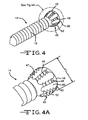
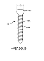
- the plan view of the complex aperture 24 illustrated in FIG. 3 shows that apertures 26, 28 have a center-to-center distance d along the longitudinal axis A-A that is greater than the diameter d 1 of the head of the locking screw 14 ( FIG. 4A ) or d 2 of the head of the compression screw 15 ( FIG. 9 ). That way, the adjacent apertures 26, 28 of the complex aperture 24 define a relief-space 30 disposed between them.
- the relief-space 30 is configured as either a straight slot, or as a constricted or "waisted" slot centered along axes A-A and bisected by axis B-B.
- a compression ramp surface 38 emerges into the complex aperture 24 from opposite sides of the wall 34 of the bone plate 12 to provide part of the boundary for the relief-space 30.
- the compression ramp surfaces 38 are non-threaded and ramp into the open relief space 30 of the complex aperture 24 along both the axis B-B perpendicular to the longitudinal axis A-A of the bone plate 12 and into the open space of the openings 26, 28 themselves.
- the ramp surfaces 38 slope downwardly and inwardly from the bone plate top side surface 22 into the opening of the complex aperture 24.
- the distal end of each of the ramps 38 meets a substantially vertical surface 40 which extends to the bone plate bottom side 20.
- the ramps 38 meet threaded surfaces of the openings.
- Vertical surface 40 can be planar or have a beveled contour that ramp into the open spaces 30 and into each of the apertures 26, 28 of the complex aperture 24.
- the downwardly and inwardly sloping ramps 38 act as compression structures for the locking screw 14. As the locking screw 14 is threaded into one of the apertures 26 or 28 comprising the complex aperture 24 and moves in a downwardly direction, the underside of the locking screw head 16 compresses against the ramp surface 38. The downwardly sloping inclination of the ramp 38 causes the screw head 16 to slide down the ramp 38, creating a frictional fit and prohibiting advancement of the locking screw 14 further into the complex aperture 24.
- the plate threads 31 are aligned in a spiral extending from adjacent to the top side 22 toward the bottom side 20.
- the spiral of the plate threads 31 has a pitch that ranges from about 0.1 mm. to about 1.0 mm.
- the plate threads 31 are also orientated in thread columns 32, 33, etc. ( FIGs. 6 to 8 ).
- Each thread column 32, 33 extends along the interior aperture wall surface 34 from the top side 22 to the bottom side 20 of plate 12.
- the thread columns 32, 33 are preferably spaced apart from each other by a distance ranging from about 0.10 mm. to about 0.500 mm.
- each thread column 32, 33 is defined as an aperture relief notch 36 in the form of an indentation into the wall of the bone plate 12 defining the apertures 26, 28 of the complex aperture 24.
- Each complex aperture 24 may comprise multiple relief notches 36 having exemplary shapes including curved, squared-off or as a key slot. In that manner, the threads 31 of the bone plate 12 provide both spiral and columnar structures.
- the locking screw 14 is comprised of a bulbous head 16 and an elongated shaft 18.
- the locking screw head 16 is comprised of locking threads that are generally indicated by numerical designation 45.
- the threads have a pitch similar to that of the threads 31 of the bone plate 12.
- the screw threads 45 are also aligned in a series of threaded columns 46, 48, 50, 52, etc. When viewed from the side, the locking threads 45 are separated from each other by a "V" cutout 47. It is in the space provided by the V-cutouts 47 that the threads 31 of the bone plate 12 reside as the screw 14 is threaded into the bone plate.
- a screw relief notch 60 is provided between adjacent columns of locking threads 45. The relief notches 60 extend from the locking screw head proximal end to the locking screw head distal end adjacent to the threaded shaft 18.
- FIG. 5 illustrates two exemplary orientations of locking screws 14 threaded in the bone plate 12.
- the right one is at about 90 degrees with respect to the longitudinal plane of the bone plate 12 while the left locking screw 14 is at an insertion angle of about 10° in relation to the longitudinal plane.
- Insertion angles can range from about 1° to about 45°, however, they preferably range from about 10° to about 40°, and more preferably from about 15° to about 35° from perpendicular.
- This figure is an exemplary illustration of the many orientations that the locking screw 14 can be inserted into the bone plate 12.
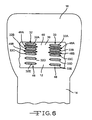
- FIGs. 6 , 7 and 8 illustrate how the present bone plate 12 and locking screw 14 system 10 allows the threads of the locking screw head 16 to bypass or "jump" threads on the bone plate. That the threads of the locking screw head 16 are capable of "jumping" threads of the bone plate 12 is made possible by the incorporation of the respective relief notches 36, 60 in both the bone plate apertures 26, 28 of the complex aperture 24 and in the locking screw head 16.
- screw threads in column 46 and 48 reside between thread columns 32 and 33, respectively, of the bone plate.
- the threads of the bone plate columns 32, 33 reside in the cutouts 47 provided between the thread columns 46, 48 of the screw 14.
- screw thread 46A resides between bone plate threads 32A and 32B and screw thread 46B resides between bone plate threads 32B and 32C.
- screw thread 48A resides between bone plate threads 33A and 33B and screw thread 48B resides between bone plate thread 33B and 33C.
- the relief notch 36 of the bone screw 12 resides between screw thread columns 32 and 33 and relief notch 60 of the plate 12 resides between plate thread columns 46 and 48.
- plate thread 33A is at a slightly lower elevation than plate thread 32A as the screw 16 is advancing into the bone plate. That is regardless whether the locking screw 14 is at an initial orientation perpendicular to the longitudinal plane of the plate as in the right-hand screw shown in FIG. 5 or at some other angular orientation as shown in the left-hand screw in that drawing.
- FIG. 7 illustrates how the locking screw threads bypass or "jump" levels of bone plate threads.
- a lateral force 100 has been applied to the locking screw head 16.
- This lateral force 100 is illustrated by showing that the longitudinal axis of the screw 16 has deviated an angle ⁇ . This angle is measured by the difference between the longitudinal axis 102 of the screw prior to the lateral force 100 in relation to the orientation of the axis 104 after the lateral force.
- the lateral force 100 would be imparted to the screw as the screw is simultaneously being threaded into the bone plate.
- exemplary locking screw thread 46A has moved laterally and downwardly, bypassing or "jumping" from where it would have resided between bone plate threads 33A and 33B had the lateral force 100 not occurred to being angled toward a position residing between bone plate threads 33B and 33C ( FIG. 8 ).
- This lateral force can only be exerted against the screw 14 when its columns of threads reside in the notches 36 of the bone plate 12. That is when the leading edge of a screw thread, for example threads 46A and 46B, is not engaged with either thread column 32 or 33 of the bone plate. However, the trailing edge of the screw threads 46A, 46B are still disposed between bone plate threads 32A, 32B and 32B, 32C, respectively. Otherwise, the bone screw 14 would be capable of simply “falling” through the bone plate every time the columns of threads 46, 48, 50, 52, 54, etc. on the screw 14 are in alignment with the relief notches 36 of the plate 12.
- each thread 45 comprising the thread columns 46, 48, 50 52, 54, etc. of the screw 14 are laterally from about .5 to 2 millimeters wider than the width of the bone plate relief notches 36.
- exemplary screw thread 46A has its leading edge just beginning to reside between the edges of plate threads 33B, 33C before the trailing edge of that thread has left the edges of plate threads 32A, 32B. That is from a longitudinal perspective with respect to the edges of the threads of the plate 12 and of the screw 14 as shown by dashed lines 106 and 108.
- the present plate and screw system 10 permits the physician to change the angle of the screw 14 part way through it being screwed into the plate 12, that should not be viewed as limiting.
- the screw 14 could be oriented with the threads of the bone plate 12 in the orientation shown in FIG. 8 . That is in a "jumped" or cross-threaded orientation from the beginning.
- the sequence of drawings of FIGs. 6 to 8 shown that the angle ⁇ can be increased so that the screw ends at a greater angle of inclination that which it was first oriented ( FIG. 6 ), the angle could also be decreased.
- the compression screw 15 illustrated in FIG. 9 can also be used with the bone plate 12 of the present invention.
- the compression screw 15 has shaft threads 15A that are helically disposed around the shaft 15B.
- An unthreaded head 15C is affixed to the proximal end of the shaft 15B.
- the bone plate 12 and locking and compression screws 14, 15 are preferably made from Ti 6A1-4V.
- other biocompatible materials not limited to other titanium alloys, stainless steel or polymers, i.e., PEEK could also be used.
- FIG. 1 further illustrates that the bone plate can comprise a threaded aperture 110 adapted to receive only one screw or an overlapping threaded aperture 112.
- the overlapping threaded aperture is similar to that described in U.S. Patent No. 7,695,472 to Young .
- the complex aperture 112 comprises at least two overlapping holes having an offset of a given distance between centers thereof, wherein any two immediately adjacent overlapping holes comprise a compression ramp extending from an oval shaped opening at the top side of the plate downwardly and inwardly part way through the plate thickness to a threaded lower portion having an hourglass shape extending from where the compression ramp ends at the hourglass shape to the bottom side of the bone plate with threaded surfaces of the overlapping holes meeting each other at a threaded overlap forming the hourglass shape, wherein the threaded lower portion is adapted to lock with threads of a corresponding bone screw in one or the other of the overlapping holes.
- the overlapping holes can be formed either normal to the top side of the plate or at an angle offset from normal. In either embodiment 110, 112, the aperture has a relief notches disposed between columns of threads as described with respect to the complex aperture 24.
Landscapes
- Health & Medical Sciences (AREA)
- Orthopedic Medicine & Surgery (AREA)
- Surgery (AREA)
- Life Sciences & Earth Sciences (AREA)
- Heart & Thoracic Surgery (AREA)
- Nuclear Medicine, Radiotherapy & Molecular Imaging (AREA)
- Engineering & Computer Science (AREA)
- Biomedical Technology (AREA)
- Neurology (AREA)
- Medical Informatics (AREA)
- Molecular Biology (AREA)
- Animal Behavior & Ethology (AREA)
- General Health & Medical Sciences (AREA)
- Public Health (AREA)
- Veterinary Medicine (AREA)
- Surgical Instruments (AREA)
Claims (9)
- Système de lame osseuse (10), qui comprend :a) une lame allongée (12) ayant un axe longitudinal (A-A), un côté inférieur de contact avec un os (20), un côté supérieur (22), une épaisseur entre le côté supérieur (22) et le côté inférieur (20) et au moins une ouverture de vis filetée (24) ayant des filets de lame (31) et s'étendant à travers son épaisseur ;b) une vis (14) comprenant une tige filetée (18) supportant une tête (16) dotée de filets de tête de vis (45), dans laquelle les filets de la tige de vis (18) sont adaptés pour se fileter dans un os et les filets (45) sur la tête de vis (16) sont adaptés pour s'accoupler de manière filetée aux filets de lame (31) ;c) dans lequel les filets de lame (31) sont dotés d'un pas et comprennent une première pluralité de colonnes filetées (32, 33) séparées par des premières encoches intermédiaires de dégagement (36) ; etd) dans lequel les filets de tête de vis (45) sont dotés d'un pas s'adaptant sensiblement au pas des filets de lame (31) et comprennent une seconde pluralité de colonnes filetées (46, 48, 50, 52, 54) séparées par des secondes encoches intermédiaires de dégagement (60) ;caractérisé en ce qu'une largeur de chaque filet (45) comprenant la seconde pluralité de colonnes filetées (46, 48, 50, 52, 54) de la vis (14) est d'environ 0,5 à 2 millimètres plus large que la largeur des premières encoches intermédiaires de dégagement (36) de la lame (12).
- Système de lame osseuse selon la revendication 1, dans lequel la première pluralité de colonnes filetées (32, 33) s'étend depuis une zone adjacente au côté supérieur (22) vers le côté inférieur (20) de la lame osseuse (12).
- Système de lame osseuse selon la revendication 1 ou la revendication 2, dans lequel la seconde pluralité de colonnes filetées (46, 48, 50, 52, 54) s'étend sensiblement le long d'un axe longitudinal de la vis (14).
- Système de lame osseuse selon l'une quelconque des revendications 1 à 3, dans lequel au moins une ouverture (110) dans la lame (12) est dimensionnée de façon à ne recevoir qu'une vis (14).
- Système de lame osseuse selon l'une quelconque des revendications 1 à 4, dans lequel au moins une ouverture dans la lame (12) est une ouverture complexe (24) comprenant une première et une seconde ouvertures filetées (26, 28) séparées l'une de l'autre par une zone de dégagement (30).
- Système de lame osseuse selon l'une quelconque des revendications 1 à 5, dans lequel au moins une ouverture dans la lame (12) est une ouverture complexe (112) s'étendant à travers l'épaisseur de la lame et comprenant au moins deux trous se chevauchant ayant un décalage d'une distance donnée entre leurs centres, dans lequel deux trous se chevauchant immédiatement adjacents quelconques comprennent une rampe de compression s'étendant depuis une ouverture de forme ovale sur le côté supérieur de la lame vers le bas et vers l'intérieur partiellement à travers l'épaisseur de la lame vers une partie inférieure filetée ayant une forme de sablier s'étendant depuis l'endroit où se termine la rampe de compression à la forme de sablier vers le côté inférieur (20) de la lame osseuse (12) avec des surfaces filetées des trous se chevauchant qui se rencontrent l'une l'autre au niveau d'un chevauchement fileté formant le sablier, dans lequel la partie inférieure filetée est adaptée pour se bloquer avec des filets d'une vis osseuse correspondante (14) dans l'un ou l'autre des trous se chevauchant.
- Système de lame osseuse selon l'une quelconque des revendications 1 à 6, dans lequel la lame (12) et la vis (14) sont fabriquées à partir d'un polymère ou d'un métal biocompatible.
- Système de lame osseuse selon l'une quelconque des revendications 1 à 7, dans lequel la lame (12) et la vis (14) font partie d'un kit.
- Système de lame osseuse selon la revendication 8, dans lequel le kit comprend à la fois une vis de blocage (14) et une vis de compression (15).
Applications Claiming Priority (1)
| Application Number | Priority Date | Filing Date | Title |
|---|---|---|---|
| US17585509P | 2009-05-06 | 2009-05-06 |
Publications (2)
| Publication Number | Publication Date |
|---|---|
| EP2248479A1 EP2248479A1 (fr) | 2010-11-10 |
| EP2248479B1 true EP2248479B1 (fr) | 2012-09-19 |
Family
ID=42288535
Family Applications (1)
| Application Number | Title | Priority Date | Filing Date |
|---|---|---|---|
| EP10162215A Active EP2248479B1 (fr) | 2009-05-06 | 2010-05-06 | Ensemble formant une lame osseuse |
Country Status (2)
| Country | Link |
|---|---|
| US (1) | US8337535B2 (fr) |
| EP (1) | EP2248479B1 (fr) |
Families Citing this family (81)
| Publication number | Priority date | Publication date | Assignee | Title |
|---|---|---|---|---|
| US8518090B2 (en) | 2010-10-05 | 2013-08-27 | Acumed Llc | Fastener with serrated thread for attachment to a bone plate at a selectable angle |
| US7951176B2 (en) | 2003-05-30 | 2011-05-31 | Synthes Usa, Llc | Bone plate |
| DE20321552U1 (de) | 2003-08-26 | 2007-12-27 | Synthes Gmbh | Knochenplatte |
| US11259851B2 (en) | 2003-08-26 | 2022-03-01 | DePuy Synthes Products, Inc. | Bone plate |
| US8574268B2 (en) | 2004-01-26 | 2013-11-05 | DePuy Synthes Product, LLC | Highly-versatile variable-angle bone plate system |
| US11291484B2 (en) | 2004-01-26 | 2022-04-05 | DePuy Synthes Products, Inc. | Highly-versatile variable-angle bone plate system |
| US8366719B2 (en) | 2009-03-18 | 2013-02-05 | Integrated Spinal Concepts, Inc. | Image-guided minimal-step placement of screw into bone |
| EP2477566B1 (fr) | 2009-09-14 | 2017-03-22 | Synthes GmbH | Plaque de compression à angle variable |
| BR112012033588A2 (pt) | 2010-07-21 | 2016-11-29 | Synthes Gmbh | dispositivo para osteossíntese. |
| US8753396B1 (en) * | 2010-09-13 | 2014-06-17 | Theken Spine, Llc | Intervertebral implant having back-out prevention feature |
| US8672978B2 (en) * | 2011-03-04 | 2014-03-18 | Zimmer Spine, Inc. | Transverse connector |
| WO2013036362A1 (fr) | 2011-09-06 | 2013-03-14 | Synthes Usa, Llc | Plaque vissée pour arthrodèse pancarpienne |
| DE202011106835U1 (de) * | 2011-10-14 | 2012-02-06 | Königsee Implantate GmbH | Knochenplatte |
| WO2013059090A1 (fr) * | 2011-10-17 | 2013-04-25 | Biomet Trauma, LLC | Système de placage d'os à verrouillage variable |
| WO2013095756A1 (fr) * | 2011-12-20 | 2013-06-27 | Synthes Usa, Llc | Caractéristique d'auto-centrage pour un clou centromédullaire |
| US20140066998A1 (en) * | 2012-09-06 | 2014-03-06 | Jean-Jacques Martin | Assembly comprising an implantable part designed to be fastened to one or more bones or bone portions to be joined, and at least one screw for fastening the implantable part to said bone(s) |
| DE202014011161U1 (de) | 2013-01-15 | 2018-03-21 | Zimmer Gmbh | Chirurgische Knochenschraube sowie Implantationssystem |
| US9404525B2 (en) | 2013-03-14 | 2016-08-02 | Imds Llc | Polyaxial locking interface |
| US9103367B2 (en) | 2013-03-14 | 2015-08-11 | Imds Llc | Polyaxial locking interface |
| US9545276B2 (en) | 2013-03-15 | 2017-01-17 | Aristotech Industries Gmbh | Fixation device and method of use for a lapidus-type plantar hallux valgus procedure |
| US20150039038A1 (en) * | 2013-08-05 | 2015-02-05 | Stephan Eckhof | Orthopedic Screw Fastener System Including Locking and Non-Locking Screws |
| US9510880B2 (en) * | 2013-08-13 | 2016-12-06 | Zimmer, Inc. | Polyaxial locking mechanism |
| US9468479B2 (en) | 2013-09-06 | 2016-10-18 | Cardinal Health 247, Inc. | Bone plate |
| WO2016011241A1 (fr) * | 2014-07-16 | 2016-01-21 | The Regents Of The University Of Colorado | Système et procédés de positionnement de deux éléments d'interaction ou plus |
| CN104665910B (zh) * | 2014-08-26 | 2018-01-12 | 无锡市闻泰百得医疗器械有限公司 | 一种小型骨骼的接骨紧固装置 |
| USD819209S1 (en) | 2015-08-07 | 2018-05-29 | Paragon 28, Inc. | Calc-slide bone plate |
| WO2016127060A1 (fr) * | 2015-02-05 | 2016-08-11 | Paragon 28, Inc. | Plaques osseuses, systèmes et procédés d'utilisation |
| US9987062B2 (en) * | 2015-03-24 | 2018-06-05 | Advanced Orthopaedic Solutions, Inc. | Variable angle bone plate |
| US11076898B2 (en) | 2015-08-27 | 2021-08-03 | Globus Medical, Inc. | Proximal humeral stabilization system |
| US11197682B2 (en) | 2015-08-27 | 2021-12-14 | Globus Medical, Inc. | Proximal humeral stabilization system |
| US10687874B2 (en) | 2015-08-27 | 2020-06-23 | Globus Medical, Inc | Proximal humeral stabilization system |
| CN105213013B (zh) * | 2015-09-08 | 2018-11-23 | 创生医疗器械(中国)有限公司 | 多轴锁定接骨板 |
| US10993750B2 (en) | 2015-09-18 | 2021-05-04 | Smith & Nephew, Inc. | Bone plate |
| US10130402B2 (en) | 2015-09-25 | 2018-11-20 | Globus Medical, Inc. | Bone fixation devices having a locking feature |
| US9974581B2 (en) | 2015-11-20 | 2018-05-22 | Globus Medical, Inc. | Expandable intramedullary systems and methods of using the same |
| US9795411B2 (en) | 2016-03-02 | 2017-10-24 | Globus Medical, Inc. | Fixators for bone stabilization and associated systems and methods |
| US10251685B2 (en) * | 2016-03-17 | 2019-04-09 | Stryker European Holdings I, Llc | Floating locking insert |
| US10531905B2 (en) | 2016-04-19 | 2020-01-14 | Globus Medical, Inc. | Implantable compression screws |
| US20170319248A1 (en) * | 2016-05-06 | 2017-11-09 | Cardinal Health 247, Inc. | Variable-angle locking screws, and bone plate systems that include variable-angle locking screws |
| US11331128B2 (en) | 2016-08-17 | 2022-05-17 | Globus Medical Inc. | Distal radius stabilization system |
| US11197701B2 (en) | 2016-08-17 | 2021-12-14 | Globus Medical, Inc. | Stabilization systems |
| US11213327B2 (en) | 2016-08-17 | 2022-01-04 | Globus Medical, Inc. | Fracture plates, systems, and methods |
| US11432857B2 (en) | 2016-08-17 | 2022-09-06 | Globus Medical, Inc. | Stabilization systems |
| US10383668B2 (en) | 2016-08-17 | 2019-08-20 | Globus Medical, Inc. | Volar distal radius stabilization system |
| US12588937B2 (en) | 2016-08-17 | 2026-03-31 | Globus Medical, Inc. | Volar distal radius stabilization system |
| US10420596B2 (en) | 2016-08-17 | 2019-09-24 | Globus Medical, Inc. | Volar distal radius stabilization system |
| US10575884B2 (en) | 2016-08-17 | 2020-03-03 | Globus Medical, Inc. | Fracture plates, systems, and methods |
| US10687873B2 (en) | 2016-08-17 | 2020-06-23 | Globus Medical Inc. | Stabilization systems |
| US10751098B2 (en) | 2016-08-17 | 2020-08-25 | Globus Medical Inc. | Stabilization systems |
| US11141204B2 (en) | 2016-08-17 | 2021-10-12 | Globus Medical Inc. | Wrist stabilization systems |
| US10820930B2 (en) | 2016-09-08 | 2020-11-03 | DePuy Synthes Products, Inc. | Variable angle bone plate |
| US10905476B2 (en) * | 2016-09-08 | 2021-02-02 | DePuy Synthes Products, Inc. | Variable angle bone plate |
| US10624686B2 (en) | 2016-09-08 | 2020-04-21 | DePuy Synthes Products, Inc. | Variable angel bone plate |
| US10299847B2 (en) | 2016-09-22 | 2019-05-28 | Globus Medical, Inc. | Systems and methods for intramedullary nail implantation |
| US10881438B2 (en) | 2017-03-10 | 2021-01-05 | Globus Medical, Inc. | Clavicle fixation system |
| US10368928B2 (en) | 2017-03-13 | 2019-08-06 | Globus Medical, Inc. | Bone stabilization systems |
| US10905477B2 (en) | 2017-03-13 | 2021-02-02 | Globus Medical, Inc. | Bone stabilization systems |
| US11096730B2 (en) | 2017-09-13 | 2021-08-24 | Globus Medical Inc. | Bone stabilization systems |
| US10856920B2 (en) | 2017-09-13 | 2020-12-08 | Globus Medical Inc. | Bone stabilization systems |
| US12279795B2 (en) | 2017-09-13 | 2025-04-22 | Globus Medical, Inc. | Bone stabilization systems |
| KR101927999B1 (ko) | 2017-10-20 | 2018-12-11 | 국방과학연구소 | 다중 광 경로 시스템의 실시간 레이저 광원 정렬 장치 및 방법 |
| AU2017440984B2 (en) * | 2017-12-06 | 2020-02-27 | Stryker European Operations Holdings Llc | Orthopedic locking screw |
| US11071570B2 (en) | 2018-03-02 | 2021-07-27 | Globus Medical, Inc. | Distal tibial plating system |
| US11224468B2 (en) | 2018-03-02 | 2022-01-18 | Globus Medical, Inc. | Distal tibial plating system |
| EP4108194B1 (fr) | 2018-03-02 | 2025-10-29 | Stryker European Operations Limited | Plaques osseuses et vis associées |
| US11026727B2 (en) * | 2018-03-20 | 2021-06-08 | DePuy Synthes Products, Inc. | Bone plate with form-fitting variable-angle locking hole |
| US10772665B2 (en) * | 2018-03-29 | 2020-09-15 | DePuy Synthes Products, Inc. | Locking structures for affixing bone anchors to a bone plate, and related systems and methods |
| US11141172B2 (en) | 2018-04-11 | 2021-10-12 | Globus Medical, Inc. | Method and apparatus for locking a drill guide in a polyaxial hole |
| US11013541B2 (en) | 2018-04-30 | 2021-05-25 | DePuy Synthes Products, Inc. | Threaded locking structures for affixing bone anchors to a bone plate, and related systems and methods |
| US10925651B2 (en) | 2018-12-21 | 2021-02-23 | DePuy Synthes Products, Inc. | Implant having locking holes with collection cavity for shavings |
| US11202663B2 (en) | 2019-02-13 | 2021-12-21 | Globus Medical, Inc. | Proximal humeral stabilization systems and methods thereof |
| HRP20190451A2 (hr) * | 2019-03-06 | 2020-09-18 | Janoš Kodvanj | Vijak s varijabilnim kutom zaključavanja i korespondirajući sustav zaključavanja |
| WO2020252166A1 (fr) | 2019-06-12 | 2020-12-17 | Government Of The United States Of America As Represented By The Department Of Veterans Affairs | Système d'arthroplastie de la tête fémorale |
| US12185995B2 (en) | 2019-10-09 | 2025-01-07 | Globus Medical, Inc. | Bone stabilization systems |
| US11129627B2 (en) | 2019-10-30 | 2021-09-28 | Globus Medical, Inc. | Method and apparatus for inserting a bone plate |
| US11723647B2 (en) | 2019-12-17 | 2023-08-15 | Globus Medical, Inc. | Syndesmosis fixation assembly |
| CN111419375B (zh) * | 2020-04-27 | 2024-08-27 | 常州华森医疗器械股份有限公司 | 一种双向微动锁定接骨板 |
| CN114159148B (zh) * | 2021-12-31 | 2025-12-19 | 航天中心医院 | 骨盆骨折通道螺钉 |
| US12064150B2 (en) | 2022-01-19 | 2024-08-20 | Globus Medical Inc. | System and method for treating bone fractures |
| US12478365B2 (en) | 2022-08-24 | 2025-11-25 | Globus Medical, Inc. | Systems, devices and methods for implanting suture buttons |
| US20260041464A1 (en) * | 2024-08-08 | 2026-02-12 | Harold WOTTON | Tibial fixation plate |
Family Cites Families (18)
| Publication number | Priority date | Publication date | Assignee | Title |
|---|---|---|---|---|
| DE9321544U1 (de) | 1993-12-09 | 1999-09-23 | Königsee Implantate und Instrumente zur Ostheosynthese GmbH, 07426 Königsee | Osteosynthetische Platte |
| DE4343117C2 (de) * | 1993-12-17 | 1999-11-04 | Dietmar Wolter | Fixationssystem für Knochen |
| KR100329539B1 (ko) | 1995-03-27 | 2002-11-13 | 신테스 아게 츄어 | 뼈고정판 |
| DE59509247D1 (de) | 1995-09-06 | 2001-06-13 | Synthes Ag | Knochenplatte |
| US6454769B2 (en) * | 1997-08-04 | 2002-09-24 | Spinal Concepts, Inc. | System and method for stabilizing the human spine with a bone plate |
| US6306140B1 (en) | 2001-01-17 | 2001-10-23 | Synthes (Usa) | Bone screw |
| GB2381197A (en) * | 2001-10-25 | 2003-04-30 | Corin Surgical Ltd | A surgical implant |
| US6955677B2 (en) | 2002-10-15 | 2005-10-18 | The University Of North Carolina At Chapel Hill | Multi-angular fastening apparatus and method for surgical bone screw/plate systems |
| CN1764418B (zh) | 2003-03-26 | 2010-05-26 | 瑞士整形外科技术股份有限公司 | 锁定接骨板 |
| WO2004086990A1 (fr) * | 2003-04-03 | 2004-10-14 | Medartis Ag | Logement pour un element de blocage et element de blocage |
| DE20321552U1 (de) * | 2003-08-26 | 2007-12-27 | Synthes Gmbh | Knochenplatte |
| US8574268B2 (en) * | 2004-01-26 | 2013-11-05 | DePuy Synthes Product, LLC | Highly-versatile variable-angle bone plate system |
| US20050277937A1 (en) | 2004-06-10 | 2005-12-15 | Leung Takkwong R | Bone plating system |
| DE102005004841B4 (de) * | 2004-12-30 | 2009-10-29 | Königsee Implantate und Instrumente zur Osteosynthese GmbH | Osteosyntheseplatte mit einer Vielzahl von Bohrungen zur Aufnahme von Knochenschrauben |
| US7955364B2 (en) * | 2005-09-21 | 2011-06-07 | Ebi, Llc | Variable angle bone fixation assembly |
| JP5422858B2 (ja) | 2006-07-07 | 2014-02-19 | スイス プロ オーソペディック ソシエテ アノニム | 開放スペースによって接合された複合調節孔のある骨プレート |
| US8870931B2 (en) * | 2007-03-21 | 2014-10-28 | The University Of North Carolina At Chapel Hill | Anti-unscrewing and multi-angular fastening apparatuses and methods for surgical bone screw/plate systems |
| WO2009058969A1 (fr) | 2007-10-30 | 2009-05-07 | Synthes (U.S.A.) | Lame osseuse verrouillée à angle variable |
-
2010
- 2010-05-06 EP EP10162215A patent/EP2248479B1/fr active Active
- 2010-05-20 US US12/775,074 patent/US8337535B2/en active Active
Also Published As
| Publication number | Publication date |
|---|---|
| US20100312285A1 (en) | 2010-12-09 |
| EP2248479A1 (fr) | 2010-11-10 |
| US8337535B2 (en) | 2012-12-25 |
Similar Documents
| Publication | Publication Date | Title |
|---|---|---|
| EP2248479B1 (fr) | Ensemble formant une lame osseuse | |
| US12343053B2 (en) | Systems and methods for using polyaxial plates | |
| US11896270B2 (en) | Systems and methods for using polyaxial plates | |
| EP1906850B1 (fr) | Plaques osseuses presentant des elements de verrouillage mobiles | |
| US7905909B2 (en) | Bone stabilization system including multi-directional threaded fixation element | |
| US7951178B2 (en) | Bone plates with hybrid apertures | |
| EP1764052B1 (fr) | Systeme de stabilisation osseuse | |
| KR102183765B1 (ko) | 앵커 내 앵커 시스템 | |
| US8105367B2 (en) | Bone plate and bone plate assemblies including polyaxial fasteners | |
| US8518090B2 (en) | Fastener with serrated thread for attachment to a bone plate at a selectable angle | |
| EP2713918B1 (fr) | Ensemble d'alegnement d'une plaque de fixation osseuse | |
| US20130090656A1 (en) | Bone plates with movable locking elements | |
| KR20100080511A (ko) | 뼈 플레이트 및 뼈 플레이트 조립체 | |
| AU2018200546A1 (en) | Systems and methods for using polyaxial plates | |
| HK1149181B (en) | Bone plates and bone plate assemblies |
Legal Events
| Date | Code | Title | Description |
|---|---|---|---|
| PUAI | Public reference made under article 153(3) epc to a published international application that has entered the european phase |
Free format text: ORIGINAL CODE: 0009012 |
|
| AK | Designated contracting states |
Kind code of ref document: A1 Designated state(s): AL AT BE BG CH CY CZ DE DK EE ES FI FR GB GR HR HU IE IS IT LI LT LU LV MC MK MT NL NO PL PT RO SE SI SK SM TR |
|
| AX | Request for extension of the european patent |
Extension state: BA ME RS |
|
| 17P | Request for examination filed |
Effective date: 20110509 |
|
| 17Q | First examination report despatched |
Effective date: 20110527 |
|
| GRAP | Despatch of communication of intention to grant a patent |
Free format text: ORIGINAL CODE: EPIDOSNIGR1 |
|
| GRAS | Grant fee paid |
Free format text: ORIGINAL CODE: EPIDOSNIGR3 |
|
| GRAA | (expected) grant |
Free format text: ORIGINAL CODE: 0009210 |
|
| AK | Designated contracting states |
Kind code of ref document: B1 Designated state(s): AL AT BE BG CH CY CZ DE DK EE ES FI FR GB GR HR HU IE IS IT LI LT LU LV MC MK MT NL NO PL PT RO SE SI SK SM TR |
|
| REG | Reference to a national code |
Ref country code: GB Ref legal event code: FG4D |
|
| REG | Reference to a national code |
Ref country code: CH Ref legal event code: EP |
|
| REG | Reference to a national code |
Ref country code: IE Ref legal event code: FG4D |
|
| REG | Reference to a national code |
Ref country code: AT Ref legal event code: REF Ref document number: 575606 Country of ref document: AT Kind code of ref document: T Effective date: 20121015 |
|
| REG | Reference to a national code |
Ref country code: DE Ref legal event code: R096 Ref document number: 602010002839 Country of ref document: DE Effective date: 20121115 |
|
| PG25 | Lapsed in a contracting state [announced via postgrant information from national office to epo] |
Ref country code: NO Free format text: LAPSE BECAUSE OF FAILURE TO SUBMIT A TRANSLATION OF THE DESCRIPTION OR TO PAY THE FEE WITHIN THE PRESCRIBED TIME-LIMIT Effective date: 20121219 Ref country code: LT Free format text: LAPSE BECAUSE OF FAILURE TO SUBMIT A TRANSLATION OF THE DESCRIPTION OR TO PAY THE FEE WITHIN THE PRESCRIBED TIME-LIMIT Effective date: 20120919 Ref country code: FI Free format text: LAPSE BECAUSE OF FAILURE TO SUBMIT A TRANSLATION OF THE DESCRIPTION OR TO PAY THE FEE WITHIN THE PRESCRIBED TIME-LIMIT Effective date: 20120919 Ref country code: HR Free format text: LAPSE BECAUSE OF FAILURE TO SUBMIT A TRANSLATION OF THE DESCRIPTION OR TO PAY THE FEE WITHIN THE PRESCRIBED TIME-LIMIT Effective date: 20120919 |
|
| REG | Reference to a national code |
Ref country code: NL Ref legal event code: VDEP Effective date: 20120919 |
|
| REG | Reference to a national code |
Ref country code: AT Ref legal event code: MK05 Ref document number: 575606 Country of ref document: AT Kind code of ref document: T Effective date: 20120919 |
|
| REG | Reference to a national code |
Ref country code: LT Ref legal event code: MG4D Effective date: 20120919 |
|
| PG25 | Lapsed in a contracting state [announced via postgrant information from national office to epo] |
Ref country code: SI Free format text: LAPSE BECAUSE OF FAILURE TO SUBMIT A TRANSLATION OF THE DESCRIPTION OR TO PAY THE FEE WITHIN THE PRESCRIBED TIME-LIMIT Effective date: 20120919 Ref country code: GR Free format text: LAPSE BECAUSE OF FAILURE TO SUBMIT A TRANSLATION OF THE DESCRIPTION OR TO PAY THE FEE WITHIN THE PRESCRIBED TIME-LIMIT Effective date: 20121220 Ref country code: SE Free format text: LAPSE BECAUSE OF FAILURE TO SUBMIT A TRANSLATION OF THE DESCRIPTION OR TO PAY THE FEE WITHIN THE PRESCRIBED TIME-LIMIT Effective date: 20120919 Ref country code: LV Free format text: LAPSE BECAUSE OF FAILURE TO SUBMIT A TRANSLATION OF THE DESCRIPTION OR TO PAY THE FEE WITHIN THE PRESCRIBED TIME-LIMIT Effective date: 20120919 |
|
| PG25 | Lapsed in a contracting state [announced via postgrant information from national office to epo] |
Ref country code: BE Free format text: LAPSE BECAUSE OF FAILURE TO SUBMIT A TRANSLATION OF THE DESCRIPTION OR TO PAY THE FEE WITHIN THE PRESCRIBED TIME-LIMIT Effective date: 20120919 Ref country code: EE Free format text: LAPSE BECAUSE OF FAILURE TO SUBMIT A TRANSLATION OF THE DESCRIPTION OR TO PAY THE FEE WITHIN THE PRESCRIBED TIME-LIMIT Effective date: 20120919 Ref country code: IS Free format text: LAPSE BECAUSE OF FAILURE TO SUBMIT A TRANSLATION OF THE DESCRIPTION OR TO PAY THE FEE WITHIN THE PRESCRIBED TIME-LIMIT Effective date: 20130119 Ref country code: CZ Free format text: LAPSE BECAUSE OF FAILURE TO SUBMIT A TRANSLATION OF THE DESCRIPTION OR TO PAY THE FEE WITHIN THE PRESCRIBED TIME-LIMIT Effective date: 20120919 Ref country code: RO Free format text: LAPSE BECAUSE OF FAILURE TO SUBMIT A TRANSLATION OF THE DESCRIPTION OR TO PAY THE FEE WITHIN THE PRESCRIBED TIME-LIMIT Effective date: 20120919 Ref country code: NL Free format text: LAPSE BECAUSE OF FAILURE TO SUBMIT A TRANSLATION OF THE DESCRIPTION OR TO PAY THE FEE WITHIN THE PRESCRIBED TIME-LIMIT Effective date: 20120919 Ref country code: ES Free format text: LAPSE BECAUSE OF FAILURE TO SUBMIT A TRANSLATION OF THE DESCRIPTION OR TO PAY THE FEE WITHIN THE PRESCRIBED TIME-LIMIT Effective date: 20121230 |
|
| PG25 | Lapsed in a contracting state [announced via postgrant information from national office to epo] |
Ref country code: PL Free format text: LAPSE BECAUSE OF FAILURE TO SUBMIT A TRANSLATION OF THE DESCRIPTION OR TO PAY THE FEE WITHIN THE PRESCRIBED TIME-LIMIT Effective date: 20120919 Ref country code: SK Free format text: LAPSE BECAUSE OF FAILURE TO SUBMIT A TRANSLATION OF THE DESCRIPTION OR TO PAY THE FEE WITHIN THE PRESCRIBED TIME-LIMIT Effective date: 20120919 Ref country code: PT Free format text: LAPSE BECAUSE OF FAILURE TO SUBMIT A TRANSLATION OF THE DESCRIPTION OR TO PAY THE FEE WITHIN THE PRESCRIBED TIME-LIMIT Effective date: 20130121 |
|
| PG25 | Lapsed in a contracting state [announced via postgrant information from national office to epo] |
Ref country code: AT Free format text: LAPSE BECAUSE OF FAILURE TO SUBMIT A TRANSLATION OF THE DESCRIPTION OR TO PAY THE FEE WITHIN THE PRESCRIBED TIME-LIMIT Effective date: 20120919 |
|
| PLBE | No opposition filed within time limit |
Free format text: ORIGINAL CODE: 0009261 |
|
| STAA | Information on the status of an ep patent application or granted ep patent |
Free format text: STATUS: NO OPPOSITION FILED WITHIN TIME LIMIT |
|
| PG25 | Lapsed in a contracting state [announced via postgrant information from national office to epo] |
Ref country code: DK Free format text: LAPSE BECAUSE OF FAILURE TO SUBMIT A TRANSLATION OF THE DESCRIPTION OR TO PAY THE FEE WITHIN THE PRESCRIBED TIME-LIMIT Effective date: 20120919 Ref country code: BG Free format text: LAPSE BECAUSE OF FAILURE TO SUBMIT A TRANSLATION OF THE DESCRIPTION OR TO PAY THE FEE WITHIN THE PRESCRIBED TIME-LIMIT Effective date: 20121219 |
|
| 26N | No opposition filed |
Effective date: 20130620 |
|
| PG25 | Lapsed in a contracting state [announced via postgrant information from national office to epo] |
Ref country code: IT Free format text: LAPSE BECAUSE OF FAILURE TO SUBMIT A TRANSLATION OF THE DESCRIPTION OR TO PAY THE FEE WITHIN THE PRESCRIBED TIME-LIMIT Effective date: 20120919 |
|
| REG | Reference to a national code |
Ref country code: DE Ref legal event code: R097 Ref document number: 602010002839 Country of ref document: DE Effective date: 20130620 |
|
| PG25 | Lapsed in a contracting state [announced via postgrant information from national office to epo] |
Ref country code: CY Free format text: LAPSE BECAUSE OF FAILURE TO SUBMIT A TRANSLATION OF THE DESCRIPTION OR TO PAY THE FEE WITHIN THE PRESCRIBED TIME-LIMIT Effective date: 20120919 |
|
| PG25 | Lapsed in a contracting state [announced via postgrant information from national office to epo] |
Ref country code: MC Free format text: LAPSE BECAUSE OF FAILURE TO SUBMIT A TRANSLATION OF THE DESCRIPTION OR TO PAY THE FEE WITHIN THE PRESCRIBED TIME-LIMIT Effective date: 20120919 |
|
| REG | Reference to a national code |
Ref country code: IE Ref legal event code: MM4A |
|
| PG25 | Lapsed in a contracting state [announced via postgrant information from national office to epo] |
Ref country code: IE Free format text: LAPSE BECAUSE OF NON-PAYMENT OF DUE FEES Effective date: 20130506 |
|
| REG | Reference to a national code |
Ref country code: CH Ref legal event code: PL |
|
| GBPC | Gb: european patent ceased through non-payment of renewal fee |
Effective date: 20140506 |
|
| PG25 | Lapsed in a contracting state [announced via postgrant information from national office to epo] |
Ref country code: LI Free format text: LAPSE BECAUSE OF NON-PAYMENT OF DUE FEES Effective date: 20140531 Ref country code: CH Free format text: LAPSE BECAUSE OF NON-PAYMENT OF DUE FEES Effective date: 20140531 |
|
| PG25 | Lapsed in a contracting state [announced via postgrant information from national office to epo] |
Ref country code: MT Free format text: LAPSE BECAUSE OF FAILURE TO SUBMIT A TRANSLATION OF THE DESCRIPTION OR TO PAY THE FEE WITHIN THE PRESCRIBED TIME-LIMIT Effective date: 20120919 |
|
| REG | Reference to a national code |
Ref country code: FR Ref legal event code: PLFP Year of fee payment: 6 |
|
| PG25 | Lapsed in a contracting state [announced via postgrant information from national office to epo] |
Ref country code: SM Free format text: LAPSE BECAUSE OF FAILURE TO SUBMIT A TRANSLATION OF THE DESCRIPTION OR TO PAY THE FEE WITHIN THE PRESCRIBED TIME-LIMIT Effective date: 20120919 Ref country code: GB Free format text: LAPSE BECAUSE OF NON-PAYMENT OF DUE FEES Effective date: 20140506 |
|
| PG25 | Lapsed in a contracting state [announced via postgrant information from national office to epo] |
Ref country code: TR Free format text: LAPSE BECAUSE OF FAILURE TO SUBMIT A TRANSLATION OF THE DESCRIPTION OR TO PAY THE FEE WITHIN THE PRESCRIBED TIME-LIMIT Effective date: 20120919 |
|
| PG25 | Lapsed in a contracting state [announced via postgrant information from national office to epo] |
Ref country code: MK Free format text: LAPSE BECAUSE OF FAILURE TO SUBMIT A TRANSLATION OF THE DESCRIPTION OR TO PAY THE FEE WITHIN THE PRESCRIBED TIME-LIMIT Effective date: 20120919 Ref country code: LU Free format text: LAPSE BECAUSE OF NON-PAYMENT OF DUE FEES Effective date: 20130506 Ref country code: HU Free format text: LAPSE BECAUSE OF FAILURE TO SUBMIT A TRANSLATION OF THE DESCRIPTION OR TO PAY THE FEE WITHIN THE PRESCRIBED TIME-LIMIT; INVALID AB INITIO Effective date: 20100506 |
|
| REG | Reference to a national code |
Ref country code: FR Ref legal event code: PLFP Year of fee payment: 7 |
|
| REG | Reference to a national code |
Ref country code: FR Ref legal event code: PLFP Year of fee payment: 8 |
|
| REG | Reference to a national code |
Ref country code: FR Ref legal event code: PLFP Year of fee payment: 9 |
|
| PG25 | Lapsed in a contracting state [announced via postgrant information from national office to epo] |
Ref country code: AL Free format text: LAPSE BECAUSE OF FAILURE TO SUBMIT A TRANSLATION OF THE DESCRIPTION OR TO PAY THE FEE WITHIN THE PRESCRIBED TIME-LIMIT Effective date: 20120919 |
|
| PGFP | Annual fee paid to national office [announced via postgrant information from national office to epo] |
Ref country code: DE Payment date: 20250311 Year of fee payment: 16 |
|
| PGFP | Annual fee paid to national office [announced via postgrant information from national office to epo] |
Ref country code: FR Payment date: 20260309 Year of fee payment: 17 |