EP2248491A2 - Magnetische Magenverkleinerungsvorrichtung - Google Patents
Magnetische Magenverkleinerungsvorrichtung Download PDFInfo
- Publication number
- EP2248491A2 EP2248491A2 EP10250862A EP10250862A EP2248491A2 EP 2248491 A2 EP2248491 A2 EP 2248491A2 EP 10250862 A EP10250862 A EP 10250862A EP 10250862 A EP10250862 A EP 10250862A EP 2248491 A2 EP2248491 A2 EP 2248491A2
- Authority
- EP
- European Patent Office
- Prior art keywords
- stomach
- magnetic
- magnetic element
- gastric
- reduction device
- Prior art date
- Legal status (The legal status is an assumption and is not a legal conclusion. Google has not performed a legal analysis and makes no representation as to the accuracy of the status listed.)
- Granted
Links
- 230000009467 reduction Effects 0.000 title claims abstract description 58
- 230000002496 gastric effect Effects 0.000 title claims abstract description 52
- 210000002784 stomach Anatomy 0.000 claims abstract description 101
- 239000011159 matrix material Substances 0.000 claims description 19
- 238000000034 method Methods 0.000 claims description 13
- 239000000523 sample Substances 0.000 claims description 8
- 230000001629 suppression Effects 0.000 claims description 6
- 230000008878 coupling Effects 0.000 claims description 5
- 238000010168 coupling process Methods 0.000 claims description 5
- 238000005859 coupling reaction Methods 0.000 claims description 5
- 230000028327 secretion Effects 0.000 claims description 5
- 239000000463 material Substances 0.000 claims description 4
- 238000002496 oximetry Methods 0.000 claims description 4
- 238000002106 pulse oximetry Methods 0.000 claims description 4
- 230000001953 sensory effect Effects 0.000 description 15
- 230000001939 inductive effect Effects 0.000 description 13
- 208000008589 Obesity Diseases 0.000 description 2
- 239000004020 conductor Substances 0.000 description 2
- 208000012696 congenital leptin deficiency Diseases 0.000 description 2
- 230000005672 electromagnetic field Effects 0.000 description 2
- 230000004048 modification Effects 0.000 description 2
- 238000012986 modification Methods 0.000 description 2
- 208000001022 morbid obesity Diseases 0.000 description 2
- 210000001015 abdomen Anatomy 0.000 description 1
- 230000004075 alteration Effects 0.000 description 1
- 238000007681 bariatric surgery Methods 0.000 description 1
- 230000008901 benefit Effects 0.000 description 1
- 238000002591 computed tomography Methods 0.000 description 1
- 230000007423 decrease Effects 0.000 description 1
- 235000005686 eating Nutrition 0.000 description 1
- 235000006694 eating habits Nutrition 0.000 description 1
- 230000036541 health Effects 0.000 description 1
- 239000000696 magnetic material Substances 0.000 description 1
- 238000002595 magnetic resonance imaging Methods 0.000 description 1
- 230000035935 pregnancy Effects 0.000 description 1
- 230000008569 process Effects 0.000 description 1
- 230000007420 reactivation Effects 0.000 description 1
Images



Classifications
-
- A—HUMAN NECESSITIES
- A61—MEDICAL OR VETERINARY SCIENCE; HYGIENE
- A61F—FILTERS IMPLANTABLE INTO BLOOD VESSELS; PROSTHESES; DEVICES PROVIDING PATENCY TO, OR PREVENTING COLLAPSING OF, TUBULAR STRUCTURES OF THE BODY, e.g. STENTS; ORTHOPAEDIC, NURSING OR CONTRACEPTIVE DEVICES; FOMENTATION; TREATMENT OR PROTECTION OF EYES OR EARS; BANDAGES, DRESSINGS OR ABSORBENT PADS; FIRST-AID KITS
- A61F5/00—Orthopaedic methods or devices for non-surgical treatment of bones or joints; Nursing devices ; Anti-rape devices
- A61F5/0003—Apparatus for the treatment of obesity; Anti-eating devices
- A61F5/0013—Implantable devices or invasive measures
- A61F5/0083—Reducing the size of the stomach, e.g. gastroplasty
- A61F5/0086—Reducing the size of the stomach, e.g. gastroplasty using clamps, folding means or the like
-
- A—HUMAN NECESSITIES
- A61—MEDICAL OR VETERINARY SCIENCE; HYGIENE
- A61F—FILTERS IMPLANTABLE INTO BLOOD VESSELS; PROSTHESES; DEVICES PROVIDING PATENCY TO, OR PREVENTING COLLAPSING OF, TUBULAR STRUCTURES OF THE BODY, e.g. STENTS; ORTHOPAEDIC, NURSING OR CONTRACEPTIVE DEVICES; FOMENTATION; TREATMENT OR PROTECTION OF EYES OR EARS; BANDAGES, DRESSINGS OR ABSORBENT PADS; FIRST-AID KITS
- A61F5/00—Orthopaedic methods or devices for non-surgical treatment of bones or joints; Nursing devices ; Anti-rape devices
- A61F5/0003—Apparatus for the treatment of obesity; Anti-eating devices
- A61F5/0013—Implantable devices or invasive measures
- A61F5/005—Gastric bands
- A61F5/0053—Gastric bands remotely adjustable
- A61F5/0059—Gastric bands remotely adjustable with wireless means
-
- A—HUMAN NECESSITIES
- A61—MEDICAL OR VETERINARY SCIENCE; HYGIENE
- A61F—FILTERS IMPLANTABLE INTO BLOOD VESSELS; PROSTHESES; DEVICES PROVIDING PATENCY TO, OR PREVENTING COLLAPSING OF, TUBULAR STRUCTURES OF THE BODY, e.g. STENTS; ORTHOPAEDIC, NURSING OR CONTRACEPTIVE DEVICES; FOMENTATION; TREATMENT OR PROTECTION OF EYES OR EARS; BANDAGES, DRESSINGS OR ABSORBENT PADS; FIRST-AID KITS
- A61F5/00—Orthopaedic methods or devices for non-surgical treatment of bones or joints; Nursing devices ; Anti-rape devices
- A61F5/0003—Apparatus for the treatment of obesity; Anti-eating devices
- A61F5/0013—Implantable devices or invasive measures
- A61F5/005—Gastric bands
- A61F5/0063—Gastric bands wrapping the stomach
Definitions
- the present disclosure relates to gastric reduction devices and, more particularly, to the use of magnetic devices to selectively adjust the capacity of the stomach.
- a magnetic gastric reduction system includes magnetic elements adapted to couple to a stomach and a sensor adapted to detect stomach properties.
- the device also includes a control device operably coupled to the magnetic elements.
- the control device is adapted to operably communicate with the sensor and is configured to control the magnetic elements based on a property of the stomach detected by the sensor to cause the magnetic elements to selectively compress or decompress the stomach.
- a gastric suppression device includes one or more electrodes adapted to couple to a stomach and one or more sensors adapted to detect stomach properties.
- a control device is operably coupled to the one or more electrodes and is adapted to operably communicate with the one or more sensors.
- the control device is configured to control the one or more electrodes based on the stomach properties detected by the sensor to cause the one or more electrodes to selectively compress the stomach.
- a method of performing a gastric suppression procedure includes the steps of coupling one or more magnetic elements to a stomach and detecting one or more properties of the stomach. The method also includes the step of controlling the one or more magnetic elements to selectively suppress at least a portion of the stomach based on the one or more detected properties of the stomach.
- At least one magnetic element for use in performing a gastric suppression procedure which method comprises the steps of: coupling at least one magnetic element to a stomach; detecting at least one property of the stomach; and controlling the at least one magnetic element to selectively compress at least a portion of the stomach based on the at least one detected property of the stomach.
- controlling step further includes one of magnetizing and demagnetizing the at least one magnetic element.
- the magnetic element according to paragraph 8 or paragraph 9, wherein the at least one property of the stomach is selected from the group consisting of pressure, pulse oximetry, tissue oximetry, tissue vitality, and tissue resiliency.
- the detecting step further includes sensing gastric secretions within a pocket of the stomach.
- the coupling step further includes suturing the at least one magnetic element to at least a portion of the stomach and/or the magnetic element according to any of paragraphs 8 to 11, wherein the controlling step further includes selectively suppressing a proximal pouch portion of the stomach.
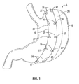
- FIG. 1 is a schematic view of a magnetic gastric reduction device wrapped around a stomach in accordance with an embodiment of the present disclosure
- FIG. 2 is a schematic view of a magnetic gastric reduction device wrapped around a stomach in accordance with another embodiment of the present disclosure
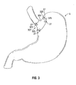
- FIG. 3 is a schematic view of a magnetic gastric reduction device wrapped around a proximal portion of a stomach in accordance with another embodiment of the present disclosure
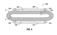
- FIG. 4 is a cross-sectional view of a magnetic gastric reduction device wrapped around a stomach in accordance with another embodiment of the present disclosure
- FIG. 5 is a schematic view of a gastric reduction control system in accordance with an embodiment of the present disclosure.
- FIG. 6 is a schematic view of a gastric reduction control system in accordance with another embodiment of the present disclosure.
- proximal will refer to the portion of the device closest to the operator and the term “distal” will refer to the portion of the device furthest from the operator.
- a flexible magnetic strip 10 is shown attached to a portion 12 of a stomach "s".
- a second flexible magnetic strip 20 (shown in phantom) is attached to an opposing side of stomach “s” that mirrors portion 12 of stomach “s”.
- the magnetic strips 10, 20 are kept in place relative to stomach “s” via suturing or other structures for fastening.
- each of the strips 10, 20 include one or more anchor holes 25 defined therethrough.
- Each anchor hole 25 is adapted to receive a suture attachment 27 (e.g., staples, tacks, sutures) therethrough for securing the strips 10, 20 to the stomach "s".
- suture attachment 27 e.g., staples, tacks, sutures
- strip 10 is magnetically attracted to strip 20, and vice-versa, such that a specific volume of the stomach may be selectively restricted or reduced, as discussed in further detail below.
- each of magnetic strips 10, 20 may be formed from a magnetic sheet material. In other embodiments, magnetic strips 10, 20 may be formed from a matrix of magnets or inductive coils.
- a flexible gastric pad 100 is shown attached to a portion 12 of stomach "s".
- a second pad 120 (shown in phantom) is attached to a corresponding portion (not shown) of stomach “s” that mirrors portion 12 of stomach “s”.
- Pads 100, 120 are kept in place relative to stomach “s” via suturing or other fastening devices (e.g., staples, tacks, sutures).
- each of the pads 100, 120 include one or more anchor holes 125 defined therethrough. Each anchor hole 125 is adapted to receive a suture attachment 27 therethrough for securing the pads 100, 120 to the stomach "s".
- pad 100 is magnetically attracted to pad 120, and vice-versa, such that a specific volume of the stomach "s” may be selectively restricted or reduced, as discussed in further detail below.
- magnetic pads 100, 120 may include a grid of magnetic elements 130, shown in phantom in the illustrated embodiment of FIG. 2 .
- Magnetic elements 130 may be any combination of permanent magnets, electromagnets, and/or magnetic sheet materials.
- Magnetic elements 130 may be magnetized electronically or electromagnetically. More specifically, each magnetic element 130 may be magnetically adjusted in either manner discussed above independently or in unison with other magnetic elements 130 to contour the stomach "s" by reducing or restricting specific portions of the stomach "s".
- a flexible band 305 is shown banded around a proximal pouch area 307 of a stomach "s".
- Band 305 is kept in place relative to proximal pouch area 307 via suturing or other fastening devices (e.g., staples, tacks, sutures).
- band 305 includes one or more anchor holes 325 defined therethrough. Each anchor hole 325 is adapted to receive a suture attachment 27 therethrough for securing the band 305 to the proximal pouch 307 of stomach "s”.
- band 305 may be, for example, a grid of electromagnets, a grid of permanent magnets, and/or a sheet of magnetic materials.
- Band 305 may be magnetized electronically or electromagnetically. In use, the band 305 is magnetized to adjust band 305 such that a specific volume of the stomach "s" may be selectively restricted or reduced, as discussed in further detail below.
- FIG. 4 shows a cross-section of a stomach "s” having a gastric reduction device 350 attached thereto.
- Gastric reduction device 350 includes a pair of magnetic reduction elements 360 and 370 disposed on opposing sides of stomach "s".
- Elements 360 and 370 may be, for example, a pair of flexible gastric strips ( FIG. 1 ), a pair of flexible gastric pads ( FIG. 2 ), or a band ( FIG. 3 ). Additionally or alternatively, elements 360, 370 may be formed as a magnetic reduction matrix ( FIGS. 5 and 6 ) that at least partially encompasses stomach "s", as will be discussed in further detail below.
- a pair of sensor layers 380 and 390 are disposed between elements 360 and 370, respectively, and an outer surface of the stomach "s".
- Sensor layers 380 and 390 are adapted to monitor pressure on the stomach, pulse oximetry, tissue oximetry, tissue vitality and/or tissue resiliency.
- sensor layers 380 and 390 may be formed as part of elements 360 and 370. Elements 360 and 370 are kept in place relative to stomach "s" via suturing. More specifically, elements 360, 370 may include one or more anchor holes (not shown) defined therethrough. Each anchor hole is adapted to receive a suture attachment 355 (e.g., staples, tacks, sutures) therethrough for securing gastric reduction device 350 and sensor layers 380, 390 to an outer surface of the stomach "s".
- a suture attachment 355 e.g., staples, tacks, sutures
- a sensor probe 375 may extend from sensor layer 380 and/or 390 through the surface of the stomach "s".
- the sensor probe 375 is adapted to sense gastric secretions inside a pocket "p" of the stomach "s".
- the pocket "p" of stomach “s” is a volume defined within the outer periphery of the stomach “s” that changes in accordance with the pressure applied by gastric reduction device 350 on stomach “s”.
- a gastric reduction control system 300 includes a magnetic reduction matrix 330 adapted to that at least partially encompass a stomach "s".
- Matrix 330 is operably coupled to an implantable control device 310.
- Implantable control device 310 is adapted to communicate with an external control device 340 to facilitate control of the magnetic reduction matrix 330 to adjust the pressure on the stomach "s" or, more specifically, restrict a specific volume of the stomach "s".
- magnetic reduction matrix 330 is embodied as a grid of magnetic elements 335.
- magnetic reduction matrix 330 may be incorporated within, for example without limitation, a flexible gastric strip ( FIG. 1 ), a flexible gastric pad ( FIG. 2 ), or a flexible band ( FIG.
- magnetic reduction matrix 330 is comprised of magnetic elements 335 in a grid-like configuration.
- Elements 335 may be, for example, electromagnets, permanent magnets, permanent magnetic sheet material, neuro-stimulating electrodes, suppression-type electrodes, or any combination thereof.
- External control device 340 is adapted to operate external to a patient and operably communicate with implantable control device 310.
- External control device 340 includes an inductive coil 342, a charge controller 344, a microcontroller 346, and an RF transmitter/receiver 348.
- External control device 340 may be coupled to a suitable power source (e.g., AC line voltage, a battery, etc.) to provide power to microcontroller 346, charge controller 344, RF transmitter/receiver 348, and inductive coil 342.
- External control device 340 is adapted to operably communicate via RF transmitter/receiver 348 with a display device 338 adapted to display sensory data, as will be discussed in further detail below.
- Implantable control device 310 is implanted within the patient and may be affixed to magnetic reduction matrix 330 or, alternatively, may be disposed within magnetic reduction matrix 330.
- Implantable control device 310 includes a battery 312, a microcontroller 314, an R.F. transmitter/receiver 316, a charging circuit 318, and an inductive coil 320.
- the microcontroller 314 and RF transmitter/receiver 316 are powered by the battery 312.
- the battery 312 is, in turn, charged by the inductive coil 320 via the charging circuit 318.
- inductive coil 342 of external control device 340 uses electrical current generated by a suitable power source to generate an electromagnetic field from which inductive coil 320 of implantable control device 310 wirelessly draws energy.
- Inductive coil 320 converts the energy drawn from inductive coil 342 back into electrical current and charging circuit 318 charges the battery 312 with the converted electrical current.
- no electrical leads or conductors from the implantable control device 310 to the external control device 340 are necessary to charge the battery 312. That is, no electrical leads or conductors from implantable control device 310 and/or magnetic reduction device 330 are external relative to the patient.
- battery 312 may be charged non-conductively from a source (i.e., external control device 340) external to the patient.
- microcontroller 314 powers microcontroller 314 and RF transmitter/receiver 316.
- the microcontroller 314 is interfaced with the magnetic reduction device 330 and various sensors associated therewith such as, for example, sensor probe 375 and sensor layers 380, 390 ( FIG. 4 ). Based on sensory feedback from the sensors and/or clinician feedback, the microcontroller 314 adjusts the magnetic reduction device 330 by magnetizing or demagnetizing any one or more magnetic elements 335 to adjust the pressure applied by the magnetic reduction device 330 on the stomach "s".
- the microcontroller 314 may alter the voltage supplied to each magnetic element 335, thereby altering the magnetic field strength of specific elements 335 and/or specific rows or sections of elements 335, which, in turn, increases or decreases the attraction between opposing elements 335, opposing rows of elements 335, and/or opposing sections of elements 335.
- Sensory data from the sensors may be transmitted from implantable control device 310 via RF transmitter/receiver 316 for subsequent storage and/or clinical review. Further, based on the transmitted sensory data, system adjustments, system status, and/or battery status may be determined.
- RF transmitter/receiver 348 of external control device 340 may be adapted to communicate with RF transmitter/receiver 316 of implantable control device 310 to receive sensory data therefrom.
- RF transmitter/receiver 348 is adapted to transmit the received sensory data to the display device 338.
- the display device 338 enables clinicians to analyze the sensory data. Further, clinicians may communicate system settings and/or software updates (i.e., via RF transmitter/receiver 348 or any suitable transmitting device) to microcontroller 314 of implantable control device 310 through RF transmitter/receiver 316.
- Sensory data received by RF transmitter/receiver 348 that is specific to the status of battery 312 may be utilized by microcontroller 346 to conduct electrical current (e.g., from a suitable power source) to inductive coil 342, as discussed herein above.
- electrical current e.g., from a suitable power source
- the amount of electrical current conducted to inductive coil 342 is controlled by charge controller 344 in accordance with the needs of battery 312 as indicated via the sensory data.
- charge controller 344 utilizing the electrical current, inductive coil 342 generates an electromagnetic field from which inductive coil 320 of implantable control device 310 wirelessly draws energy.
- microcontroller 314 of implantable control device 310 may operate in any one of various modes of operation to control the matrix 330. For example, based on sensory feedback from the sensors and/or clinician feedback, microcontroller 314 may compress a specific volume of stomach "s" when sensory feedback indicates that the patient is hungry or eating (e.g., based on sensed gastric secretions). In this scenario, microcontroller 314 may minimize the amount of time that stomach "s" is compressed or restricted to allow for the intake of food. In another scenario, if sensors or a clinician detect an illness, pregnancy, and/or consistent altered eating habits, microcontroller 314 or the clinician may terminate operation of gastric reduction control system 300 until subsequent reactivation once sufficient health of the patient is determined by the sensors or the clinician.
- system 300 may incorporate a timer to compress the stomach "s" for predetermined time periods and/or a specific time of the day.
- system 300 or, more particularly microcontroller 314, may include a voice recognition software application adapted to process voice commands from the patient and/or the clinician to selectively control the matrix 330.
- a gastric reduction control system 400 includes a magnetic reduction matrix 430 that is adapted to at least partially encompass a stomach "s".
- Matrix 430 is operably coupled to an implantable control device 410.
- Implantable control device 410 is adapted to communicate with an external control device 440 to facilitate control of the magnetic reduction matrix 430 to adjust the pressure on the stomach "s" or, more specifically, restrict a specific volume of the stomach "s".
- magnetic reduction matrix 430 is embodied as a grid of magnetic elements 460 (e.g., permanent magnets, electromagnets, etc.).
- Gastric reduction control system 400 is substantially as described above with respect to gastric reduction control system 300 of FIG. 5 and will only be described to the extent necessary to explain its difference.
- External control device 440 is adapted to operate external to a patient and operably communicate with implantable control device 410.
- External control device 440 includes a charge controller 442, a microcontroller 446, and an RF transmitter/receiver 444.
- External control device 440 may be coupled to a suitable power source (e.g., AC line voltage, a battery) to provide power to microcontroller 446, charge controller 444, and RF transmitter/receiver 448.
- External control device 440 is adapted to operably communicate via RF transmitter/receiver 444 with a display device 438 adapted to display sensory data, as will be discussed in further detail below.
- Implantable control device 410 is implanted within the patient and may be affixed to magnetic reduction matrix 430 or, alternatively, may be disposed within magnetic reduction matrix 430.
- Implantable control device 410 includes a battery 412, a microcontroller 414, an R.F. transmitter/receiver 416, and a conductive charging circuit 418.
- the conductive charging circuit 418 includes an electrical lead 420 adapted to extend from implantable control device 410 and externally from the patient. Electrical lead 420 is adapted to connect conductive charging circuit 418 to external control device 440, as will be discussed in further detail below.
- the microcontroller 414 and RF transmitter/receiver 416 are powered by the battery 412.
- the battery 412 is charged by the conductive charging circuit 418.
- the charge controller 442 regulates electrical current from the external control device 440 to the conductive charging circuit 418 based on sensory feedback from sensors (e.g., sensor probe 375, sensor layers 380, 390) and/or clinician feedback.
- Conductive charging circuit 418 conductively charges the battery 412 with the electrical current from external control device 440 and/or a suitable power source operably coupled thereto.
- battery 412 powers microcontroller 414 and RF transmitter/receiver 416.
- the microcontroller 414 is interfaced with the magnetic reduction device 330 and various sensors (e.g., sensor layers 380 and 390) associated therewith. Based on sensory feedback from the sensors and/or clinician feedback, the microcontroller 414 adjusts the magnetic reduction device 430 by magnetizing or demagnetizing any one or more magnetic elements 460 to adjust the pressure applied by magnetic reduction device 430 on the stomach "s".
- sensory data from the sensors may be transmitted from implantable control device 410 via RF transmitter/receiver 416 for subsequent storage and/or clinical review (e.g., via display 438).
- an MRI or CAT scan may be taken of the abdomen of a patient to determine geometry and/or dimensions specific to the stomach of that patient. Based on this information, custom alterations may be made to conform a magnetic reduction device to the contours of a stomach prior to implementation.
Landscapes
- Health & Medical Sciences (AREA)
- Engineering & Computer Science (AREA)
- Heart & Thoracic Surgery (AREA)
- Animal Behavior & Ethology (AREA)
- Obesity (AREA)
- Nursing (AREA)
- Orthopedic Medicine & Surgery (AREA)
- Biomedical Technology (AREA)
- Veterinary Medicine (AREA)
- Vascular Medicine (AREA)
- Life Sciences & Earth Sciences (AREA)
- Child & Adolescent Psychology (AREA)
- General Health & Medical Sciences (AREA)
- Public Health (AREA)
- Computer Networks & Wireless Communication (AREA)
- Gastroenterology & Hepatology (AREA)
- Nuclear Medicine, Radiotherapy & Molecular Imaging (AREA)
- Surgery (AREA)
- Surgical Instruments (AREA)
Applications Claiming Priority (2)
| Application Number | Priority Date | Filing Date | Title |
|---|---|---|---|
| US17515309P | 2009-05-04 | 2009-05-04 | |
| US12/758,853 US8591396B2 (en) | 2009-05-04 | 2010-04-13 | Magnetic gastric reduction device |
Publications (3)
| Publication Number | Publication Date |
|---|---|
| EP2248491A2 true EP2248491A2 (de) | 2010-11-10 |
| EP2248491A3 EP2248491A3 (de) | 2011-03-02 |
| EP2248491B1 EP2248491B1 (de) | 2016-04-06 |
Family
ID=42335176
Family Applications (1)
| Application Number | Title | Priority Date | Filing Date |
|---|---|---|---|
| EP10250862.9A Not-in-force EP2248491B1 (de) | 2009-05-04 | 2010-04-30 | Magnetische Magenverkleinerungsvorrichtung |
Country Status (2)
| Country | Link |
|---|---|
| US (1) | US8591396B2 (de) |
| EP (1) | EP2248491B1 (de) |
Cited By (1)
| Publication number | Priority date | Publication date | Assignee | Title |
|---|---|---|---|---|
| CN105030397A (zh) * | 2015-06-02 | 2015-11-11 | 朱晴 | 一种新型胃减容球囊装置 |
Families Citing this family (6)
| Publication number | Priority date | Publication date | Assignee | Title |
|---|---|---|---|---|
| US20140228627A1 (en) * | 2011-09-02 | 2014-08-14 | Edy E. Soffer | Gastric electromagnetic band controlled by automatic eating detection |
| US9962533B2 (en) * | 2013-02-14 | 2018-05-08 | William Harrison Zurn | Module for treatment of medical conditions; system for making module and methods of making module |
| EP3049034B1 (de) * | 2013-09-29 | 2017-10-25 | Institut Hospitalo-Universitaire de Chirurgie Mini -Invasive Guidee Par l'Image | Implantierbare vorrichtung zur behandlung von adipositas |
| WO2018169805A1 (en) * | 2017-03-11 | 2018-09-20 | Baronova, Inc. | Ingestible and expandable devices and assemblies for weight-loss and methods of use thereof |
| US11324512B2 (en) * | 2018-10-26 | 2022-05-10 | Torax Medical, Inc. | Magnetic sphincter augmentation device for urinary incontinence |
| CA3172308A1 (en) * | 2020-04-17 | 2021-10-21 | Michel Gagner | Magnetic devices for digestive tract partitioning |
Family Cites Families (30)
| Publication number | Priority date | Publication date | Assignee | Title |
|---|---|---|---|---|
| US7468060B2 (en) | 1998-02-19 | 2008-12-23 | Respiratory Diagnostic, Inc. | Systems and methods for treating obesity and other gastrointestinal conditions |
| US6454699B1 (en) * | 2000-02-11 | 2002-09-24 | Obtech Medical Ag | Food intake restriction with controlled wireless energy supply |
| US6558400B2 (en) | 2001-05-30 | 2003-05-06 | Satiety, Inc. | Obesity treatment tools and methods |
| US7695427B2 (en) | 2002-04-26 | 2010-04-13 | Torax Medical, Inc. | Methods and apparatus for treating body tissue sphincters and the like |
| US7175589B2 (en) | 2002-07-02 | 2007-02-13 | The Foundry Inc. | Methods and devices for luminal and sphincter augmentation |
| US7444183B2 (en) | 2003-02-03 | 2008-10-28 | Enteromedics, Inc. | Intraluminal electrode apparatus and method |
| CN1838978B (zh) | 2003-06-20 | 2010-05-26 | 超治疗股份有限公司 | 用于治疗疾病的胃肠方法和装置 |
| US20040267291A1 (en) | 2003-06-27 | 2004-12-30 | Byrum Randal T. | Implantable band with non-mechanical attachment mechanism |
| CN1856338B (zh) | 2003-07-21 | 2012-11-14 | 超治疗有限公司 | 用于治疗疾病和控制血糖的胃肠方法和装置 |
| US20050247320A1 (en) | 2003-10-10 | 2005-11-10 | Stack Richard S | Devices and methods for retaining a gastro-esophageal implant |
| US7758493B2 (en) | 2003-10-23 | 2010-07-20 | Proxy Biomedical Limited | Gastric constriction device |
| US20080300618A1 (en) | 2004-03-23 | 2008-12-04 | Michael Eric Gertner | Obesity treatment systems |
| WO2006049725A2 (en) * | 2004-03-23 | 2006-05-11 | Minimus Surgical Systems | Surgical systems and devices to enhance gastric restriction therapies |
| ITRE20050009A1 (it) | 2005-02-10 | 2006-08-11 | Mauro Bortolotti | Dispositivo medico antireflusso basato sull'azione di magneti |
| US8251888B2 (en) * | 2005-04-13 | 2012-08-28 | Mitchell Steven Roslin | Artificial gastric valve |
| US7899540B2 (en) * | 2005-04-29 | 2011-03-01 | Cyberonics, Inc. | Noninvasively adjustable gastric band |
| US7835796B2 (en) | 2005-04-29 | 2010-11-16 | Cyberonics, Inc. | Weight loss method and device |
| WO2008005387A2 (en) | 2006-06-30 | 2008-01-10 | Cvdevices, Llc | Magnetic devices for organ remodeling |
| US8147506B2 (en) | 2005-08-05 | 2012-04-03 | Ethicon Endo-Surgery, Inc. | Method and clamp for gastric reduction surgery |
| US8123768B2 (en) | 2005-10-24 | 2012-02-28 | Gil Vardi | Method and system to restrict stomach size |
| US20070265646A1 (en) | 2006-01-17 | 2007-11-15 | Ellipse Technologies, Inc. | Dynamically adjustable gastric implants |
| US20070239179A1 (en) | 2006-03-31 | 2007-10-11 | Ethicon Endo-Surgery, Inc. | Compliant Gastroplasty: Devices And Methods |
| US20070293878A1 (en) | 2006-06-16 | 2007-12-20 | Butsch John L | Magnetic mesh support for tissue walls |
| US20080172072A1 (en) | 2007-01-11 | 2008-07-17 | Ellipse Technologies, Inc. | Internal sensors for use with gastric restriction devices |
| US8721718B2 (en) | 2007-01-23 | 2014-05-13 | Cvdevices, Llc | Systems and methods for valve annulus remodeling |
| WO2008150905A1 (en) | 2007-05-29 | 2008-12-11 | Kassab Ghassan S | Devices, systems, and methods for achieving gastric bypass |
| US8167896B2 (en) | 2007-05-29 | 2012-05-01 | Cvdevices, Llc | Devices, systems, and methods for organ restriction |
| US8214049B2 (en) * | 2007-07-25 | 2012-07-03 | Intrapace Inc. | Gastric stimulation systems and methods utilizing a transgastric probe |
| US20090275961A1 (en) | 2008-05-01 | 2009-11-05 | Harris Jason L | Gastric volume reduction using anterior to posterior wall junctions |
| US8137260B2 (en) * | 2008-05-22 | 2012-03-20 | Edwards Lifesciences Corporation | Electromagnetic cardiac assist device and method |
-
2010
- 2010-04-13 US US12/758,853 patent/US8591396B2/en not_active Expired - Fee Related
- 2010-04-30 EP EP10250862.9A patent/EP2248491B1/de not_active Not-in-force
Non-Patent Citations (1)
| Title |
|---|
| None |
Cited By (1)
| Publication number | Priority date | Publication date | Assignee | Title |
|---|---|---|---|---|
| CN105030397A (zh) * | 2015-06-02 | 2015-11-11 | 朱晴 | 一种新型胃减容球囊装置 |
Also Published As
| Publication number | Publication date |
|---|---|
| US20100280304A1 (en) | 2010-11-04 |
| US8591396B2 (en) | 2013-11-26 |
| EP2248491B1 (de) | 2016-04-06 |
| EP2248491A3 (de) | 2011-03-02 |
Similar Documents
| Publication | Publication Date | Title |
|---|---|---|
| US8591396B2 (en) | Magnetic gastric reduction device | |
| JP4902260B2 (ja) | 磁気共鳴映像法(mri)に対して安全な遠隔で調節可能な人工的括約筋 | |
| US8862241B2 (en) | System for supplying energy to an implantable medical device | |
| US10881869B2 (en) | Wireless re-charge of an implantable medical device | |
| EP1554998B1 (de) | Medizinische Vorrichtung zur Begrenzung der Nahrungsaufnahme | |
| CN109996585B (zh) | 具有导磁壳体和围绕该壳体设置的感应线圈的植入式医疗设备 | |
| US11247049B2 (en) | Wireless tissue stimulation devices | |
| US20120123498A1 (en) | Sleep apnea treatment system | |
| US20120053657A1 (en) | Implant recharging | |
| MXPA03010602A (es) | Aparato para el tratamiento de enfermedades de reflujo y pirosis. | |
| US20110295337A1 (en) | Systems and Methods For Regulating Metabolic Hormone Producing Tissue | |
| US20150148861A1 (en) | Sleep apnea treatment | |
| US10576276B2 (en) | Implanted magnet management in the face of external magnetic fields | |
| WO2007121265A1 (en) | Apparatus and method utilizing magnetic field | |
| JP2004073725A (ja) | 経皮的エネルギ移送装置 | |
| WO2025008686A1 (en) | System and method for direct retention force measurement | |
| AU2024304552A1 (en) | Implantable medical device with tethered power and communication interface | |
| Deb | Miniature wireless gastrostimulator | |
| HK1098038A (en) | Remotely adjustable artificial sphincter |
Legal Events
| Date | Code | Title | Description |
|---|---|---|---|
| PUAI | Public reference made under article 153(3) epc to a published international application that has entered the european phase |
Free format text: ORIGINAL CODE: 0009012 |
|
| AK | Designated contracting states |
Kind code of ref document: A2 Designated state(s): AT BE BG CH CY CZ DE DK EE ES FI FR GB GR HR HU IE IS IT LI LT LU LV MC MK MT NL NO PL PT RO SE SI SK SM TR |
|
| AX | Request for extension of the european patent |
Extension state: AL BA ME RS |
|
| PUAL | Search report despatched |
Free format text: ORIGINAL CODE: 0009013 |
|
| AK | Designated contracting states |
Kind code of ref document: A3 Designated state(s): AT BE BG CH CY CZ DE DK EE ES FI FR GB GR HR HU IE IS IT LI LT LU LV MC MK MT NL NO PL PT RO SE SI SK SM TR |
|
| AX | Request for extension of the european patent |
Extension state: AL BA ME RS |
|
| 17P | Request for examination filed |
Effective date: 20110901 |
|
| 17Q | First examination report despatched |
Effective date: 20120424 |
|
| RAP1 | Party data changed (applicant data changed or rights of an application transferred) |
Owner name: COVIDIEN LP |
|
| GRAP | Despatch of communication of intention to grant a patent |
Free format text: ORIGINAL CODE: EPIDOSNIGR1 |
|
| INTG | Intention to grant announced |
Effective date: 20151013 |
|
| GRAS | Grant fee paid |
Free format text: ORIGINAL CODE: EPIDOSNIGR3 |
|
| GRAA | (expected) grant |
Free format text: ORIGINAL CODE: 0009210 |
|
| AK | Designated contracting states |
Kind code of ref document: B1 Designated state(s): AT BE BG CH CY CZ DE DK EE ES FI FR GB GR HR HU IE IS IT LI LT LU LV MC MK MT NL NO PL PT RO SE SI SK SM TR |
|
| REG | Reference to a national code |
Ref country code: GB Ref legal event code: FG4D |
|
| REG | Reference to a national code |
Ref country code: AT Ref legal event code: REF Ref document number: 786905 Country of ref document: AT Kind code of ref document: T Effective date: 20160415 Ref country code: CH Ref legal event code: EP |
|
| REG | Reference to a national code |
Ref country code: IE Ref legal event code: FG4D |
|
| REG | Reference to a national code |
Ref country code: DE Ref legal event code: R096 Ref document number: 602010032015 Country of ref document: DE |
|
| REG | Reference to a national code |
Ref country code: FR Ref legal event code: PLFP Year of fee payment: 7 |
|
| REG | Reference to a national code |
Ref country code: LT Ref legal event code: MG4D Ref country code: NL Ref legal event code: MP Effective date: 20160406 |
|
| REG | Reference to a national code |
Ref country code: AT Ref legal event code: MK05 Ref document number: 786905 Country of ref document: AT Kind code of ref document: T Effective date: 20160406 |
|
| PG25 | Lapsed in a contracting state [announced via postgrant information from national office to epo] |
Ref country code: BE Free format text: LAPSE BECAUSE OF NON-PAYMENT OF DUE FEES Effective date: 20160430 |
|
| PG25 | Lapsed in a contracting state [announced via postgrant information from national office to epo] |
Ref country code: NL Free format text: LAPSE BECAUSE OF FAILURE TO SUBMIT A TRANSLATION OF THE DESCRIPTION OR TO PAY THE FEE WITHIN THE PRESCRIBED TIME-LIMIT Effective date: 20160406 |
|
| PG25 | Lapsed in a contracting state [announced via postgrant information from national office to epo] |
Ref country code: LT Free format text: LAPSE BECAUSE OF FAILURE TO SUBMIT A TRANSLATION OF THE DESCRIPTION OR TO PAY THE FEE WITHIN THE PRESCRIBED TIME-LIMIT Effective date: 20160406 Ref country code: FI Free format text: LAPSE BECAUSE OF FAILURE TO SUBMIT A TRANSLATION OF THE DESCRIPTION OR TO PAY THE FEE WITHIN THE PRESCRIBED TIME-LIMIT Effective date: 20160406 Ref country code: IS Free format text: LAPSE BECAUSE OF FAILURE TO SUBMIT A TRANSLATION OF THE DESCRIPTION OR TO PAY THE FEE WITHIN THE PRESCRIBED TIME-LIMIT Effective date: 20160806 Ref country code: NO Free format text: LAPSE BECAUSE OF FAILURE TO SUBMIT A TRANSLATION OF THE DESCRIPTION OR TO PAY THE FEE WITHIN THE PRESCRIBED TIME-LIMIT Effective date: 20160706 Ref country code: PL Free format text: LAPSE BECAUSE OF FAILURE TO SUBMIT A TRANSLATION OF THE DESCRIPTION OR TO PAY THE FEE WITHIN THE PRESCRIBED TIME-LIMIT Effective date: 20160406 |
|
| PG25 | Lapsed in a contracting state [announced via postgrant information from national office to epo] |
Ref country code: ES Free format text: LAPSE BECAUSE OF FAILURE TO SUBMIT A TRANSLATION OF THE DESCRIPTION OR TO PAY THE FEE WITHIN THE PRESCRIBED TIME-LIMIT Effective date: 20160406 Ref country code: SE Free format text: LAPSE BECAUSE OF FAILURE TO SUBMIT A TRANSLATION OF THE DESCRIPTION OR TO PAY THE FEE WITHIN THE PRESCRIBED TIME-LIMIT Effective date: 20160406 Ref country code: PT Free format text: LAPSE BECAUSE OF FAILURE TO SUBMIT A TRANSLATION OF THE DESCRIPTION OR TO PAY THE FEE WITHIN THE PRESCRIBED TIME-LIMIT Effective date: 20160808 Ref country code: AT Free format text: LAPSE BECAUSE OF FAILURE TO SUBMIT A TRANSLATION OF THE DESCRIPTION OR TO PAY THE FEE WITHIN THE PRESCRIBED TIME-LIMIT Effective date: 20160406 Ref country code: GR Free format text: LAPSE BECAUSE OF FAILURE TO SUBMIT A TRANSLATION OF THE DESCRIPTION OR TO PAY THE FEE WITHIN THE PRESCRIBED TIME-LIMIT Effective date: 20160707 Ref country code: HR Free format text: LAPSE BECAUSE OF FAILURE TO SUBMIT A TRANSLATION OF THE DESCRIPTION OR TO PAY THE FEE WITHIN THE PRESCRIBED TIME-LIMIT Effective date: 20160406 Ref country code: LV Free format text: LAPSE BECAUSE OF FAILURE TO SUBMIT A TRANSLATION OF THE DESCRIPTION OR TO PAY THE FEE WITHIN THE PRESCRIBED TIME-LIMIT Effective date: 20160406 |
|
| REG | Reference to a national code |
Ref country code: CH Ref legal event code: PL |
|
| PG25 | Lapsed in a contracting state [announced via postgrant information from national office to epo] |
Ref country code: BE Free format text: LAPSE BECAUSE OF FAILURE TO SUBMIT A TRANSLATION OF THE DESCRIPTION OR TO PAY THE FEE WITHIN THE PRESCRIBED TIME-LIMIT Effective date: 20160406 Ref country code: IT Free format text: LAPSE BECAUSE OF FAILURE TO SUBMIT A TRANSLATION OF THE DESCRIPTION OR TO PAY THE FEE WITHIN THE PRESCRIBED TIME-LIMIT Effective date: 20160406 |
|
| REG | Reference to a national code |
Ref country code: DE Ref legal event code: R097 Ref document number: 602010032015 Country of ref document: DE |
|
| PG25 | Lapsed in a contracting state [announced via postgrant information from national office to epo] |
Ref country code: RO Free format text: LAPSE BECAUSE OF FAILURE TO SUBMIT A TRANSLATION OF THE DESCRIPTION OR TO PAY THE FEE WITHIN THE PRESCRIBED TIME-LIMIT Effective date: 20160406 Ref country code: CZ Free format text: LAPSE BECAUSE OF FAILURE TO SUBMIT A TRANSLATION OF THE DESCRIPTION OR TO PAY THE FEE WITHIN THE PRESCRIBED TIME-LIMIT Effective date: 20160406 Ref country code: EE Free format text: LAPSE BECAUSE OF FAILURE TO SUBMIT A TRANSLATION OF THE DESCRIPTION OR TO PAY THE FEE WITHIN THE PRESCRIBED TIME-LIMIT Effective date: 20160406 Ref country code: DK Free format text: LAPSE BECAUSE OF FAILURE TO SUBMIT A TRANSLATION OF THE DESCRIPTION OR TO PAY THE FEE WITHIN THE PRESCRIBED TIME-LIMIT Effective date: 20160406 Ref country code: SK Free format text: LAPSE BECAUSE OF FAILURE TO SUBMIT A TRANSLATION OF THE DESCRIPTION OR TO PAY THE FEE WITHIN THE PRESCRIBED TIME-LIMIT Effective date: 20160406 Ref country code: LI Free format text: LAPSE BECAUSE OF NON-PAYMENT OF DUE FEES Effective date: 20160430 Ref country code: CH Free format text: LAPSE BECAUSE OF NON-PAYMENT OF DUE FEES Effective date: 20160430 Ref country code: MC Free format text: LAPSE BECAUSE OF FAILURE TO SUBMIT A TRANSLATION OF THE DESCRIPTION OR TO PAY THE FEE WITHIN THE PRESCRIBED TIME-LIMIT Effective date: 20160406 |
|
| PLBE | No opposition filed within time limit |
Free format text: ORIGINAL CODE: 0009261 |
|
| STAA | Information on the status of an ep patent application or granted ep patent |
Free format text: STATUS: NO OPPOSITION FILED WITHIN TIME LIMIT |
|
| PG25 | Lapsed in a contracting state [announced via postgrant information from national office to epo] |
Ref country code: SM Free format text: LAPSE BECAUSE OF FAILURE TO SUBMIT A TRANSLATION OF THE DESCRIPTION OR TO PAY THE FEE WITHIN THE PRESCRIBED TIME-LIMIT Effective date: 20160406 |
|
| 26N | No opposition filed |
Effective date: 20170110 |
|
| REG | Reference to a national code |
Ref country code: FR Ref legal event code: PLFP Year of fee payment: 8 |
|
| PG25 | Lapsed in a contracting state [announced via postgrant information from national office to epo] |
Ref country code: SI Free format text: LAPSE BECAUSE OF FAILURE TO SUBMIT A TRANSLATION OF THE DESCRIPTION OR TO PAY THE FEE WITHIN THE PRESCRIBED TIME-LIMIT Effective date: 20160406 |
|
| REG | Reference to a national code |
Ref country code: FR Ref legal event code: PLFP Year of fee payment: 9 |
|
| PG25 | Lapsed in a contracting state [announced via postgrant information from national office to epo] |
Ref country code: CY Free format text: LAPSE BECAUSE OF FAILURE TO SUBMIT A TRANSLATION OF THE DESCRIPTION OR TO PAY THE FEE WITHIN THE PRESCRIBED TIME-LIMIT Effective date: 20160406 Ref country code: HU Free format text: LAPSE BECAUSE OF FAILURE TO SUBMIT A TRANSLATION OF THE DESCRIPTION OR TO PAY THE FEE WITHIN THE PRESCRIBED TIME-LIMIT; INVALID AB INITIO Effective date: 20100430 |
|
| PG25 | Lapsed in a contracting state [announced via postgrant information from national office to epo] |
Ref country code: TR Free format text: LAPSE BECAUSE OF FAILURE TO SUBMIT A TRANSLATION OF THE DESCRIPTION OR TO PAY THE FEE WITHIN THE PRESCRIBED TIME-LIMIT Effective date: 20160406 Ref country code: MK Free format text: LAPSE BECAUSE OF FAILURE TO SUBMIT A TRANSLATION OF THE DESCRIPTION OR TO PAY THE FEE WITHIN THE PRESCRIBED TIME-LIMIT Effective date: 20160406 Ref country code: MT Free format text: LAPSE BECAUSE OF NON-PAYMENT OF DUE FEES Effective date: 20160430 Ref country code: LU Free format text: LAPSE BECAUSE OF NON-PAYMENT OF DUE FEES Effective date: 20160430 |
|
| PG25 | Lapsed in a contracting state [announced via postgrant information from national office to epo] |
Ref country code: BG Free format text: LAPSE BECAUSE OF FAILURE TO SUBMIT A TRANSLATION OF THE DESCRIPTION OR TO PAY THE FEE WITHIN THE PRESCRIBED TIME-LIMIT Effective date: 20160406 |
|
| PGFP | Annual fee paid to national office [announced via postgrant information from national office to epo] |
Ref country code: GB Payment date: 20200323 Year of fee payment: 11 Ref country code: IE Payment date: 20200318 Year of fee payment: 11 |
|
| GBPC | Gb: european patent ceased through non-payment of renewal fee |
Effective date: 20210430 |
|
| PG25 | Lapsed in a contracting state [announced via postgrant information from national office to epo] |
Ref country code: GB Free format text: LAPSE BECAUSE OF NON-PAYMENT OF DUE FEES Effective date: 20210430 |
|
| PG25 | Lapsed in a contracting state [announced via postgrant information from national office to epo] |
Ref country code: IE Free format text: LAPSE BECAUSE OF NON-PAYMENT OF DUE FEES Effective date: 20210430 |
|
| PGFP | Annual fee paid to national office [announced via postgrant information from national office to epo] |
Ref country code: FR Payment date: 20230321 Year of fee payment: 14 |
|
| PGFP | Annual fee paid to national office [announced via postgrant information from national office to epo] |
Ref country code: DE Payment date: 20230321 Year of fee payment: 14 |
|
| REG | Reference to a national code |
Ref country code: DE Ref legal event code: R119 Ref document number: 602010032015 Country of ref document: DE |
|
| PG25 | Lapsed in a contracting state [announced via postgrant information from national office to epo] |
Ref country code: DE Free format text: LAPSE BECAUSE OF NON-PAYMENT OF DUE FEES Effective date: 20241105 |
|
| PG25 | Lapsed in a contracting state [announced via postgrant information from national office to epo] |
Ref country code: FR Free format text: LAPSE BECAUSE OF NON-PAYMENT OF DUE FEES Effective date: 20240430 |
|
| PG25 | Lapsed in a contracting state [announced via postgrant information from national office to epo] |
Ref country code: FR Free format text: LAPSE BECAUSE OF NON-PAYMENT OF DUE FEES Effective date: 20240430 Ref country code: DE Free format text: LAPSE BECAUSE OF NON-PAYMENT OF DUE FEES Effective date: 20241105 |