EP2248498B1 - Frein électrique dynamique pour articles mobiles - Google Patents
Frein électrique dynamique pour articles mobiles Download PDFInfo
- Publication number
- EP2248498B1 EP2248498B1 EP10250563.3A EP10250563A EP2248498B1 EP 2248498 B1 EP2248498 B1 EP 2248498B1 EP 10250563 A EP10250563 A EP 10250563A EP 2248498 B1 EP2248498 B1 EP 2248498B1
- Authority
- EP
- European Patent Office
- Prior art keywords
- brake command
- generator
- controller
- brake
- bed
- Prior art date
- Legal status (The legal status is an assumption and is not a legal conclusion. Google has not performed a legal analysis and makes no representation as to the accuracy of the status listed.)
- Active
Links
- 238000006073 displacement reaction Methods 0.000 claims description 8
- 238000005096 rolling process Methods 0.000 claims description 8
- 239000012636 effector Substances 0.000 description 14
- 238000010586 diagram Methods 0.000 description 10
- XDTMQSROBMDMFD-UHFFFAOYSA-N C1CCCCC1 Chemical compound C1CCCCC1 XDTMQSROBMDMFD-UHFFFAOYSA-N 0.000 description 2
- 230000003068 static effect Effects 0.000 description 2
- 230000003247 decreasing effect Effects 0.000 description 1
- 230000003292 diminished effect Effects 0.000 description 1
- 230000000694 effects Effects 0.000 description 1
- 230000003100 immobilizing effect Effects 0.000 description 1
- 238000012544 monitoring process Methods 0.000 description 1
- 238000004804 winding Methods 0.000 description 1
Images






Classifications
-
- A—HUMAN NECESSITIES
- A61—MEDICAL OR VETERINARY SCIENCE; HYGIENE
- A61G—TRANSPORT, PERSONAL CONVEYANCES, OR ACCOMMODATION SPECIALLY ADAPTED FOR PATIENTS OR DISABLED PERSONS; OPERATING TABLES OR CHAIRS; CHAIRS FOR DENTISTRY; FUNERAL DEVICES
- A61G7/00—Beds specially adapted for nursing; Devices for lifting patients or disabled persons
- A61G7/05—Parts, details or accessories of beds
-
- A—HUMAN NECESSITIES
- A61—MEDICAL OR VETERINARY SCIENCE; HYGIENE
- A61G—TRANSPORT, PERSONAL CONVEYANCES, OR ACCOMMODATION SPECIALLY ADAPTED FOR PATIENTS OR DISABLED PERSONS; OPERATING TABLES OR CHAIRS; CHAIRS FOR DENTISTRY; FUNERAL DEVICES
- A61G7/00—Beds specially adapted for nursing; Devices for lifting patients or disabled persons
- A61G7/05—Parts, details or accessories of beds
- A61G7/0528—Steering or braking devices for castor wheels
Definitions
- the subject matter described herein relates to movable articles such as hospital beds and particularly to a movable article having a dynamic electric brake for decelerating the article.
- Occupant supports such as hospital beds are frequently outfitted with wheels or casters to make the bed mobile. Although some beds may be equipped with a propulsion unit, many beds must be moved manually. Because hospital beds are heavy it may not be possible for the person moving the bed to stop it quickly, for example to avoid a pedestrian. Hospital beds are often equipped with static brakes, but such brakes are not intended to decelerate a moving bed. Instead, they are merely latches for immobilizing the casters when the bed is stationary and intended to remain stationary. Moreover, static brakes are conventionally operated by foot pedals not intended to be operated by a person moving the bed.
- US 2003/0102172 discloses a patient support including a propulsion device for moving the patient support.
- An automatic braking system is provided to selectively brake the patient support.
- the support has a driver wheel and the motor which drives the wheel is used to provide the automatic braking system by shorting the power leads to it.
- the invention provides a patient support comprising a frame, at least one rolling element upon which the frame can be rolled from an origin to a destination, a brake command generator adapted to generate a brake command for decelerating the patient support
- a brake command generator adapted to generate a brake command for decelerating the patient support
- an electromachine capable of producing an output in response to the brake command for decelerating the rolling element
- the electromachine is a generator having a rotary input whose source is rotary motion of the rolling element
- the support include a controller in communication with the brake command generator, and wherein the rotary input is capable of being decelerated by an electrical load applied to the generator, characterised in that the patient support Is a hospital bed and in that the controller establishes the electrical load at a value commensurate with the magnitude of the brake command.
- FIG. 1 is a schematic, side elevation view of a hospital bed.
- FIG. 2 is an enlarged view of a variant of a handgrip portion of the bed of FIG. 1 .
- FIG. 3 is an enlarged view of another variant of the handgrip portion of the bed of FIG. 1 .
- FIG. 4 is a block diagram depicting a basic configuration of a dynamic electric braking system for the bed of FIG. 1 .
- FIG. 5 is a block diagram similar to FIG. 4 showing the braking system enhanced by the presence of a battery and a controller.
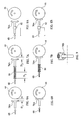
- FIGS. 6A & 6B are schematic views of a braking effector in the form of a brake shoe.
- FIGS. 7A & 7B are schematic views of a braking effector in the form of a brake shoe and also showing a spring mediating between the brake shoe and the output of a motor.
- FIGS. 8A & 8B are schematic views showing a braking effector in the form of a brake shoe and also showing a load cell for determining braking force.
- FIG. 9 is a schematic view of a braking effector in the form of a caliper.
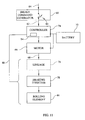
- FIG. 10 is a view similar to FIG. 5 in which a brake command generator is represented as a simple electrical switch.
- FIG. 11 is a view similar to FIG. 10 showing a feedback path extending between a controller and a component mechanically downstream of a motor.
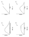
- FIGS. 12 - 15 are deceleration schedules described in the context of FIG. 11 but also useable in other configurations of a dynamic braking system.
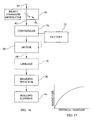
- FIG. 16 is a block diagram depicting a braking system in which a brake command generator produces a non-discrete brake command.
- FIG. 17 is a sample relationship between physical position of a brake actuator and the magnitude of a braking force or the magnitude of a braking request received by a controller.
- FIG. 18 is a block diagram depicting a braking system using an electrical generator.
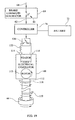
- FIG. 19 is a block diagram similar to FIG. 18 in which a brake command generator is represented as a simple electrical switch which may be included as part of the handgrip of FIG. 2 .
- FIG. 20 is a block diagram similar to FIG. 18 in which a controller includes a predefined, open loop deceleration schedule of electrical load as a function of time.
- FIG. 21 is a sample schedule of electrical load as a function of time described in the context of FIG. 20 but also useable in other configurations of a dynamic braking system.
- FIG. 22 is a block diagram similar to FIG. 20 but also including a feedback path 88 to a controller to allow closed loop control of bed deceleration.
- FIG. 23 depicts a sample control schedule of resistive load as a function of bed speed or deceleration described in the context of FIG. 22 but also useable in other configurations of a dynamic braking system.
- FIG. 24 is a block diagram similar to FIG. 22 showing a feedback path extending from the generator to the controller.
- FIG. 25 is a deceleration schedule of resistive load as a function of generator output voltage described in the context of FIG. 24 but also useable in other configurations of a dynamic braking system.
- FIG. 26 is a block diagram describing a pulse width modulated braking system according to the invention in which a brake command generator produces a non-discrete brake command.
- FIG. 27 is a schedule of pulse width modulation duty cycle as a function of physical position of the brake actuator described in the context of FIG. 26 .
- FIG. 28 is a block diagram similar to FIG. 20 depicting another braking system according to the invention in which the output of a brake command generator is a non-discrete output.
- FIG. 29 is a sample relationship between physical position of a brake actuator such as the handgrip trigger of FIG. 2 or the lever of FIG. 3 and the magnitude of a brake command.
- an occupant support represented by hospital bed 30 includes a frame 32, a mattress 34, a headboard 36, a footboard 38 and siderails 40.
- Rolling elements such as wheels or a set of casters 44, one near each corner of the frame, impart mobility to the frame, and therefore to the bed as a whole, allowing a person to roll the bed from an origin to a destination.
- a handle 46 extends from the frame to a handgrip 48.
- the handgrip may be of any suitable configuration.
- One example is the loop handgrip of FIG. 2 .
- the loop handgrip includes a trigger 50 which, when squeezed by a human operator, recedes partly into the handgrip.
- the handlebar handgrip includes a lever 52 mounted on the handle and rotatable about axis 54 when squeezed by a human operator. When the operator releases the lever it returns to its original position under the influence of a spring, not shown.
- the handlebar handgrip includes a lever 52 mounted on the handle and rotatable about axis 54 when squeezed by a human operator. When the operator releases the lever it returns to its original position under the influence of a spring, not shown
- Features such as the trigger and lever may be referred to herein collectively as an actuator.
- FIG. 4 shows the basic configuration of a dynamic electric braking system.
- the braking system includes a brake command generator 60 for generating a brake command 62 in response to an operator input 64 .
- the command generator includes the actuator 50, 52. Movement of the actuator signifies the operator's intention to decelerate a moving bed.
- the braking system also includes an electromachine 66, for example an electric motor or electric generator capable of producing an output 68 responsive to the brake command for decelerating the rolling element 44.
- FIG. 5 shows a version of the system of FIG. 4 enhanced by the presence of a battery 72 and a controller 74 (e.g. a microprocessor powered by the battery) in communication with the brake command generator and the electromachine.
- FIG. 5 also shows the electromachine as a motor 66 powered by the battery.
- FIG. 5 also shows the output 68 of the motor acting on a linkage 76 which, in turn, acts on a braking effector 78.
- the motor output 68 may act directly on the braking effector.
- the braking effector may take on any suitable form, for example a brake shoe 78A that contacts a brake drum or the casters themselves ( FIGS.
- Brake linings may be applied to one or both of the contacting components if desired. Irrespective of the form of the braking effector, it is responsive, directly or indirectly, to the output of the electromachine to effect the desired deceleration of the bed.
- the braking effector may operate on only one of the four casters typically found on hospital beds, or there may be more than one effector, each dedicated to one caster.
- an operator activates the brake command generator 60, for example by squeezing the trigger of FIG. 2 or the lever of FIG. 3 , thereby issuing a brake command 62 to operate the motor.
- the rotation of the motor shaft moves the linkage, if present, or moves the braking effector directly to cause the braking effector to decelerate the casters, and therefore the bed as a whole.
- the operator may decelerate the bed to a complete stop or merely bring it to a slower speed.
- FIG. 10 shows a simple arrangement in which the brake command generator 60 is represented as a simple electrical switch 84 which may be included as part of the handgrip. Because the switch has only two states, open and closed, the output of the brake command generator is a discrete brake command. The switch is normally open. An operator closes the switch by way of the actuator. This signals the controller to supply power to the motor to operate the braking effector as already described.
- FIGS. 6A and 6B there is a fixed kinematic relationship between the motor output and the response of the braking effector as represented by brake shoe 78A. Specifically, the system moves the brake shoe a fixed distance D1 in response to the motor output. Such an arrangement is mechanically simple but will result in diminished braking force as a result of shoe and or drum wear.
- a spring 86 or other purposefully elastic element mediates between the motor output 68 and the brake shoe. The motor causes a displacement D2 at the input side of the spring which results in a displacement D3 of the brake shoe.
- FIG. 11 shows an arrangement similar to that of FIG. 10 but with a feedback path 88 extending from one of the components mechanically downstream of the motor to the controller.
- a system may include a load cell 92 to monitor the force applied to the drum by shoe 78A. The magnitude of the force is fed back to the controller by way of the feedback path 88.
- the controller includes a predefined deceleration schedule 94 which schedules or governs the deceleration, typically as a function of an independent variable. Such a schedule may simply specify a constant force, in which case the controller causes the motor to continually adjust the displacement of the brake shoe to achieve the scheduled constant braking force. As seen in FIG.
- FIGS. 13 - 15 show, by way of example only, linear, piecewise linear and nonlinear time-based deceleration schedules.
- FIG. 16 illustrates an arrangement in which the brake command generator produces a non-discrete brake command.
- the arrangement includes a variable resistor 96 responsive to the physical position of the actuator.
- the physical position of the actuator governs the resistance of the variable resistor, which is reflected in the brake command 62 issued to the controller.
- the system will be configured so that increased displacement of the actuator results in increased braking force.
- FIG. 17 shows a sample relationship between physical position of the trigger or lever and the magnitude of the braking force. Alternatively, FIG. 17 can be interpreted as the magnitude of the request received by the controller. The relationship may be linear or nonlinear.
- FIG. 18 shows an arrangement in which the electromachine is a generator 66 having a rotatable input shaft 112 connected to or integral with generator rotor 113.
- the arrangement also includes a variable resistance 116 connected across the terminals.
- the controller 74 regulates the magnitude of the resistance 116 in response to a command issued by the brake command generator 60. When braking is not requested the controller opens the circuit between terminals 114. As a result, no current flows in the circuit, and so the generator offers no mechanical resistance to rotation of the casters.
- the controller sets resistance 116 to a value commensurate with the magnitude of the brake command 62.
- a low electrical resistance allows a high current in the stator windings, which strongly resists rotation of the rotor; a higher electrical resistance reduces current flow in the stator, thereby decreasing the electromechanical resistance to rotation of the rotor and allowing the casters to roll more freely.
- the electrical resistance causes the generator to produce an output in the form of a resistive torque 118 that counteracts the input torque 119 delivered to the generator by the casters, thereby decelerating the bed.
- the controller governs the speed of the rotary input by applying a resistive electrical load to the electrical generator 66.
- the electrical generator could power the controller by way of electrical connection 122, however the controller would receive power only while the bed was in motion.
- a battery 72 is used if it is desired to continuously power the controller.
- the generator may be connected to the battery by a connection 124 so that the generator can be used to charge the battery.
- FIG. 19 shows an arrangement similar to that of FIG. 18 in which the brake command generator 60 is represented as a simple electrical switch 84 which may be included as part of the handgrip 48 ( FIGS. 1-3 ). Because the switch has only two states, open and closed, the output of the brake command generator is a discrete brake command.
- the switch is normally open. An operator closes the switch by way of the trigger 50, lever 52 or other actuator. This signals the controller to apply an appropriate pre-selected resistance 122 across the generator terminals. In the illustrated embodiment the controller closes a second switch 126 to apply the resistance.
- FIG. 20 shows an arrangement similar to that of FIG. 18 in which the controller includes a predefined, open loop deceleration schedule of electrical load as a function of time, such as the schedule of FIG. 21 .
- the controller receives a brake command 62 it varies the resistance of variable resistor 116 according to the schedule to decelerate the bed.
- FIG. 22 shows an arrangement similar to that of FIG. 20 but also including a feedback path 88 to the controller to allow closed loop control of bed deceleration.
- the controller includes a control schedule 94 such as the schedule of FIG. 23 which schedules the resistive load as a function of bed speed or deceleration.
- Bed speed may be determined by, for example, monitoring the rotational speed of the casters as suggested by the origin of feedback path 88 in FIG. 22 .
- Bed speed may alternatively be determined by integrating the output of an accelerometer affixed to the bed frame.
- FIG. 24 shows a similar arrangement in which the feedback path 88 extends from the generator to the controller, and the deceleration schedule ( FIG. 25 ) is a schedule of resistive load as a function of generator output voltage, which is a function of speed.
- FIG. 26 illustrates a pulse width modulated (PWM) arrangement in which the brake command generator 60 produces a non-discrete brake command 62.
- the arrangement includes a variable resistor 96 responsive to the physical position of the handgrip trigger 50 or lever 52.
- the physical position of the trigger or lever governs the resistance of the variable resistor, which is reflected in the brake command 62 issued to the controller.
- the terminals 114 of the electrical generator 66 are connected to a fixed value resistor 122 in series with a switch 126.
- the controller includes a schedule 94 of pulse width modulation duty cycle ( FIG. 27 ) as a function of physical position of the trigger 50 or lever 52.
- the switch 126 closes and opens in a pattern that mimics the PWM cycle. As the duty cycle increases, the switch 126 remains closed for a larger proportion of time, thereby causing the generator to experience a time averaged resistance lower than the resistance associated with an open circuit (switch 126 open) and therefore to decelerate the bed more quickly.
- FIG. 28 shows an arrangement similar to that of FIG. 20 except that output 62 of the brake command generator is non-discrete, similar to the non-discrete commands already described in the context of FIGS. 16 and 26 .
- the controller receives the variable braking command and, in accordance with the magnitude of the command, sets the resistance of the variable resistor 116.
- FIG. 29 shows an example of a relationship between physical position of the handgrip trigger or lever and the magnitude of the brake command 62.
Landscapes
- Health & Medical Sciences (AREA)
- Nursing (AREA)
- Life Sciences & Earth Sciences (AREA)
- Animal Behavior & Ethology (AREA)
- General Health & Medical Sciences (AREA)
- Public Health (AREA)
- Veterinary Medicine (AREA)
- Invalid Beds And Related Equipment (AREA)
- Connection Of Motors, Electrical Generators, Mechanical Devices, And The Like (AREA)
- Regulating Braking Force (AREA)
Claims (5)
- Support de patient, comprenant un cadre (32), au moins un élément de roulement (44) sur lequel le cadre (32) peut rouler d'une origine à une destination, un générateur de commande de freinage (60) conçu pour générer une commande de freinage (62) pour décélérer le support de patient en réponse à une entrée de l'utilisateur (64), une machine électrique capable de produire une sortie (68) en réponse à la commande de freinage (62) pour décélérer l'élément de roulement (44), dans lequel la machine électrique est une génératrice (66) comportant une entrée rotative dont une source est un mouvement de rotation de l'élément de roulement (44), et le support comprend un contrôleur (74) en communication avec le générateur de commande de freinage (60), et dans lequel l'entrée rotative peut être décélérée par une charge électrique appliquée à la génératrice (66), dans lequel le support de patient est un lit d'hôpital (30), caractérisé en ce que le contrôleur (74) établit la charge électrique à une valeur proportionnée à l'amplitude de la commande de freinage (62).
- Support selon la revendication 1, dans lequel le contrôleur (74) comprend une planification de décélération prédéfinie (94).
- Support selon la revendication 2, dans lequel la planification de décélération (94) est une relation entre la force de freinage et la décélération.
- Support selon la revendication 2, dans lequel la planification de décélération (94) est une relation entre la force de freinage et le temps.
- Support selon l'une quelconque des revendications précédentes, dans lequel la commande de freinage (62) est une sortie électrique planifiée en fonction d'un déplacement au niveau du générateur de commande de freinage (60).
Priority Applications (1)
| Application Number | Priority Date | Filing Date | Title |
|---|---|---|---|
| PL10250563T PL2248498T3 (pl) | 2009-05-06 | 2010-03-24 | Hamulec elektrodynamiczny do sprzętu ruchomego |
Applications Claiming Priority (1)
| Application Number | Priority Date | Filing Date | Title |
|---|---|---|---|
| US12/436,588 US20100283314A1 (en) | 2009-05-06 | 2009-05-06 | Dynamic Electric Brake for Movable Articles |
Publications (3)
| Publication Number | Publication Date |
|---|---|
| EP2248498A2 EP2248498A2 (fr) | 2010-11-10 |
| EP2248498A3 EP2248498A3 (fr) | 2011-06-01 |
| EP2248498B1 true EP2248498B1 (fr) | 2013-09-04 |
Family
ID=42357609
Family Applications (1)
| Application Number | Title | Priority Date | Filing Date |
|---|---|---|---|
| EP10250563.3A Active EP2248498B1 (fr) | 2009-05-06 | 2010-03-24 | Frein électrique dynamique pour articles mobiles |
Country Status (3)
| Country | Link |
|---|---|
| US (2) | US20100283314A1 (fr) |
| EP (1) | EP2248498B1 (fr) |
| PL (1) | PL2248498T3 (fr) |
Families Citing this family (8)
| Publication number | Priority date | Publication date | Assignee | Title |
|---|---|---|---|---|
| US9347817B2 (en) | 2013-03-15 | 2016-05-24 | Surgitrac Corporation | Surgical object and comprehensive fluid monitoring system having capability of mobile monitoring and having highly sensitive and reliable detection of objects being placed in a container |
| US8963025B2 (en) * | 2013-03-15 | 2015-02-24 | Surgitrac Corporation | Surgical object and fluid monitoring system having highly sensitive and reliable detection of objects being placed in a container |
| US8692140B1 (en) * | 2013-03-15 | 2014-04-08 | Surgitrac Corporation | Surgical object and fluid monitoring system having highly sensitive and reliable detection of objects being placed in a container |
| US10912685B2 (en) * | 2015-07-24 | 2021-02-09 | Stryker Corporation | System and method of braking for a patient support apparatus |
| CN107928904A (zh) * | 2017-12-04 | 2018-04-20 | 朱爱霞 | 一种初生儿多功能护理床 |
| US10806653B2 (en) | 2017-12-21 | 2020-10-20 | Stryker Corporation | Patient transport apparatus with electro-mechanical braking system |
| US12053423B2 (en) | 2019-12-30 | 2024-08-06 | Stryker Corporation | Patient transport apparatus with electro-mechanical braking system |
| US12564527B2 (en) | 2022-03-07 | 2026-03-03 | Hill-Rom Services, Inc. | Patient support apparatus having motorized wheels |
Citations (2)
| Publication number | Priority date | Publication date | Assignee | Title |
|---|---|---|---|---|
| DE10250645A1 (de) * | 2001-11-02 | 2003-07-24 | Honda Motor Co Ltd | Regenerativ-Steuer/Regelvorrichtung für ein motorbetriebenes Fahrzeug |
| EP1810652A2 (fr) * | 2006-01-19 | 2007-07-25 | Hill-Rom Services, Inc. | Civière disposant d'un frein de roulettes commandé manuellement |
Family Cites Families (23)
| Publication number | Priority date | Publication date | Assignee | Title |
|---|---|---|---|---|
| US2003610A (en) * | 1931-01-24 | 1935-06-04 | Santurello Peter | Hair drier |
| CH543982A (de) * | 1971-09-08 | 1973-11-15 | Kiepe Bahn Elek K Gmbh | Steuereinrichtung für elektrische Triebfahrzeuge mit selbsterregter Widerstandsbremse |
| US3921741A (en) * | 1974-07-11 | 1975-11-25 | Avco Corp | Bicycle with electric motor assist |
| US4309791A (en) * | 1979-03-09 | 1982-01-12 | American Hospital Supply Corporation | Caster brake and swivel lock for stretcher or the like |
| US4489256A (en) * | 1983-12-27 | 1984-12-18 | Everest & Jennings, Inc. | Primary and secondary dynamic braking system |
| DE3611941A1 (de) * | 1986-04-09 | 1987-10-22 | Wabco Westinghouse Fahrzeug | Bremswertgeber |
| US5012165A (en) * | 1986-11-04 | 1991-04-30 | Lautzenhiser Lloyd L | Conveyance with electronic control for left and right motors |
| JP2835173B2 (ja) * | 1990-11-13 | 1998-12-14 | 本田技研工業株式会社 | 車両のブレーキ制御装置 |
| US5450639A (en) * | 1993-12-21 | 1995-09-19 | Hill-Rom Company, Inc. | Electrically activated visual indicator for visually indicating the mode of a hospital bed castor |
| DE4412603C2 (de) * | 1994-04-13 | 1996-06-05 | Tente Rollen Gmbh & Co | Feststellvorrichtung für Rollen, insbesondere Lenkrollen |
| US5794639A (en) * | 1995-10-31 | 1998-08-18 | Einbinder; Eli | Adjustably controllable walker |
| US5636651A (en) * | 1995-10-31 | 1997-06-10 | Einbinder; Eli | Adjustably controllable walker |
| JP3365301B2 (ja) * | 1998-03-19 | 2003-01-08 | トヨタ自動車株式会社 | 車両の制動エネルギー制御装置とその制御方法 |
| US6296261B1 (en) * | 1999-07-12 | 2001-10-02 | Degoma Rolando I | Brake assisted steering system for a wheeled bed |
| JP3740005B2 (ja) * | 1999-11-01 | 2006-01-25 | トヨタ自動車株式会社 | 制動トルク制御装置 |
| US7014000B2 (en) * | 2000-05-11 | 2006-03-21 | Hill-Rom Services, Inc. | Braking apparatus for a patient support |
| ATE297845T1 (de) * | 2001-09-05 | 2005-07-15 | Hill Rom Services Inc | Krankenbett- lenkrollen- vorrichtung |
| US20030189376A1 (en) * | 2002-04-04 | 2003-10-09 | Mark Schneider | Electric retarder/generator for additional braking energy |
| US7302722B2 (en) * | 2004-07-02 | 2007-12-04 | Burke, Inc. | Bariatric transport with improved maneuverability |
| CZ16128U1 (cs) * | 2005-11-10 | 2006-01-02 | Linet, Spol. S R. O. | Podvozek pro nemocnicní luzko |
| WO2007075699A2 (fr) * | 2005-12-19 | 2007-07-05 | Stryker Corporation | Lit d'hopital |
| US7708120B2 (en) * | 2007-08-17 | 2010-05-04 | Eli Einbinder | Electronically controlled brakes for walkers |
| US7712184B1 (en) * | 2009-01-26 | 2010-05-11 | Steven Lewis | Caster wheel having integrated braking means |
-
2009
- 2009-05-06 US US12/436,588 patent/US20100283314A1/en not_active Abandoned
-
2010
- 2010-03-24 EP EP10250563.3A patent/EP2248498B1/fr active Active
- 2010-03-24 PL PL10250563T patent/PL2248498T3/pl unknown
-
2012
- 2012-08-07 US US13/569,026 patent/US20120298459A1/en not_active Abandoned
Patent Citations (2)
| Publication number | Priority date | Publication date | Assignee | Title |
|---|---|---|---|---|
| DE10250645A1 (de) * | 2001-11-02 | 2003-07-24 | Honda Motor Co Ltd | Regenerativ-Steuer/Regelvorrichtung für ein motorbetriebenes Fahrzeug |
| EP1810652A2 (fr) * | 2006-01-19 | 2007-07-25 | Hill-Rom Services, Inc. | Civière disposant d'un frein de roulettes commandé manuellement |
Also Published As
| Publication number | Publication date |
|---|---|
| EP2248498A2 (fr) | 2010-11-10 |
| EP2248498A3 (fr) | 2011-06-01 |
| US20120298459A1 (en) | 2012-11-29 |
| PL2248498T3 (pl) | 2014-01-31 |
| US20100283314A1 (en) | 2010-11-11 |
Similar Documents
| Publication | Publication Date | Title |
|---|---|---|
| EP2248498B1 (fr) | Frein électrique dynamique pour articles mobiles | |
| JP7295086B2 (ja) | ベビーカーフレームおよびベビーカー | |
| CN106470871B (zh) | 车辆座椅系统和用动态致动器运动减少疲劳的方法 | |
| CN101304716B (zh) | 医院病床的底架 | |
| WO2009048004A1 (fr) | Véhicule | |
| KR20180047998A (ko) | 전자식 주차 브레이크 시스템 | |
| JP2002213508A (ja) | 電動ブレーキ装置の制御方法およびその装置 | |
| JP6581543B2 (ja) | ブレーキキャリパー及びブレーキ装置 | |
| KR101440447B1 (ko) | 와전류 브레이크가 구비된 휠체어 | |
| CN105517859B (zh) | 用于电控制动设备的模拟装置和施加对比作用的方法 | |
| TW202014223A (zh) | 阻力調整系統 | |
| JP7439060B2 (ja) | ベビーカーフレーム及びベビーカー | |
| CN105943261B (zh) | 一种旅游用残疾人轮椅 | |
| KR100927695B1 (ko) | 능동형 페달 장치 | |
| CN206171035U (zh) | 一种脚轮档位控制结构 | |
| CN114340973B (zh) | 童车 | |
| WO2016035734A1 (fr) | Fauteuil roulant électrique, son procédé de commande, son programme de commande, et dispositif de commande permettant de faire fonctionner ledit dispositif électronique | |
| JP3587621B2 (ja) | 起立歩行動作補助装置 | |
| JP3756070B2 (ja) | フォークリフトのブレーキ装置 | |
| JP2005329930A (ja) | 電動式パーキングブレーキの作動方法 | |
| JP6361373B2 (ja) | 車両の操作特性調整装置 | |
| JP4333433B2 (ja) | 電動式ブレーキ | |
| JP6890453B2 (ja) | 車両用ブレーキシステム | |
| CN223148390U (zh) | 制动踏板结构和车辆 | |
| JP2008072816A (ja) | 電動アシストを受けて走行する走行体及び走行体の電動アシスト方法 |
Legal Events
| Date | Code | Title | Description |
|---|---|---|---|
| PUAI | Public reference made under article 153(3) epc to a published international application that has entered the european phase |
Free format text: ORIGINAL CODE: 0009012 |
|
| AK | Designated contracting states |
Kind code of ref document: A2 Designated state(s): AT BE BG CH CY CZ DE DK EE ES FI FR GB GR HR HU IE IS IT LI LT LU LV MC MK MT NL NO PL PT RO SE SI SK SM TR |
|
| AX | Request for extension of the european patent |
Extension state: AL BA ME RS |
|
| PUAL | Search report despatched |
Free format text: ORIGINAL CODE: 0009013 |
|
| AK | Designated contracting states |
Kind code of ref document: A3 Designated state(s): AT BE BG CH CY CZ DE DK EE ES FI FR GB GR HR HU IE IS IT LI LT LU LV MC MK MT NL NO PL PT RO SE SI SK SM TR |
|
| AX | Request for extension of the european patent |
Extension state: AL BA ME RS |
|
| 17P | Request for examination filed |
Effective date: 20111201 |
|
| 17Q | First examination report despatched |
Effective date: 20120320 |
|
| RAP1 | Party data changed (applicant data changed or rights of an application transferred) |
Owner name: HILL-ROM SERVICES, INC. |
|
| GRAP | Despatch of communication of intention to grant a patent |
Free format text: ORIGINAL CODE: EPIDOSNIGR1 |
|
| GRAS | Grant fee paid |
Free format text: ORIGINAL CODE: EPIDOSNIGR3 |
|
| GRAA | (expected) grant |
Free format text: ORIGINAL CODE: 0009210 |
|
| AK | Designated contracting states |
Kind code of ref document: B1 Designated state(s): AT BE BG CH CY CZ DE DK EE ES FI FR GB GR HR HU IE IS IT LI LT LU LV MC MK MT NL NO PL PT RO SE SI SK SM TR |
|
| REG | Reference to a national code |
Ref country code: GB Ref legal event code: FG4D |
|
| REG | Reference to a national code |
Ref country code: CH Ref legal event code: EP |
|
| REG | Reference to a national code |
Ref country code: AT Ref legal event code: REF Ref document number: 630060 Country of ref document: AT Kind code of ref document: T Effective date: 20130915 |
|
| REG | Reference to a national code |
Ref country code: IE Ref legal event code: FG4D |
|
| REG | Reference to a national code |
Ref country code: DE Ref legal event code: R096 Ref document number: 602010009983 Country of ref document: DE Effective date: 20131031 |
|
| REG | Reference to a national code |
Ref country code: AT Ref legal event code: MK05 Ref document number: 630060 Country of ref document: AT Kind code of ref document: T Effective date: 20130904 |
|
| REG | Reference to a national code |
Ref country code: NL Ref legal event code: VDEP Effective date: 20130904 |
|
| PG25 | Lapsed in a contracting state [announced via postgrant information from national office to epo] |
Ref country code: SE Free format text: LAPSE BECAUSE OF FAILURE TO SUBMIT A TRANSLATION OF THE DESCRIPTION OR TO PAY THE FEE WITHIN THE PRESCRIBED TIME-LIMIT Effective date: 20130904 Ref country code: CY Free format text: LAPSE BECAUSE OF FAILURE TO SUBMIT A TRANSLATION OF THE DESCRIPTION OR TO PAY THE FEE WITHIN THE PRESCRIBED TIME-LIMIT Effective date: 20130911 Ref country code: NO Free format text: LAPSE BECAUSE OF FAILURE TO SUBMIT A TRANSLATION OF THE DESCRIPTION OR TO PAY THE FEE WITHIN THE PRESCRIBED TIME-LIMIT Effective date: 20131204 Ref country code: HR Free format text: LAPSE BECAUSE OF FAILURE TO SUBMIT A TRANSLATION OF THE DESCRIPTION OR TO PAY THE FEE WITHIN THE PRESCRIBED TIME-LIMIT Effective date: 20130904 Ref country code: AT Free format text: LAPSE BECAUSE OF FAILURE TO SUBMIT A TRANSLATION OF THE DESCRIPTION OR TO PAY THE FEE WITHIN THE PRESCRIBED TIME-LIMIT Effective date: 20130904 Ref country code: LT Free format text: LAPSE BECAUSE OF FAILURE TO SUBMIT A TRANSLATION OF THE DESCRIPTION OR TO PAY THE FEE WITHIN THE PRESCRIBED TIME-LIMIT Effective date: 20130904 |
|
| REG | Reference to a national code |
Ref country code: PL Ref legal event code: T3 |
|
| REG | Reference to a national code |
Ref country code: NL Ref legal event code: VDEP Effective date: 20130904 |
|
| REG | Reference to a national code |
Ref country code: LT Ref legal event code: MG4D |
|
| PG25 | Lapsed in a contracting state [announced via postgrant information from national office to epo] |
Ref country code: SI Free format text: LAPSE BECAUSE OF FAILURE TO SUBMIT A TRANSLATION OF THE DESCRIPTION OR TO PAY THE FEE WITHIN THE PRESCRIBED TIME-LIMIT Effective date: 20130904 Ref country code: LV Free format text: LAPSE BECAUSE OF FAILURE TO SUBMIT A TRANSLATION OF THE DESCRIPTION OR TO PAY THE FEE WITHIN THE PRESCRIBED TIME-LIMIT Effective date: 20130904 Ref country code: FI Free format text: LAPSE BECAUSE OF FAILURE TO SUBMIT A TRANSLATION OF THE DESCRIPTION OR TO PAY THE FEE WITHIN THE PRESCRIBED TIME-LIMIT Effective date: 20130904 Ref country code: GR Free format text: LAPSE BECAUSE OF FAILURE TO SUBMIT A TRANSLATION OF THE DESCRIPTION OR TO PAY THE FEE WITHIN THE PRESCRIBED TIME-LIMIT Effective date: 20131205 |
|
| PG25 | Lapsed in a contracting state [announced via postgrant information from national office to epo] |
Ref country code: CY Free format text: LAPSE BECAUSE OF FAILURE TO SUBMIT A TRANSLATION OF THE DESCRIPTION OR TO PAY THE FEE WITHIN THE PRESCRIBED TIME-LIMIT Effective date: 20130904 Ref country code: BE Free format text: LAPSE BECAUSE OF FAILURE TO SUBMIT A TRANSLATION OF THE DESCRIPTION OR TO PAY THE FEE WITHIN THE PRESCRIBED TIME-LIMIT Effective date: 20130904 |
|
| PG25 | Lapsed in a contracting state [announced via postgrant information from national office to epo] |
Ref country code: SK Free format text: LAPSE BECAUSE OF FAILURE TO SUBMIT A TRANSLATION OF THE DESCRIPTION OR TO PAY THE FEE WITHIN THE PRESCRIBED TIME-LIMIT Effective date: 20130904 Ref country code: IS Free format text: LAPSE BECAUSE OF FAILURE TO SUBMIT A TRANSLATION OF THE DESCRIPTION OR TO PAY THE FEE WITHIN THE PRESCRIBED TIME-LIMIT Effective date: 20140104 Ref country code: NL Free format text: LAPSE BECAUSE OF FAILURE TO SUBMIT A TRANSLATION OF THE DESCRIPTION OR TO PAY THE FEE WITHIN THE PRESCRIBED TIME-LIMIT Effective date: 20130904 Ref country code: EE Free format text: LAPSE BECAUSE OF FAILURE TO SUBMIT A TRANSLATION OF THE DESCRIPTION OR TO PAY THE FEE WITHIN THE PRESCRIBED TIME-LIMIT Effective date: 20130904 Ref country code: RO Free format text: LAPSE BECAUSE OF FAILURE TO SUBMIT A TRANSLATION OF THE DESCRIPTION OR TO PAY THE FEE WITHIN THE PRESCRIBED TIME-LIMIT Effective date: 20130904 |
|
| PG25 | Lapsed in a contracting state [announced via postgrant information from national office to epo] |
Ref country code: ES Free format text: LAPSE BECAUSE OF FAILURE TO SUBMIT A TRANSLATION OF THE DESCRIPTION OR TO PAY THE FEE WITHIN THE PRESCRIBED TIME-LIMIT Effective date: 20130904 |
|
| REG | Reference to a national code |
Ref country code: DE Ref legal event code: R097 Ref document number: 602010009983 Country of ref document: DE |
|
| PG25 | Lapsed in a contracting state [announced via postgrant information from national office to epo] |
Ref country code: PT Free format text: LAPSE BECAUSE OF FAILURE TO SUBMIT A TRANSLATION OF THE DESCRIPTION OR TO PAY THE FEE WITHIN THE PRESCRIBED TIME-LIMIT Effective date: 20140106 |
|
| PLBE | No opposition filed within time limit |
Free format text: ORIGINAL CODE: 0009261 |
|
| STAA | Information on the status of an ep patent application or granted ep patent |
Free format text: STATUS: NO OPPOSITION FILED WITHIN TIME LIMIT |
|
| 26N | No opposition filed |
Effective date: 20140605 |
|
| PG25 | Lapsed in a contracting state [announced via postgrant information from national office to epo] |
Ref country code: IT Free format text: LAPSE BECAUSE OF FAILURE TO SUBMIT A TRANSLATION OF THE DESCRIPTION OR TO PAY THE FEE WITHIN THE PRESCRIBED TIME-LIMIT Effective date: 20130904 |
|
| REG | Reference to a national code |
Ref country code: DE Ref legal event code: R097 Ref document number: 602010009983 Country of ref document: DE Effective date: 20140605 |
|
| PG25 | Lapsed in a contracting state [announced via postgrant information from national office to epo] |
Ref country code: DK Free format text: LAPSE BECAUSE OF FAILURE TO SUBMIT A TRANSLATION OF THE DESCRIPTION OR TO PAY THE FEE WITHIN THE PRESCRIBED TIME-LIMIT Effective date: 20130904 |
|
| PG25 | Lapsed in a contracting state [announced via postgrant information from national office to epo] |
Ref country code: LU Free format text: LAPSE BECAUSE OF FAILURE TO SUBMIT A TRANSLATION OF THE DESCRIPTION OR TO PAY THE FEE WITHIN THE PRESCRIBED TIME-LIMIT Effective date: 20140324 |
|
| REG | Reference to a national code |
Ref country code: CH Ref legal event code: PL |
|
| REG | Reference to a national code |
Ref country code: IE Ref legal event code: MM4A |
|
| PG25 | Lapsed in a contracting state [announced via postgrant information from national office to epo] |
Ref country code: IE Free format text: LAPSE BECAUSE OF NON-PAYMENT OF DUE FEES Effective date: 20140324 Ref country code: LI Free format text: LAPSE BECAUSE OF NON-PAYMENT OF DUE FEES Effective date: 20140331 Ref country code: CH Free format text: LAPSE BECAUSE OF NON-PAYMENT OF DUE FEES Effective date: 20140331 |
|
| REG | Reference to a national code |
Ref country code: FR Ref legal event code: PLFP Year of fee payment: 7 |
|
| PG25 | Lapsed in a contracting state [announced via postgrant information from national office to epo] |
Ref country code: MT Free format text: LAPSE BECAUSE OF FAILURE TO SUBMIT A TRANSLATION OF THE DESCRIPTION OR TO PAY THE FEE WITHIN THE PRESCRIBED TIME-LIMIT Effective date: 20130904 |
|
| PG25 | Lapsed in a contracting state [announced via postgrant information from national office to epo] |
Ref country code: SM Free format text: LAPSE BECAUSE OF FAILURE TO SUBMIT A TRANSLATION OF THE DESCRIPTION OR TO PAY THE FEE WITHIN THE PRESCRIBED TIME-LIMIT Effective date: 20130904 |
|
| PG25 | Lapsed in a contracting state [announced via postgrant information from national office to epo] |
Ref country code: MC Free format text: LAPSE BECAUSE OF FAILURE TO SUBMIT A TRANSLATION OF THE DESCRIPTION OR TO PAY THE FEE WITHIN THE PRESCRIBED TIME-LIMIT Effective date: 20130904 |
|
| PG25 | Lapsed in a contracting state [announced via postgrant information from national office to epo] |
Ref country code: BG Free format text: LAPSE BECAUSE OF FAILURE TO SUBMIT A TRANSLATION OF THE DESCRIPTION OR TO PAY THE FEE WITHIN THE PRESCRIBED TIME-LIMIT Effective date: 20130904 |
|
| PG25 | Lapsed in a contracting state [announced via postgrant information from national office to epo] |
Ref country code: TR Free format text: LAPSE BECAUSE OF FAILURE TO SUBMIT A TRANSLATION OF THE DESCRIPTION OR TO PAY THE FEE WITHIN THE PRESCRIBED TIME-LIMIT Effective date: 20130904 Ref country code: HU Free format text: LAPSE BECAUSE OF FAILURE TO SUBMIT A TRANSLATION OF THE DESCRIPTION OR TO PAY THE FEE WITHIN THE PRESCRIBED TIME-LIMIT; INVALID AB INITIO Effective date: 20100324 |
|
| REG | Reference to a national code |
Ref country code: FR Ref legal event code: PLFP Year of fee payment: 8 |
|
| REG | Reference to a national code |
Ref country code: FR Ref legal event code: PLFP Year of fee payment: 9 |
|
| PG25 | Lapsed in a contracting state [announced via postgrant information from national office to epo] |
Ref country code: MK Free format text: LAPSE BECAUSE OF FAILURE TO SUBMIT A TRANSLATION OF THE DESCRIPTION OR TO PAY THE FEE WITHIN THE PRESCRIBED TIME-LIMIT Effective date: 20130904 |
|
| REG | Reference to a national code |
Ref country code: DE Ref legal event code: R082 Ref document number: 602010009983 Country of ref document: DE Representative=s name: PRUEFER & PARTNER MBB PATENTANWAELTE RECHTSANW, DE |
|
| PG25 | Lapsed in a contracting state [announced via postgrant information from national office to epo] |
Ref country code: CZ Free format text: LAPSE BECAUSE OF NON-PAYMENT OF DUE FEES Effective date: 20200324 |
|
| PG25 | Lapsed in a contracting state [announced via postgrant information from national office to epo] |
Ref country code: PL Free format text: LAPSE BECAUSE OF NON-PAYMENT OF DUE FEES Effective date: 20200324 |
|
| PGFP | Annual fee paid to national office [announced via postgrant information from national office to epo] |
Ref country code: DE Payment date: 20250218 Year of fee payment: 16 |
|
| PGFP | Annual fee paid to national office [announced via postgrant information from national office to epo] |
Ref country code: FR Payment date: 20250219 Year of fee payment: 16 |
|
| PGFP | Annual fee paid to national office [announced via postgrant information from national office to epo] |
Ref country code: GB Payment date: 20250221 Year of fee payment: 16 |