EP2248576A1 - Vorrichtung zum Mischen von Puder mit einer Flüssigkeit, einschließlich Dispersionstube - Google Patents
Vorrichtung zum Mischen von Puder mit einer Flüssigkeit, einschließlich Dispersionstube Download PDFInfo
- Publication number
- EP2248576A1 EP2248576A1 EP10161788A EP10161788A EP2248576A1 EP 2248576 A1 EP2248576 A1 EP 2248576A1 EP 10161788 A EP10161788 A EP 10161788A EP 10161788 A EP10161788 A EP 10161788A EP 2248576 A1 EP2248576 A1 EP 2248576A1
- Authority
- EP
- European Patent Office
- Prior art keywords
- liquid
- dispersion tube
- powder
- dust
- mixing
- Prior art date
- Legal status (The legal status is an assumption and is not a legal conclusion. Google has not performed a legal analysis and makes no representation as to the accuracy of the status listed.)
- Granted
Links
- 239000007788 liquid Substances 0.000 title claims abstract description 128
- 239000000843 powder Substances 0.000 title claims abstract description 90
- 239000006185 dispersion Substances 0.000 claims abstract description 92
- 238000000034 method Methods 0.000 claims abstract description 14
- 239000000428 dust Substances 0.000 claims description 87
- 230000000694 effects Effects 0.000 claims description 4
- 239000000203 mixture Substances 0.000 abstract description 8
- 239000012530 fluid Substances 0.000 description 4
- 230000005484 gravity Effects 0.000 description 4
- 238000011144 upstream manufacturing Methods 0.000 description 4
- 239000002245 particle Substances 0.000 description 3
- 238000009825 accumulation Methods 0.000 description 2
- 238000001914 filtration Methods 0.000 description 2
- 239000003570 air Substances 0.000 description 1
- 239000012080 ambient air Substances 0.000 description 1
- 230000015572 biosynthetic process Effects 0.000 description 1
- 230000000903 blocking effect Effects 0.000 description 1
- 238000004140 cleaning Methods 0.000 description 1
- 230000008021 deposition Effects 0.000 description 1
- 238000000605 extraction Methods 0.000 description 1
- 230000007774 longterm Effects 0.000 description 1
- 238000012423 maintenance Methods 0.000 description 1
- 230000007257 malfunction Effects 0.000 description 1
- 239000000463 material Substances 0.000 description 1
- 239000007787 solid Substances 0.000 description 1
- 239000000725 suspension Substances 0.000 description 1
- XLYOFNOQVPJJNP-UHFFFAOYSA-N water Substances O XLYOFNOQVPJJNP-UHFFFAOYSA-N 0.000 description 1
Images


Classifications
-
- B—PERFORMING OPERATIONS; TRANSPORTING
- B01—PHYSICAL OR CHEMICAL PROCESSES OR APPARATUS IN GENERAL
- B01F—MIXING, e.g. DISSOLVING, EMULSIFYING OR DISPERSING
- B01F23/00—Mixing according to the phases to be mixed, e.g. dispersing or emulsifying
- B01F23/50—Mixing liquids with solids
- B01F23/53—Mixing liquids with solids using driven stirrers
-
- B—PERFORMING OPERATIONS; TRANSPORTING
- B01—PHYSICAL OR CHEMICAL PROCESSES OR APPARATUS IN GENERAL
- B01F—MIXING, e.g. DISSOLVING, EMULSIFYING OR DISPERSING
- B01F27/00—Mixers with rotary stirring devices in fixed receptacles; Kneaders
- B01F27/80—Mixers with rotary stirring devices in fixed receptacles; Kneaders with stirrers rotating about a substantially vertical axis
- B01F27/91—Mixers with rotary stirring devices in fixed receptacles; Kneaders with stirrers rotating about a substantially vertical axis with propellers
Definitions
- the present invention relates to a device for mixing powder or the like with a liquid, and a method of mixing powder or the like with a liquid.
- the invention relates to a device for mixing powder or the like with a liquid comprising a dispersion tube whose lower part is open and intended to be in the liquid, and which comprises a powder supply orifice or the like in its upper part, and mixing means disposed in the dispersion tube and comprising a first rotary stirrer disposed in the vicinity of the lower end of the dispersion tube and adapted to create in said dispersion tube a first downward flow.
- Powder or the like means any solid in powdery, granular, divided or equivalent light form, the particle size of which is less than 5 mm (five millimeters), generating dust when it is handled and capable of being mixed. with a liquid. Subsequently, the term “powder” will be used more generally for “powder or the like”.
- the first agitator is immersed and generates, with the aid of the first downward flow, a powder / liquid mixing interface at the surface of the liquid.
- the upper part of the dispersion tube is out of the liquid.
- the powder reaches the surface of the liquid to be mixed by being subjected to gravity, that is to say by its own weight.
- the lightest particles of the powder that is powder dust
- this arrival of powder generates dust lighter than the powder, which disperses in the emergent part of the dispersion tube.
- this dust may accumulate in the emergent portion of the dispersion tube and cause a malfunction of the dispersion tube, in particular by causing a bad flow of the powder resulting in a bad mixture with possible formation of lumps of powder in the liquid.
- the dispersion tube becomes less efficient, even unusable. It must then be disassembled and scoured to restore it to its original operating state.
- the object of the present invention is to propose a mixing device substantially remedying these disadvantages.
- the mixing means of the aforementioned powder mixing device or the like further comprise a second rotary stirrer arranged between the powder supply orifice or the like and the first rotary stirrer and capable of creating a second downward flow in said dispersion tube.
- the second agitator is disposed below the level of the powder supply port but above the level of the first stirrer.
- This second stirrer is able to create a second downflow, that is to say a flow capable of bringing powder and dust located in the area of the powder supply orifice (ie above the second stirrer ) to the zone of the first stirrer (ie below the second stirrer).
- the second downward flow makes it possible to drive the powder and the dust towards the surface of the liquid.
- the first agitator generates a powder / liquid mixing interface at the surface of the liquid to mix the powder and dust with the liquid.
- the dust is driven by the second downward flow and brought to the surface of the liquid.
- the powder but also the dust generated during the introduction of the powder into the dispersion tube, are forced by the second downward flow at the surface of the liquid, and are mixed with the liquid at the using the first downflow that creates a powder / liquid mixing interface at the liquid surface.
- the dusts are also mixed with the liquid and do not accumulate in the emergent portion of the dispersion tube, contrary to what occurs with known mixing devices.
- the two agitators When the liquid level is adjusted above the second agitator but, obviously below the powder supply port, the two agitators are immersed.
- the second downward flow then allows to create the powder / liquid mixing interface.
- the first agitator makes it possible to create a first downward flow in the continuity of the second downflow. This first downward flow comes to take over the second downward flow along the immersed portion inside the dispersion tube.
- the combined presence of the two agitators in the immersed part of the tube improves the efficiency of the powder mixture.
- the presence of two immersed stirrers ensures firstly that the agitator closest to the surface (ie the second agitator) creates the powder / liquid mixing interface while the agitator the deepest in the liquid (ie the first stirrer), forced the liquid of the dispersion tube to the outside of the dispersion tube.
- This forced pipe improves the renewal of the liquid at the powder / liquid mixing interface.
- the efficiency of this interface is improved and the dust, in addition to the powder, are more easily mixed with the liquid than in the known devices.
- the presence of the second agitator creating a second downflow improves, even when immersed, the mixture of the powder and any dust with the liquid, thus avoiding an accumulation of powder and dust in the emergent part of the tube dispersion.
- the device for mixing powder with a liquid according to the invention may comprise, or be used in, a tank or a channel or a liquid line or the like, the lower part of the dispersion tube being open in the tank , the channel, the liquid line or the like.
- the two rotary agitators are driven by a common drive shaft.
- at least one of the agitators, preferably the two agitators, are propellers.
- the pitch of the first helix is smaller than the pitch of the second helix, and the diameter of the first helix is larger than the diameter of the second helix.
- the pitch of a helix is the inclination of the blades of the helix relative to the plane perpendicular to the axis of rotation of the helix.
- a propeller with a small pitch has slightly inclined blades, while a propeller with a larger pitch has more inclined blades. Therefore, all things being equal, a propeller having a large pitch generates a flow that has a greater flow rate and less turbulence than a flow generated by a propeller having a smaller pitch. In addition, all things being equal, a larger diameter propeller generates a flow that has a greater flow and more turbulence than a flow generated by a smaller diameter helix.
- the first helix (corresponding to the first stirrer) has a larger diameter and a smaller pitch than the second helix (corresponding to the second stirrer) so that the flow rate of the first propeller is substantially equal to the flow rate of the second propeller and that the second helix generates less turbulence in the second downflow than the first helix in the first downflow.
- the flow rates of the two downward flows being substantially equal, it ensures the continuity of the overall downward flow in the dispersion tube.
- the second propeller generating less turbulence, the latter reduces dust dispersion.
- the first propeller intended to be immersed, generates more turbulence and thus promotes the mixing of the powder and the dust with the liquid.
- the dispersion tube further comprises in its upper part a dust discharge port.
- the "upper part” of the dispersion tube is the part located in the vicinity of the upper end of the dispersion tube.
- the “lower part” of the dispersion tube is the part located in the vicinity of the lower end of the dispersion tube.
- This dust discharge port allows residual dust that would not be entrained by the second flow to be removed from the cavity of the emerging portion of the dispersion tube.
- this dust discharge orifice is disposed above the powder supply orifice, with respect to the length of the tube. Thus, it is ensured that the powder fed by the powder supply orifice, which descends into the dispersion tube by gravity and with the aid of the second downflow, does not pass in the vicinity of the discharge orifice and is not evacuated.
- the dust discharge orifice may be connected, for example, to a filter sleeve.
- This filtering sleeve makes it possible to collect these residual dusts, and the change or the regular cleaning of this cuff ensures that the cuff does not clog and that there is a residual dust accumulation in the emergent part of the dispersion tube.
- the dust discharge orifice is connected to a dust evacuation pipe.
- the dust evacuation pipe is connected to a liquid supply pipe.
- the dust evacuation pipe opens via a throttling zone in the liquid supply pipe, downstream of a connection of said pipe with a liquid inlet pipe.
- the dust discharge orifice is connected, via the dust evacuation pipe, to the liquid supply pipe (which feeds, for example, a tank, a channel or a liquid pipe) upstream.
- the connection of the tubing with the liquid inlet pipe but opens, through the throttling zone downstream of this liquid inlet pipe.
- throttling zone is meant an area where the flow passage section of the liquid supply line, into which the dust evacuation pipe opens, is reduced. In other words, an area where a pipe of smaller section penetrates into a pipe of larger section constitutes a throttling zone.
- the invention also relates to a method of mixing powder or the like with a liquid in which a tube of dispersion whose lower part is open; the lower part of the dispersion tube is placed in a liquid; powder or the like is introduced into the upper part of the dispersion tube and a first downward flow tending to mix the powder or the like with the liquid is created in the dispersion tube, near its lower end and in the liquid; and, in the dispersion tube, a second downward flow is also created in a region between the upper end of the dispersion tube and the first downflow.
- the dispersion tube is arranged in such a way that the first and second downward flows are created in the liquid, whereas according to a second variant of the method, the dispersion tube is arranged in such a way that the second downflow flows. created above the liquid.
- the first variant corresponds to a situation where the two stirrers are immersed in liquid while the second variant corresponds to a situation where the second stirrer has emerged and the first stirrer is immersed in liquid.
- any dust present in the upper part of the dispersion tube is evacuated via a dust evacuation pipe, and preferably the dust is evacuated by means of a pressure difference between the two ends of the evacuation pipe. of dust, in particular by Venturi effect.
- the dust discharge line can then be used to supply a rinsing liquid into the dispersion tube.
- the process according to the invention is advantageously carried out in a tank, a channel, or a pipe containing liquid, in which the dispersion tube is arranged.
- the device and the method according to the invention are particularly suitable for mixing, with a liquid, powder whose particle size is less than one millimeter (1 mm) and whose apparent density is less than two (2).
- the mixing device 10 comprises a tank 11 closed by a cover 12 on which a dispersion tube 20 and a secondary mixer 30 are fixed.
- the dispersion tube 20 (or mixing tube) is constituted by a vertical straight tube 210 open at its lower end 212 and closed, preferably hermetically, at its upper end 214, except for the presence of the orifices 216 and 218 , mentioned below, in the upper part of the dispersion tube 20. Note that in operation, the powder and the liquid present in the circuit of pipes described below, participate in the hermetic appearance of the upper end 214.
- the lower end 212, and more generally the lower part of the dispersion tube 20 is immersed in a liquid 14 contained in the chamber of the vessel 11.
- the upper part of the dispersion tube 20 protrudes from the cover 12 and presents a powder supply port 216 and a dust discharge port 218.
- the upper end 214 supports a propeller drive motor 220.
- the motor 220 rotates the common drive shaft 222 on which are mounted the first propeller 224 and the second propeller 226.
- the upper part of the dispersion tube 20 is equipped with a sensor 232 to detect the presence of a unwanted mass of material, usually powder and dust, to avoid stuffing problems.
- the sensor 232 is a capacitive sensor.
- a powder supply connection 228 connects a powder supply device known elsewhere and not shown, to the powder supply port 216.
- the powder supply device may be a device for dispensing powder. worm.
- a dust extraction nozzle 230 connects the dust discharge orifice 218 to a dust evacuation pipe 40.
- This dust evacuation pipe 40 is equipped with a filter 42.
- the filter 42 is a water filter for filtering the dust contained in a gas such as air.
- the powder supply tap 228 is inclined so that the powder supply device is at a lower level than the powder supply port 216.
- the dust discharge tap 230 is inclined so that that the dust evacuation pipe 40 is at a higher level with respect to the dust discharge orifice 218.
- the dust evacuation pipe 40 is connected to a tubing 44 for supplying liquid to the tank 11.
- a liquid supply pipe 46 is also connected to the pipe 44.
- the tubing 44 and the inlet pipe of 46 are respectively equipped with a valve 48 and a valve 50 allowing or blocking the liquid supply of the tank 11 or the tubing 44.
- the tubing 44 opens directly into the tank 11 at the lid 12.
- the tank 11 is also equipped with a valve withdrawal 52 to withdraw liquid 14 from the tank 11.
- the secondary mixer 30 has a motor 32 fixed on the lid 12 of the tank, and driving, via a shaft 34, a propeller 36 disposed in the chamber of the tank 11.
- This secondary mixer 30 is intended for homogenize the liquid 14 in the chamber of the tank 11.
- this mixer 30 prevents the powder that would not be completely dissolved in the liquid 14 is deposited at the bottom of the tank 11. Note that the operation of this secondary mixer 30 is decoupled from the operation of the dispersion tube 20.
- the secondary mixer 30 can operate simultaneously with the dispersion tube 20, or not work.
- the secondary mixer 30 can operate while the dispersion tube 20 is stopped.
- the Figures 3 and 4 represent the connections between the tubing 44, the dust evacuation pipe 40 and the liquid supply pipe 46.
- the dust evacuation pipe 40 is connected to the pipe 44 upstream of the connection between the inlet pipe of liquid 46 and the tubing 44.
- the dust evacuation pipe 40 is extended by a throttling zone 410 constituted by a cone 412 converging downstream followed by a tube 414 whose diameter is smaller than the diameter of the dust discharge pipe 40.
- the tube 414 opens into the pipe 44 downstream of the connection between the liquid inlet pipe 46 and the pipe 44.
- the The throttle zone 410 of the dust evacuation pipe 40 also constitutes a throttling zone for the flow line of the liquid inlet pipe 46.
- section of the pipe 44 and the liquid supply line 46 are substantially equal, so that the presence of the tube 414 in the tubing 44 reduces the section of the flow passage of the liquid supply line 46 to the section of the tubing 44 minus the section of the tube 414.
- valve 48 constitutes a routing member which directs the flow passage of the liquid supply pipe 46 towards the dispersion tube 20 via the dust discharge line 40, or towards the tubing 44 for supplying liquid to the tank 11.
- valve 48 is open as shown on the figure 3 the liquid which arrives through the liquid supply line 46 is directed, by gravity, to the tank 11. Conversely, if the valve 48 is closed as shown in FIG. figure 4 the liquid that arrives through the liquid supply line 46 is discharged through the closed valve 48 into the tube 414. Thus, when the valve 48 is closed, the liquid inlet is oriented towards the dispersion tube 20. By this operation it is then possible to easily rinse the dust evacuation pipe 40, the filter 42 and the dispersion tube 20.
- the arrows represent the flow of powder, liquid and dust.
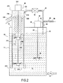
- the first and second propellers 224 and 226 are rotated, the valve 48 of the tubing 44 and the valve 50 of the liquid supply line 46 are open while the draw-off valve 52 is closed.
- the liquid 14 in the tank is represented by the areas hatched by horizontal dashes. We distinguish the immersed parts and the emergent parts.
- the grid area symbolizes the powder and the dotted area symbolizes the residual dust.
- the level N of liquid is between the first propeller 224 and the second propeller 226.
- the first propeller 224 generates a downward flow I.
- the liquid 14 which is located on the surface in the submerged portion of the dispersion tube 20, follows the arrows I and is directed towards the chamber of the tank 11.
- the fluid outside the dispersion tube 20 goes up along the dispersion tube 20 and passes into the free space between the helix 224 and the wall of the tube 210, so as to replace the liquid surface of the submerged portion of the tube dispersion 20.
- the second helix 226 generates a second downward flow II in the emergent portion of the dispersion tube 20.
- the powder and the dust are then force-driven along the arrows II towards the surface of the liquid 14.
- the liquid on the surface of the the submerged portion of the dispersion tube 20 comes into contact with the powder and the dust, mixes with powder and dust, and is then directed into the chamber of the vessel 11 by the first flow I.
- the first downflow I creates a powder / liquid mixing interface
- the second downflow II creates a forced pipe of the powder towards the powder / liquid mixing interface.
- Residual dust (dashed area), suspended above the volume of powder (grid area), is sucked through the dust discharge port 218 by the Venturi effect created by the arrival of liquid in the tubing 44.
- the liquid flowing from the pipe 44 is therefore loaded with dust that would not be filtered by the filter 42.
- the first propeller 224 generates a first downward flow I 'in the extension of the second downflow II' generated by the second propeller 226.
- fluid external to the dispersion tube 20 rises along the latter and passes into the free space between the wall of the tube 210 and the propellers 224 and 226.
- This external fluid renews the fluid surface of the immersed part of the tube dispersion 20, is charged with powder and dust and is redirected to the enclosure of the tank following the downward flow II 'and I'.
- the first downward flow I ' creates a forced pipe of the liquid present in the dispersion tube 20 towards the enclosure of the tank 11 and the second downflow II 'creates a powder / liquid mixing interface.
- the powder is brought by gravity to the surface of the liquid following the arrows II ". figure 1 , the residual dust is sucked through the dust discharge port 218.
- the emergent part of the dispersion tube 20 is maintained at atmospheric pressure, that is to say the pressure on the outside of the tube. dispersion 20, and this, preferably, using the dust discharge port.
- atmospheric pressure that is to say the pressure on the outside of the tube. dispersion 20, and this, preferably, using the dust discharge port.
- the pressure in the emerging part of the Dispersion tube 20 may tend to increase, which may hinder the mixing of the powder and dust with the liquid. It is then advantageous to regulate the pressure in the emergent portion of the dispersion tube 20.
- the opening constituted by the dust discharge orifice can serve to maintain the pressure in the emergent part of the dispersion tube 20 at atmospheric pressure. and avoids harmful overpressures to the mixture of the powder with the liquid.
- the filter 42 then makes it possible to prevent the dust from dispersing in the ambient atmosphere.
- the vacuum for evacuating dust through the dust discharge port improves the maintenance of the pressure in the emergent portion of the dispersion tube at atmospheric pressure.
Landscapes
- Chemical & Material Sciences (AREA)
- Chemical Kinetics & Catalysis (AREA)
- Dispersion Chemistry (AREA)
- Mixers Of The Rotary Stirring Type (AREA)
Applications Claiming Priority (1)
| Application Number | Priority Date | Filing Date | Title |
|---|---|---|---|
| FR0952948A FR2944979B1 (fr) | 2009-05-04 | 2009-05-04 | Dispositif de melange de poudre avec un liquide comprenant un tube de dispersion |
Publications (2)
| Publication Number | Publication Date |
|---|---|
| EP2248576A1 true EP2248576A1 (de) | 2010-11-10 |
| EP2248576B1 EP2248576B1 (de) | 2012-02-08 |
Family
ID=41338522
Family Applications (1)
| Application Number | Title | Priority Date | Filing Date |
|---|---|---|---|
| EP10161788A Not-in-force EP2248576B1 (de) | 2009-05-04 | 2010-05-03 | Vorrichtung zum Mischen von Puder mit einer Flüssigkeit mit einem Dispersionsrohr |
Country Status (4)
| Country | Link |
|---|---|
| US (1) | US8684590B2 (de) |
| EP (1) | EP2248576B1 (de) |
| AT (1) | ATE544508T1 (de) |
| FR (1) | FR2944979B1 (de) |
Families Citing this family (2)
| Publication number | Priority date | Publication date | Assignee | Title |
|---|---|---|---|---|
| FR2944979B1 (fr) * | 2009-05-04 | 2011-05-13 | Sodimate | Dispositif de melange de poudre avec un liquide comprenant un tube de dispersion |
| CN111690809B (zh) * | 2020-06-23 | 2021-11-09 | 重庆中渣冶金再生资源有限公司 | 除尘灰冷化球成型生产线 |
Citations (4)
| Publication number | Priority date | Publication date | Assignee | Title |
|---|---|---|---|---|
| DE9213898U1 (de) * | 1992-10-01 | 1992-12-24 | Wallace & Tiernan GmbH, 8870 Günzburg | Vorrichtung zum Hinzudosieren von Pulver-Aktivkohle in einen Filterkreislauf von Schwimm- oder Badebeckenwasser |
| WO2002092206A2 (en) * | 2001-05-14 | 2002-11-21 | Ciba Specialty Chemicals Water Treatments Limited | Apparatus and method for wetting powder |
| WO2003086565A2 (en) * | 2002-04-11 | 2003-10-23 | Mobius Technologies, Inc. | Apparatus and method for continuously removing air from a mixture of ground polyurethane particles and a polyol liquid |
| US20040218463A1 (en) * | 2003-04-30 | 2004-11-04 | Allen Thomas E. | Gel mixing system |
Family Cites Families (6)
| Publication number | Priority date | Publication date | Assignee | Title |
|---|---|---|---|---|
| US2685499A (en) * | 1950-12-21 | 1954-08-03 | Eastman Kodak Co | Method of proeparing blanc fixe |
| US3911065A (en) * | 1973-04-17 | 1975-10-07 | Ernest J Martin | Liquid aerator or the like |
| JPH07196393A (ja) * | 1993-12-29 | 1995-08-01 | Ishikawajima Harima Heavy Ind Co Ltd | 結晶器 |
| US6585236B2 (en) * | 2001-07-16 | 2003-07-01 | Hitachi Kiden Kogyo, Ltd. | Aerator |
| AU2004317670A1 (en) * | 2003-12-10 | 2005-10-06 | Van Der Berg, Zacharias Joseph | Submersibly operable high volume and low pressure liquid transfer equipment |
| FR2944979B1 (fr) * | 2009-05-04 | 2011-05-13 | Sodimate | Dispositif de melange de poudre avec un liquide comprenant un tube de dispersion |
-
2009
- 2009-05-04 FR FR0952948A patent/FR2944979B1/fr not_active Expired - Fee Related
-
2010
- 2010-05-03 AT AT10161788T patent/ATE544508T1/de active
- 2010-05-03 US US12/772,339 patent/US8684590B2/en not_active Expired - Fee Related
- 2010-05-03 EP EP10161788A patent/EP2248576B1/de not_active Not-in-force
Patent Citations (5)
| Publication number | Priority date | Publication date | Assignee | Title |
|---|---|---|---|---|
| DE9213898U1 (de) * | 1992-10-01 | 1992-12-24 | Wallace & Tiernan GmbH, 8870 Günzburg | Vorrichtung zum Hinzudosieren von Pulver-Aktivkohle in einen Filterkreislauf von Schwimm- oder Badebeckenwasser |
| DE4323371A1 (de) | 1992-10-01 | 1994-04-07 | Wallace & Tiernan Gmbh | Vorrichtung zum Hinzudosieren von Pulver-Aktivkohle in einen Filterkreislauf von Schwimm- oder Badebeckenwasser |
| WO2002092206A2 (en) * | 2001-05-14 | 2002-11-21 | Ciba Specialty Chemicals Water Treatments Limited | Apparatus and method for wetting powder |
| WO2003086565A2 (en) * | 2002-04-11 | 2003-10-23 | Mobius Technologies, Inc. | Apparatus and method for continuously removing air from a mixture of ground polyurethane particles and a polyol liquid |
| US20040218463A1 (en) * | 2003-04-30 | 2004-11-04 | Allen Thomas E. | Gel mixing system |
Also Published As
| Publication number | Publication date |
|---|---|
| US8684590B2 (en) | 2014-04-01 |
| FR2944979A1 (fr) | 2010-11-05 |
| EP2248576B1 (de) | 2012-02-08 |
| US20100278006A1 (en) | 2010-11-04 |
| ATE544508T1 (de) | 2012-02-15 |
| FR2944979B1 (fr) | 2011-05-13 |
Similar Documents
| Publication | Publication Date | Title |
|---|---|---|
| EP2032013B1 (de) | Vorrichtung zum mischen von flüssigkeit und gas | |
| EP2007263A1 (de) | Flüssigkeits-/gastrennvorrichtung, besonders für einen staubsauger | |
| FR3032361A1 (fr) | Melangeur pour aspirer et melanger un produit solide avec un liquide provenant d’une cuve de pulverisateur | |
| FR2929133A1 (fr) | Dispositif de melange comprenant un conduit d'amenee de particules debouchant dans la zone de turbulences | |
| CH628252A5 (fr) | Dispositif pour le melange continu de produits solides a l'etat divise et de produits liquides. | |
| FR2648725A1 (fr) | Procede et dispositif de desaeration de liquides | |
| EP2248576B1 (de) | Vorrichtung zum Mischen von Puder mit einer Flüssigkeit mit einem Dispersionsrohr | |
| EP1442280B1 (de) | Modul zur extraktion eines gases aus untergrundflussigkeit und anlage mit einem solchen modul ausgestattet | |
| CA1219804A (fr) | Installations de nettoyage central par aspiration | |
| FR2596290A1 (fr) | Dispositif pour le melange d'un materiau pulverulent et d'un liquide, ou liquide-liquide | |
| FR2924322A1 (fr) | Aspirateur a filtration a eau | |
| FR2899438A1 (fr) | Dispositif pour separer les uns des autres le pedoncules de fruits regroupes en grappes. | |
| EP1091812B1 (de) | Verfahren zum reinigen eines ölspeichertanks und gerät zur verwirklichung des verfahrens | |
| EP4061591B1 (de) | Mobile vorrichtung zur erfassung eines aus einer düse einer schneidemaschine austretenden hochdruckwasserstrahls | |
| FR2550957A1 (fr) | Dispositif d'alimentation de particules comportant une alimentation de reserve | |
| FR2847791A1 (fr) | Appareil compact de nettoyage de sol | |
| FR2823234A1 (fr) | Dispositif de w.-c. a broyeur | |
| WO2023209308A1 (fr) | Unité de remplissage de coke de pétrole et procédé de remplissage | |
| WO1995021026A1 (fr) | Procede et dispositif de distribution d'un melange d'air comprime et de poudre | |
| BE1032453B1 (fr) | Un module de guidage magnétique à soufflage d'air anti-colmatage et un séparateur magnétique | |
| FR2964891A1 (fr) | Machine a aspiration particulaire a plaque deflectrice. | |
| FR2970660A1 (fr) | Dispositif, installation et procede pour melanger des substances sous forme liquide et/ou pulverulente | |
| FR2498224A1 (fr) | Procede et dispositif de fractionnement et de calibrage des dechets solides en suspension dans les eaux usees | |
| EP1226872A1 (de) | Vorrichtung zum Sortieren eines Gemisches aus metallischen Werkstücken und Schleifpartikeln | |
| CH346529A (fr) | Epurateur d'air |
Legal Events
| Date | Code | Title | Description |
|---|---|---|---|
| PUAI | Public reference made under article 153(3) epc to a published international application that has entered the european phase |
Free format text: ORIGINAL CODE: 0009012 |
|
| AK | Designated contracting states |
Kind code of ref document: A1 Designated state(s): AL AT BE BG CH CY CZ DE DK EE ES FI FR GB GR HR HU IE IS IT LI LT LU LV MC MK MT NL NO PL PT RO SE SI SK SM TR |
|
| AX | Request for extension of the european patent |
Extension state: BA ME RS |
|
| 17P | Request for examination filed |
Effective date: 20110503 |
|
| RIC1 | Information provided on ipc code assigned before grant |
Ipc: B01F 7/24 20060101ALI20110525BHEP Ipc: B01F 7/22 20060101ALI20110525BHEP Ipc: B01F 3/12 20060101AFI20110525BHEP |
|
| GRAP | Despatch of communication of intention to grant a patent |
Free format text: ORIGINAL CODE: EPIDOSNIGR1 |
|
| GRAS | Grant fee paid |
Free format text: ORIGINAL CODE: EPIDOSNIGR3 |
|
| GRAA | (expected) grant |
Free format text: ORIGINAL CODE: 0009210 |
|
| AK | Designated contracting states |
Kind code of ref document: B1 Designated state(s): AL AT BE BG CH CY CZ DE DK EE ES FI FR GB GR HR HU IE IS IT LI LT LU LV MC MK MT NL NO PL PT RO SE SI SK SM TR |
|
| REG | Reference to a national code |
Ref country code: GB Ref legal event code: FG4D Free format text: NOT ENGLISH |
|
| REG | Reference to a national code |
Ref country code: CH Ref legal event code: EP Ref country code: AT Ref legal event code: REF Ref document number: 544508 Country of ref document: AT Kind code of ref document: T Effective date: 20120215 |
|
| REG | Reference to a national code |
Ref country code: DE Ref legal event code: R096 Ref document number: 602010000798 Country of ref document: DE Effective date: 20120405 |
|
| REG | Reference to a national code |
Ref country code: NL Ref legal event code: VDEP Effective date: 20120208 |
|
| LTIE | Lt: invalidation of european patent or patent extension |
Effective date: 20120208 |
|
| PG25 | Lapsed in a contracting state [announced via postgrant information from national office to epo] |
Ref country code: IS Free format text: LAPSE BECAUSE OF FAILURE TO SUBMIT A TRANSLATION OF THE DESCRIPTION OR TO PAY THE FEE WITHIN THE PRESCRIBED TIME-LIMIT Effective date: 20120608 Ref country code: HR Free format text: LAPSE BECAUSE OF FAILURE TO SUBMIT A TRANSLATION OF THE DESCRIPTION OR TO PAY THE FEE WITHIN THE PRESCRIBED TIME-LIMIT Effective date: 20120208 Ref country code: NL Free format text: LAPSE BECAUSE OF FAILURE TO SUBMIT A TRANSLATION OF THE DESCRIPTION OR TO PAY THE FEE WITHIN THE PRESCRIBED TIME-LIMIT Effective date: 20120208 Ref country code: LT Free format text: LAPSE BECAUSE OF FAILURE TO SUBMIT A TRANSLATION OF THE DESCRIPTION OR TO PAY THE FEE WITHIN THE PRESCRIBED TIME-LIMIT Effective date: 20120208 Ref country code: NO Free format text: LAPSE BECAUSE OF FAILURE TO SUBMIT A TRANSLATION OF THE DESCRIPTION OR TO PAY THE FEE WITHIN THE PRESCRIBED TIME-LIMIT Effective date: 20120508 |
|
| REG | Reference to a national code |
Ref country code: IE Ref legal event code: FD4D |
|
| PG25 | Lapsed in a contracting state [announced via postgrant information from national office to epo] |
Ref country code: LV Free format text: LAPSE BECAUSE OF FAILURE TO SUBMIT A TRANSLATION OF THE DESCRIPTION OR TO PAY THE FEE WITHIN THE PRESCRIBED TIME-LIMIT Effective date: 20120208 Ref country code: GR Free format text: LAPSE BECAUSE OF FAILURE TO SUBMIT A TRANSLATION OF THE DESCRIPTION OR TO PAY THE FEE WITHIN THE PRESCRIBED TIME-LIMIT Effective date: 20120509 Ref country code: PT Free format text: LAPSE BECAUSE OF FAILURE TO SUBMIT A TRANSLATION OF THE DESCRIPTION OR TO PAY THE FEE WITHIN THE PRESCRIBED TIME-LIMIT Effective date: 20120608 Ref country code: PL Free format text: LAPSE BECAUSE OF FAILURE TO SUBMIT A TRANSLATION OF THE DESCRIPTION OR TO PAY THE FEE WITHIN THE PRESCRIBED TIME-LIMIT Effective date: 20120208 Ref country code: FI Free format text: LAPSE BECAUSE OF FAILURE TO SUBMIT A TRANSLATION OF THE DESCRIPTION OR TO PAY THE FEE WITHIN THE PRESCRIBED TIME-LIMIT Effective date: 20120208 |
|
| REG | Reference to a national code |
Ref country code: AT Ref legal event code: MK05 Ref document number: 544508 Country of ref document: AT Kind code of ref document: T Effective date: 20120208 |
|
| PG25 | Lapsed in a contracting state [announced via postgrant information from national office to epo] |
Ref country code: CY Free format text: LAPSE BECAUSE OF FAILURE TO SUBMIT A TRANSLATION OF THE DESCRIPTION OR TO PAY THE FEE WITHIN THE PRESCRIBED TIME-LIMIT Effective date: 20120208 |
|
| PG25 | Lapsed in a contracting state [announced via postgrant information from national office to epo] |
Ref country code: SE Free format text: LAPSE BECAUSE OF FAILURE TO SUBMIT A TRANSLATION OF THE DESCRIPTION OR TO PAY THE FEE WITHIN THE PRESCRIBED TIME-LIMIT Effective date: 20120208 Ref country code: EE Free format text: LAPSE BECAUSE OF FAILURE TO SUBMIT A TRANSLATION OF THE DESCRIPTION OR TO PAY THE FEE WITHIN THE PRESCRIBED TIME-LIMIT Effective date: 20120208 Ref country code: CZ Free format text: LAPSE BECAUSE OF FAILURE TO SUBMIT A TRANSLATION OF THE DESCRIPTION OR TO PAY THE FEE WITHIN THE PRESCRIBED TIME-LIMIT Effective date: 20120208 Ref country code: IE Free format text: LAPSE BECAUSE OF FAILURE TO SUBMIT A TRANSLATION OF THE DESCRIPTION OR TO PAY THE FEE WITHIN THE PRESCRIBED TIME-LIMIT Effective date: 20120208 Ref country code: SI Free format text: LAPSE BECAUSE OF FAILURE TO SUBMIT A TRANSLATION OF THE DESCRIPTION OR TO PAY THE FEE WITHIN THE PRESCRIBED TIME-LIMIT Effective date: 20120208 Ref country code: DK Free format text: LAPSE BECAUSE OF FAILURE TO SUBMIT A TRANSLATION OF THE DESCRIPTION OR TO PAY THE FEE WITHIN THE PRESCRIBED TIME-LIMIT Effective date: 20120208 Ref country code: RO Free format text: LAPSE BECAUSE OF FAILURE TO SUBMIT A TRANSLATION OF THE DESCRIPTION OR TO PAY THE FEE WITHIN THE PRESCRIBED TIME-LIMIT Effective date: 20120208 |
|
| BERE | Be: lapsed |
Owner name: SODIMATE Effective date: 20120531 |
|
| PG25 | Lapsed in a contracting state [announced via postgrant information from national office to epo] |
Ref country code: SK Free format text: LAPSE BECAUSE OF FAILURE TO SUBMIT A TRANSLATION OF THE DESCRIPTION OR TO PAY THE FEE WITHIN THE PRESCRIBED TIME-LIMIT Effective date: 20120208 Ref country code: IT Free format text: LAPSE BECAUSE OF FAILURE TO SUBMIT A TRANSLATION OF THE DESCRIPTION OR TO PAY THE FEE WITHIN THE PRESCRIBED TIME-LIMIT Effective date: 20120208 |
|
| PLBE | No opposition filed within time limit |
Free format text: ORIGINAL CODE: 0009261 |
|
| STAA | Information on the status of an ep patent application or granted ep patent |
Free format text: STATUS: NO OPPOSITION FILED WITHIN TIME LIMIT |
|
| PG25 | Lapsed in a contracting state [announced via postgrant information from national office to epo] |
Ref country code: MC Free format text: LAPSE BECAUSE OF NON-PAYMENT OF DUE FEES Effective date: 20120531 |
|
| 26N | No opposition filed |
Effective date: 20121109 |
|
| PG25 | Lapsed in a contracting state [announced via postgrant information from national office to epo] |
Ref country code: AT Free format text: LAPSE BECAUSE OF FAILURE TO SUBMIT A TRANSLATION OF THE DESCRIPTION OR TO PAY THE FEE WITHIN THE PRESCRIBED TIME-LIMIT Effective date: 20120208 |
|
| PG25 | Lapsed in a contracting state [announced via postgrant information from national office to epo] |
Ref country code: MK Free format text: LAPSE BECAUSE OF FAILURE TO SUBMIT A TRANSLATION OF THE DESCRIPTION OR TO PAY THE FEE WITHIN THE PRESCRIBED TIME-LIMIT Effective date: 20120208 Ref country code: BE Free format text: LAPSE BECAUSE OF NON-PAYMENT OF DUE FEES Effective date: 20120531 |
|
| REG | Reference to a national code |
Ref country code: DE Ref legal event code: R097 Ref document number: 602010000798 Country of ref document: DE Effective date: 20121109 |
|
| REG | Reference to a national code |
Ref country code: DE Ref legal event code: R119 Ref document number: 602010000798 Country of ref document: DE Effective date: 20121201 |
|
| PG25 | Lapsed in a contracting state [announced via postgrant information from national office to epo] |
Ref country code: ES Free format text: LAPSE BECAUSE OF FAILURE TO SUBMIT A TRANSLATION OF THE DESCRIPTION OR TO PAY THE FEE WITHIN THE PRESCRIBED TIME-LIMIT Effective date: 20120519 |
|
| PG25 | Lapsed in a contracting state [announced via postgrant information from national office to epo] |
Ref country code: DE Free format text: LAPSE BECAUSE OF NON-PAYMENT OF DUE FEES Effective date: 20121201 |
|
| PG25 | Lapsed in a contracting state [announced via postgrant information from national office to epo] |
Ref country code: BG Free format text: LAPSE BECAUSE OF FAILURE TO SUBMIT A TRANSLATION OF THE DESCRIPTION OR TO PAY THE FEE WITHIN THE PRESCRIBED TIME-LIMIT Effective date: 20120508 Ref country code: MT Free format text: LAPSE BECAUSE OF FAILURE TO SUBMIT A TRANSLATION OF THE DESCRIPTION OR TO PAY THE FEE WITHIN THE PRESCRIBED TIME-LIMIT Effective date: 20120208 |
|
| PG25 | Lapsed in a contracting state [announced via postgrant information from national office to epo] |
Ref country code: AL Free format text: LAPSE BECAUSE OF FAILURE TO SUBMIT A TRANSLATION OF THE DESCRIPTION OR TO PAY THE FEE WITHIN THE PRESCRIBED TIME-LIMIT Effective date: 20120208 |
|
| PG25 | Lapsed in a contracting state [announced via postgrant information from national office to epo] |
Ref country code: TR Free format text: LAPSE BECAUSE OF FAILURE TO SUBMIT A TRANSLATION OF THE DESCRIPTION OR TO PAY THE FEE WITHIN THE PRESCRIBED TIME-LIMIT Effective date: 20120208 |
|
| PG25 | Lapsed in a contracting state [announced via postgrant information from national office to epo] |
Ref country code: SM Free format text: LAPSE BECAUSE OF FAILURE TO SUBMIT A TRANSLATION OF THE DESCRIPTION OR TO PAY THE FEE WITHIN THE PRESCRIBED TIME-LIMIT Effective date: 20120208 Ref country code: LU Free format text: LAPSE BECAUSE OF NON-PAYMENT OF DUE FEES Effective date: 20120503 |
|
| PG25 | Lapsed in a contracting state [announced via postgrant information from national office to epo] |
Ref country code: HU Free format text: LAPSE BECAUSE OF FAILURE TO SUBMIT A TRANSLATION OF THE DESCRIPTION OR TO PAY THE FEE WITHIN THE PRESCRIBED TIME-LIMIT Effective date: 20100503 |
|
| REG | Reference to a national code |
Ref country code: CH Ref legal event code: PL |
|
| PG25 | Lapsed in a contracting state [announced via postgrant information from national office to epo] |
Ref country code: CH Free format text: LAPSE BECAUSE OF NON-PAYMENT OF DUE FEES Effective date: 20140531 Ref country code: LI Free format text: LAPSE BECAUSE OF NON-PAYMENT OF DUE FEES Effective date: 20140531 |
|
| REG | Reference to a national code |
Ref country code: FR Ref legal event code: PLFP Year of fee payment: 6 |
|
| PGFP | Annual fee paid to national office [announced via postgrant information from national office to epo] |
Ref country code: GB Payment date: 20150619 Year of fee payment: 6 |
|
| PGFP | Annual fee paid to national office [announced via postgrant information from national office to epo] |
Ref country code: FR Payment date: 20150513 Year of fee payment: 6 |
|
| GBPC | Gb: european patent ceased through non-payment of renewal fee |
Effective date: 20160503 |
|
| REG | Reference to a national code |
Ref country code: FR Ref legal event code: ST Effective date: 20170131 |
|
| PG25 | Lapsed in a contracting state [announced via postgrant information from national office to epo] |
Ref country code: FR Free format text: LAPSE BECAUSE OF NON-PAYMENT OF DUE FEES Effective date: 20160531 |
|
| PG25 | Lapsed in a contracting state [announced via postgrant information from national office to epo] |
Ref country code: GB Free format text: LAPSE BECAUSE OF NON-PAYMENT OF DUE FEES Effective date: 20160503 |