EP2248600A1 - Procédé de correction de quantité d'éjection et appareil de revêtement - Google Patents
Procédé de correction de quantité d'éjection et appareil de revêtement Download PDFInfo
- Publication number
- EP2248600A1 EP2248600A1 EP09712114A EP09712114A EP2248600A1 EP 2248600 A1 EP2248600 A1 EP 2248600A1 EP 09712114 A EP09712114 A EP 09712114A EP 09712114 A EP09712114 A EP 09712114A EP 2248600 A1 EP2248600 A1 EP 2248600A1
- Authority
- EP
- European Patent Office
- Prior art keywords
- droplet
- image
- target surface
- mirror
- application target
- Prior art date
- Legal status (The legal status is an assumption and is not a legal conclusion. Google has not performed a legal analysis and makes no representation as to the accuracy of the status listed.)
- Granted
Links
Images




Classifications
-
- B—PERFORMING OPERATIONS; TRANSPORTING
- B05—SPRAYING OR ATOMISING IN GENERAL; APPLYING FLUENT MATERIALS TO SURFACES, IN GENERAL
- B05C—APPARATUS FOR APPLYING FLUENT MATERIALS TO SURFACES, IN GENERAL
- B05C11/00—Component parts, details or accessories not specifically provided for in groups B05C1/00 - B05C9/00
- B05C11/10—Storage, supply or control of liquid or other fluent material; Recovery of excess liquid or other fluent material
- B05C11/1002—Means for controlling supply, i.e. flow or pressure, of liquid or other fluent material to the applying apparatus, e.g. valves
- B05C11/1005—Means for controlling supply, i.e. flow or pressure, of liquid or other fluent material to the applying apparatus, e.g. valves responsive to condition of liquid or other fluent material already applied to the surface, e.g. coating thickness, weight or pattern
-
- H—ELECTRICITY
- H05—ELECTRIC TECHNIQUES NOT OTHERWISE PROVIDED FOR
- H05K—PRINTED CIRCUITS; CASINGS OR CONSTRUCTIONAL DETAILS OF ELECTRIC APPARATUS; MANUFACTURE OF ASSEMBLAGES OF ELECTRICAL COMPONENTS
- H05K3/00—Apparatus or processes for manufacturing printed circuits
- H05K3/30—Assembling printed circuits with electric components, e.g. with resistors
- H05K3/32—Assembling printed circuits with electric components, e.g. with resistors electrically connecting electric components or wires to printed circuits
- H05K3/34—Assembling printed circuits with electric components, e.g. with resistors electrically connecting electric components or wires to printed circuits by soldering
- H05K3/3465—Application of solder
- H05K3/3485—Application of solder paste, slurry or powder
-
- H—ELECTRICITY
- H10—SEMICONDUCTOR DEVICES; ELECTRIC SOLID-STATE DEVICES NOT OTHERWISE PROVIDED FOR
- H10P—GENERIC PROCESSES OR APPARATUS FOR THE MANUFACTURE OR TREATMENT OF DEVICES COVERED BY CLASS H10
- H10P72/00—Handling or holding of wafers, substrates or devices during manufacture or treatment thereof
- H10P72/04—Apparatus for manufacture or treatment
- H10P72/0402—Apparatus for fluid treatment
-
- B—PERFORMING OPERATIONS; TRANSPORTING
- B05—SPRAYING OR ATOMISING IN GENERAL; APPLYING FLUENT MATERIALS TO SURFACES, IN GENERAL
- B05C—APPARATUS FOR APPLYING FLUENT MATERIALS TO SURFACES, IN GENERAL
- B05C11/00—Component parts, details or accessories not specifically provided for in groups B05C1/00 - B05C9/00
- B05C11/10—Storage, supply or control of liquid or other fluent material; Recovery of excess liquid or other fluent material
-
- H—ELECTRICITY
- H05—ELECTRIC TECHNIQUES NOT OTHERWISE PROVIDED FOR
- H05K—PRINTED CIRCUITS; CASINGS OR CONSTRUCTIONAL DETAILS OF ELECTRIC APPARATUS; MANUFACTURE OF ASSEMBLAGES OF ELECTRICAL COMPONENTS
- H05K1/00—Printed circuits
- H05K1/02—Details
- H05K1/0266—Marks, test patterns or identification means
- H05K1/0269—Marks, test patterns or identification means for visual or optical inspection
-
- H—ELECTRICITY
- H10—SEMICONDUCTOR DEVICES; ELECTRIC SOLID-STATE DEVICES NOT OTHERWISE PROVIDED FOR
- H10P—GENERIC PROCESSES OR APPARATUS FOR THE MANUFACTURE OR TREATMENT OF DEVICES COVERED BY CLASS H10
- H10P72/00—Handling or holding of wafers, substrates or devices during manufacture or treatment thereof
- H10P72/04—Apparatus for manufacture or treatment
- H10P72/0448—Apparatus for applying a liquid, a resin, an ink or the like
Definitions
- the present invention relates to a method for correcting changes in ejection amount of a liquid material, which are caused due to, e.g., changes in viscosity of the liquid material with the lapse of time, and to an applying apparatus. More particularly, the present invention relates to a method for measuring the amount of a droplet of the liquid material applied to a substrate and correcting the ejection amount of the liquid material based on the measured value, and to an applying apparatus.
- Patent Document 1 an ejection amount correction method of measuring the weight of the liquid material by using an electronic scale
- Patent Document 2 a device for picking up an image of a droplet of the liquid material and measuring the amount of the droplet based on the picked-up image
- Patent Document 1 discloses an ejection amount correction method comprising the steps of periodically measuring the weight of the ejected material, comparing the measured weight with a specified weight, and when the measured weight and the specified weight differ from each other, making control for correcting a number of pulses and a pulse frequency, which are used to drive a pulse motor pump, such that the measured weight comes closer to the specified weight.
- Patent Document 2 discloses an application amount adjustment method comprising the steps of registering a target application amount, supplying a gas pressure to a syringe to eject a bond from a nozzle for a trial application, recognizing the bond applied for a trial and calculating the magnitude of the application amount, comparing the calculated trial application amount with the target application amount to determine whether the difference between both the amounts is within an allowable error, and when the difference is not within the allowable error, repeating the above-mentioned steps while changing the magnitude of the gas pressure supplied to the syringe or a time during which the gas pressure is supplied to the syringe.
- Patent Document 1 has the problem that, because the liquid material is received on a saucer, the measured value is not stabilized until fluctuations of the liquid surface is settled, and hence a relatively long time is taken to obtain the result of the measurement.
- a similar disadvantage is additionally caused with vibration of an apparatus and an influence of a downflow (i.e., an air flow blown from an air conditioner disposed in an upper portion of the apparatus for the purpose of maintaining the interior of the apparatus to be clean).
- a downflow i.e., an air flow blown from an air conditioner disposed in an upper portion of the apparatus for the purpose of maintaining the interior of the apparatus to be clean.
- the invention described in Patent Document 2 because the amount of the droplet is calculated based on a silhouette of the liquid material recognized by a camera from above, the height of the droplet cannot be recognized and the amount of the droplet cannot be correctly calculated.
- An object of the present invention is to provide an ejection amount correction method and an applying apparatus, which can correctly measure the amount of an applied droplet and accurately correct the ejection amount.
- an ejection amount correction method for measuring the amount of a liquid material ejected from a nozzle and correcting the ejection amount of the liquid material, wherein a mirror is set near an application target surface at a predetermined angle with respect to the application target surface, an image of a droplet formed on the application target surface is picked up from a side through the mirror, the volume of the droplet is calculated based on the picked-up image of the droplet, and the ejection amount is corrected based on the calculated volume.
- the mirror includes a plurality of mirrors arranged in orthogonal or symmetrical relation, the image of the droplet is picked up plural times at different angles in a horizontal direction, and the volume of the droplet is calculated based on the picked-up plural images of the droplet.
- the droplet formed on the application target surface or the mirror is rotated, the image of the droplet is picked up plural times at different angles in a horizontal direction, and the volume of the droplet is calculated based on the picked-up plural images of the droplet.
- the volume of the droplet is calculated based on an area of a silhouette of the droplet as viewed from a side.
- the volume of the droplet is calculated based on a height and a width of a silhouette of the droplet as viewed from a side.
- an image of the silhouette of the droplet as viewed from above is picked up, and when roundness of the silhouette as viewed from above exceeds an allowable range, the droplet is formed again on the application target surface.
- an image of the application target surface before forming the droplet on the application target surface is picked up from a side through the mirror, a boundary line of the application target surface is stored based on the picked-up image of the application target surface, and the volume of the droplet is calculated for a region of the picked-up image of the droplet, which is positioned above the boundary line.
- the predetermined angle is 45 degrees.
- an apparatus for applying a liquid material comprising a reservoir for reserving the liquid material, an ejection device provided with a nozzle for ejecting the liquid material, an image pickup device for picking up an image of a droplet applied to an application target surface, a mirror set near the application target surface at a predetermined angle with respect to the application target surface, and a control unit, wherein the image pickup device and the mirror are arranged at a position capable of picking up the image of the droplet formed on the application target surface from a side.
- the apparatus according to the ninth aspect further comprises a light source disposed in opposed relation to the mirror.
- the mirror includes a plurality of mirrors arranged in orthogonal or symmetrical relation, and the image pickup device is positioned to be capable of picking up images of the droplet through the mirror at different angles in a horizontal direction.
- the apparatus according to any one of the ninth to eleventh aspects further comprises a stage for rotating the droplet formed on the application target surface.
- the apparatus according to any one of the ninth to eleventh aspects further comprises a mirror that is rotatable with respect to the droplet formed on the application target surface.
- the apparatus according to the ninth or tenth aspect further comprises a conveying mechanism capable of moving the substrate in one direction, wherein the mirror is set near the conveying mechanism.
- the apparatus according to any one of the ninth to fourteenth aspects the predetermined angle is 45 degrees.
- the ejection amount can be accurately corrected. Further, with the present invention, the amount of the droplet can be simply measured in principle.
- an "ejection pressure P" of a jet-type ejection device means a total length representing a distance through which a nozzle and a substrate are moved relative to each other
- the term "ejection amount” means the amount of the liquid material ejected in one cycle of ejection work.
- a correction period i.e., a timing at which the ejection amount is to be corrected, is set.
- the correction period is set, for example, as time information or the number of substrates 109 to be processed, which is input by a user.
- a predetermined time is set at which a change in the ejection amount of the liquid material is expected to exceed an allowable range, counting from the start of the work.
- the number of substrates is set, the number of substrates processed is determined from a time required for processing one substrate 109 (i.e., a time required for loading, application and unloading of one substrate) and the above-mentioned predetermined time, and is then set.
- the shape of the droplet 201, as viewed in the horizontal direction, applied onto the substrate is picked up as an image, and a measured volume V 1 of the ejected droplet is calculated from data of the picked-up image.
- an image pickup device 108 is moved to a position above a mirror 107, which is set near the substrate (106 or 109) at a predetermined angle with respect to the application target surface of the substrate, and an image of the shape of the droplet 201 is picked up in the direction parallel to the application target surface.
- a planar light source or a planar member serving as a background which has a predetermined area, is preferably disposed in front of the mirror 107.
- a geometrical quantity of the projected surface in the horizontal direction (i.e., in the direction parallel to the application target surface) is calculated based on data of the picked-up image, and the measured volume V 1 of the ejected droplet is calculated based on the calculated geometrical quantity of the projected surface in the horizontal direction.
- the change rate R When the change rate R is minus, the setting of the ejection pressure in consideration of an increase of the ejection amount corresponding to the minus change rate R is obtained from the "relationship between the ejection pressure and the ejection volume", which has been stored in above [1].
- the change rate R is plus, the setting of the ejection pressure in consideration of a decrease of the ejection amount corresponding to the plus change rate R is obtained from the "relationship between the ejection pressure and the ejection volume", which has been stored in above [1].
- the correction of the ejection amount is preferably executed only when the calculated volume difference or the change rate R exceeds an allowable range (e.g., ⁇ 5 %),.
- an allowable range e.g., ⁇ 5 %
- a preferred embodiment of the correction in the case of setting the allowable range is described in detail, for example, in Japanese Patent No. 3877038 that is issued on the basis of a patent application field by the applicant.
- an allowable range for determining whether correction is to be made or not is set, and the ejection pressure is corrected only when a differential value or a change rate R exceeds the allowable range.
- the steps of above [3] and [4] are executed, for example, at the timing of the correction period set in above [2], or when the type (size or shape) of the substrate 109 is changed.
- the liquid material can be always applied in the optimum ejection amount regardless of time-dependent changes in viscosity of the liquid material.
- the ejection device used in the present invention is not limited to the jet-type ejection device described above, and the present invention can be carried out in various types of ejection devices for ejecting the liquid material.
- the control parameter to be adjusted is not limited to the ejection pressure, and it may be any suitable one of the following examples.
- a time during which a piston is ascended, or a time during which the piston is descended may be adjusted.
- the number of rotations of the screw may be adjusted.
- the distance through which the plunger is moved may be adjusted.
- An applying apparatus 101 includes, as illustrated in Fig. 1 , an ejection device 301, an image pickup device 108, an XYZ drive mechanism 102, a conveying mechanism 103, an adjustment mechanism 401 positioned near the conveying mechanism 103, and a control unit 104 for controlling operations of the former components.
- the ejection device 301 includes a reservoir 303 for reserving the liquid material and a nozzle 304 for ejecting the liquid material.
- the ejection device 301 is mounted to the XYZ drive mechanism 102 and is movable to a location above the substrate 109 as an application target and a location above the substrate 106 for adjustment.
- the image pickup device 108 is a device for picking up an image of the droplet ejected onto the substrate.
- a CCD camera is used as the image pickup device 108 in consideration of that data of the picked-up image is subjected to image processing.
- the image pickup device 108 is mounted to the XYZ drive mechanism 102 such that an objective surface 110 through which the image is captured is in opposed relation to the application target surface of the substrate (106, 109).
- the image pickup device 108 is also movable to a location above the substrate 109 as an application target and a location above the substrate 106 for adjustment, as well as to a location above the mirror 107.
- the image pickup device 108 is movable in the Z-direction for adjustment of the focal length. Further, in this embodiment, the image pickup device 108 serves also as a later-described camera for recognizing the position of the substrate. Such dual use of one camera is effective in saving an installation space and in reducing the size of the applying apparatus 101. Be it noted that when the image pickup device 108 is mounted to the XYZ drive mechanism 102, it may be integrally provided at a side of the ejection device 301 as illustrated in Fig. 1 , or may be provided independently of the ejection device 301.
- the adjustment mechanism 401 includes the substrate 106 for adjustment, an adjustment stage 105 on which the substrate 106 for adjustment is placed, the mirror 107 set near the substrate 106 for adjustment, and a light source 111.
- the substrate 106 for adjustment is a substrate used for measuring the amount of the liquid material ejected from the nozzle 304.
- the substrate 106 for adjustment is placed at the same level as the application target substrate 109. The reason resides in that such an arrangement can eliminates the necessity of adjustment of the focal length between recognition of the substrate in a positioning step and the image pick-up in a volume calculation step, when the image pickup device 108 is used also as the camera for recognizing the position of the substrate.
- the setting of the position in the Z-direction can be shared, whereby time and labor required for making separate settings for the substrates 106 and 109 can be saved.
- the mirror 107 is set at an angle ⁇ near the substrate 106 for adjustment. More specifically, the mirror 107 is set such that its surface reflecting an image is inclined at the angle ⁇ with respect to the application target surface of the substrate 106 for adjustment (i.e., the objective surface 110 of the image pickup device 108).
- the mirror 107 is set at the angle ⁇ , a side image of the droplet 201 applied to the substrate (106, 109) can be picked up by the image pickup device 108 after being reflected by the mirror 107.
- the mirror 107 is set at such a height that the image of the droplet 201 is reflected at the center of the mirror 107 (see Fig. 2 ).
- the light source 111 is a flat light (planar light source) that is arranged in a confronting relation to the mirror 107 with the substrate 106 for adjustment interposed between them.
- the light source 111 can be constituted by a known light source, e.g., an LED. Irradiating light toward the mirror 107 from the light source 111 is effective in making a silhouette of the droplet 201 clearer.
- the surface of the mirror 107 reflecting the image is preferably inclined at the angle ⁇ of 45 degrees with respect to the application target surface of the substrate (106, 109).
- the angle ⁇ By setting the angle ⁇ to be 45 degrees, the image of the droplet 201, as viewed in the horizontal direction, applied to the substrate (106, 109) can be reflected in the vertical direction, and the image of the droplet shape can be picked up without causing distortion, such as skewing.
- the side image of the droplet is made incident upon the image pickup device by using one mirror, a plurality of mirrors may be used to transfer the side image of the droplet to the image pickup device.
- the substrate 109 as the application target is first conveyed by the conveying mechanism 103 to a location under the ejection device 301.
- the application of the liquid material by the ejection device 301 is started after the substrate 109 has been conveyed to a location under the nozzle 304 and positioning of the substrate 109 has been finished.
- a locus along which the nozzle 304 is to be moved during the application operation i.e., an application pattern, is previously stored in a storage device (e.g., a memory) inside the control unit 104.
- the substrate 109 is unloaded to the exterior of the applying apparatus 101 by the conveying mechanism 103. Subsequently, the next substrate 109 is loaded and the application work is repeated.
- the application work is repeated until the application of the liquid material to the desired number of substrates 109 is completed, while the loading, the application, and the unloading are carried out as one cycle.
- the correction of the ejection amount is performed at the timing of the preset correction period. In other words, the ejection amount that has changed due to the change in viscosity of the liquid material is corrected.
- the correction amount is calculated by moving the nozzle 304 to the location above the substrate 106 for adjustment with the XYZ drive mechanism 102, and by calculating the volume of the droplet 201 based on the data of the picked-up image of the droplet 201 that has been applied onto the substrate 106 for adjustment. Details of a correction procedure will be described later.
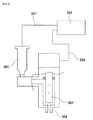
- the ejection device 301 While various types of devices are usable as the ejection device 301, a jet-type ejection device illustrated in Fig. 3 is used in this embodiment.
- the ejection device 301 illustrated in Fig. 3 , includes a piston 302 disposed within the ejection device 301 in a vertically movable state, a reservoir 303 for reserving the liquid material, and the nozzle 304 communicating with the reservoir.
- the liquid material in the reservoir 303 is pressurized by compressed gas that is under regulated pressure and that is supplied from the ejection control unit 305 via a compressed air supply line 307.
- the liquid material 210 supplied from the reservoir 303 to a piston chamber is ejected in the form of a droplet from the nozzle 304 by vertically reciprocating the piston 302 in accordance with an ejection signal, which is sent from the ejection control unit 305.
- the droplet 201 having been ejected from the nozzle 304 is applied in the form of a dot to the substrate (106, 109), which is positioned under the nozzle 304.
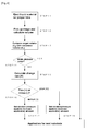
- a correction procedure 1 in this embodiment is described with reference to a flowchart of Fig. 4 .
- a proper ejection time required for ejecting the liquid material in the target volume which is obtained based on the relationship between the ejection pressure and the ejection volume, is calculated and the liquid material is ejected onto the substrate for the proper ejection time (STEP 11).
- the shape of the droplet 201 as viewed in the horizontal direction i.e., the shape of the droplet as viewed in the direction parallel to the application target surface of the substrate
- the measured volume V 1 of the droplet 201 is calculated from the picked-up image (STEP 12).
- the measured volume V 1 and the target volume V 0 are compared with each other (STEP 13), and the necessity of correction is determined depending on whether the volume difference exceeds the allowable range (STEP 14).
- the change rate R is minus, this means that the measured volume V 1 is less than the target volume V 0 . Therefore, the control parameter in consideration of an increase of the measured volume V 1 corresponding to the minus change rate R is calculated from the control data which has been stored in the control unit 104 in advance, to thereby set the ejection pressure again (STEP 17).
- the setting parameter in consideration of an decrease of the ejection volume V 1 corresponding to the plus change rate R is calculated from the control data which has been stored in the control unit 104, to thereby set the ejection pressure again (STEP 18).
- the necessity of correction may be determined by calculating only the change rate R without calculating the volume difference. In such a case, STEP 14 is not executed, and the determination is made between STEP 13 to STEP 15 and STEP 16.
- a step of calculating roundness of the shape of the droplet 201 on a projected surface as viewed in the vertical direction (i.e., the silhouette of the droplet in a plan), and determining whether a calculated value falls within an allowable range may be added.
- a correction procedure 2 in this embodiment is described with reference to a flowchart of Fig. 5 in addition to the flowchart of Fig. 4 .
- the liquid material is ejected onto the substrate for the proper ejection time (STEP 21).
- the shape of the ejected droplet 201 as viewed in the vertical direction relative to the application target surface of the substrate i.e., the shape of the droplet 201 as viewed from above the application target surface
- the roundness of the droplet 201 is calculated from the picked-up image.
- the roundness is calculated from a difference between a maximum length and a minimum length of a linear line passing the center of gravity of the shape of the droplet 201 on a projected surface as viewed in the vertical direction relative to the application target surface of the substrate.
- the control flow advances to STEP 12 in Fig. 4 .
- the volume of the droplet 201 is calculated and the correction of the ejection amount is executed.
- the control flow returns to STEP 21 in which the liquid material is ejected again.
- a predetermined number of times may be set for the return to STEP 21 and an alarm may be issued upon determining the occurrence of an error when the number of returns exceeds the predetermined number of times.
- the applying apparatus of this embodiment since the image of the droplet 201 is picked up from a side with the aid of the mirror 107, the shape of the droplet 201 can be more correctly captured and hence the volume of the droplet 201 can be more accurately measured.
- the applying apparatus of this embodiment can realize saving of an installation space and reduction of the apparatus size because the necessity of separately installing an additional image pickup device to pick up the image of the droplet 201 is eliminated as a result of using the mirror 107.
- An applying apparatus of Embodiment 2 differs from the applying apparatus of Embodiment 1 in that the adjustment mechanism 401 includes two mirrors 107.
- the applying apparatus of this embodiment as illustrated in Fig. 8 , two mirrors 107 are set be able to pick up images of the shape of the droplet 201 as viewed in two directions that are parallel to the application target surface of the substrate and that are orthogonal to each other.
- the two mirrors 107 are set at the same angle ⁇ as in Embodiment 1. Further, the two mirrors 107 are set such that their surfaces reflecting respective images are oriented in mutually orthogonal relation with respect to the substrate 106 for adjustment.
- two light sources 111 are required.
- the two light sources 11 may be constituted by using physically-separate two light sources, or by dividing light from one light source to two rays through an optical system, which are illuminated toward the two mirrors.
- the image pickup device 108 When the image of the droplet 201 applied onto the substrate 106 is picked up, the image pickup device 108 is first moved to a location above one mirror 107 where the image of the shape of the droplet 201 on the projected plane as viewed in the horizontal direction (i.e., the side image thereof) is picked up. Next, the image pickup device 108 is moved to a location above the other mirror 107 where the image of the shape of the droplet 201 on the projected plane is picked up in a direction perpendicular to the projected plane for which the image has been first picked up. Further, values (r or d) calculated from respective lengths of bottom sides of the two picked-up images are compared with each other.
- the volume of the droplet is calculated by assuming the droplet to be a half sphere. If those lengths differ from each other, the volume of the droplet is calculated by assuming the droplet to be a half ellipsoid.
- the images of the droplet 201 picked up in two directions orthogonal to each other can be obtained. Therefore, the shape of the droplet 201 can be more correctly captured and hence the volume of the droplet 201 can be more accurately measured.
- An applying apparatus of Embodiment 3 is similar to the applying apparatus of Embodiment 1 in that the number of mirrors 107 set near the substrate 106 at a certain angle with respect to the application target surface of the substrate is one and the one mirror 107 is set at the angle ⁇ , but it differs from the applying apparatus of Embodiment 1 in that the apparatus includes a rotation drive mechanism 901 for rotating an adjustment stage 105.
- the adjustment mechanism 401 of this embodiment as illustrated in Fig. 9 , the adjustment stage 105 is rotated relative to the mirror 107 by the rotation drive mechanism 901 that is provided under the adjustment stage 105.
- the adjustment stage 105 is rotatable, the image of the droplet 201 as viewed in the horizontal direction can be picked up in two or more directions.
- the image of the droplet 201 applied onto the substrate 106 is picked up as follows. First, the image pickup device 108 is moved to the location above the set mirror 107 where the image of the shape of the droplet 201 on the projected plane is picked up as viewed in the horizontal direction relative to the application target surface of the substrate. Next, the adjustment stage 105 is rotated while the position of the image pickup device 108 is held fixed.
- an amount of the rotation of the adjustment stage 105 can be optionally selected, it is here assumed that the rotation amount is 90 degrees (corresponding to the case where the number of image pickups is two) or 120 degrees (corresponding to the case where the number of image pickups is three).
- the side image of the droplet 201 is picked up in one or more different rotational positions.
- a method of calculating the volume from two or more picked-up images is similar to that described above in Embodiment 2.
- the arrangement of this embodiment including the rotatable adjustment stage 105 as described above, since the images of the droplet 201 picked up in two or more directions are picked up, the shape of the droplet 201 can be more correctly captured and hence the volume of the droplet 201 can be more accurately measured.
- the arrangement may be modified such that the mirror is rotated with respect to the substrate without rotating the substrate. However, such a modified arrangement requires a light source or an optical system for causing light to enter the mirror in a way following the rotation of the mirror.
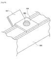
- An applying apparatus of Embodiment 4 includes, as illustrated in Fig. 10 , a mirror 107 disposed adjacent to the conveying mechanism 103 that is able to move the substrate 109 in one direction.
- the mirror 107 is disposed near the location where positioning of the application target substrate 109 placed on the stage is performed.
- a light source 111 (not shown) is disposed in opposed relation to the mirror 107 with the stage interposed between them.
- the image of the droplet 201 applied onto the substrate 106 is picked up in a similar manner to that in Embodiment 1, and a method for calculating the volume of the droplet 201 is also similar to that in Embodiment 1.
- the volume of the droplet 201 is calculated by picking up the image of the droplet 201 applied to the application target substrate 109. Therefore, the time taken for applying the droplet to the substrate 106 for adjustment and the time taken for picking up the image of the substrate 106 for adjustment are no longer required, whereby the time taken for the correction can be cut.
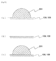
- a focus is not matched with the substrate when focusing is made on the droplet, and the boundary between the droplet and the substrate, i.e., an edge of the upper surface of the substrate, may become not sharp in the picked-up image ( Fig. 11 (a) ).
- a boundary line is blurred and an error is caused in recognition of the image and in calculation of the volume in some cases.
- the following method is executed for the purpose of more accurate measurement. First, as a preparation step, an image of the substrate before applying the droplet thereto is picked up, and a boundary line of the upper surface of the substrate is recognized and stored ( Fig.
- the recognition of the image and the calculation of the volume are executed based on the boundary line that has been stored in the preparation step.
- the volume is calculated by recognizing only an image in a region above the boundary line that has been stored in the preparation step ( Fig. 11(c) ).
- the present invention can be practiced in various types of devices for ejecting liquid materials.
- Examples of an ejection device of the type in which the liquid material comes into contact with the substrate before departing from the ejection device include the air type imposing air under regulated pressure for a predetermined time to the liquid material in a syringe that has a nozzle at its fore end, the tubing type including a flat tubing mechanism or a rotary tubing mechanism, the plunger type moving a plunger, which slides in close contact with an inner surface of a reservoir having a nozzle at its fore end, through a desired distance, thereby ejecting the liquid material, the screw type ejecting the liquid material with rotation of a screw, and the valve type controllably ejecting the liquid material, which is under a desired pressure, with opening/closing of a valve.
- examples of an ejection device of the type in which the liquid material comes into contact with the substrate after having departed from the ejection device include the jet type striking a valve body against a valve seat, thereby causing the liquid material to eject in a way flying from the fore end of a nozzle, the plunger jet type moving a plunger-type plunger and then abruptly stopping the plunger, thereby causing the liquid material to eject in a way flying from the fore end of a nozzle, and the ink jet type operating in a continuous jet mode or on demand.
- the present invention can be practiced in various applying apparatuses for applying liquid materials in specified application amounts.
- the present invention can be practiced in a sealant applying apparatus and a liquid crystal dripping apparatus, which are used in steps of manufacturing a liquid crystal panel, as well as in an apparatus for applying a solder paste onto a printed board.
Landscapes
- Engineering & Computer Science (AREA)
- Microelectronics & Electronic Packaging (AREA)
- Coating Apparatus (AREA)
- Manufacturing & Machinery (AREA)
- Application Of Or Painting With Fluid Materials (AREA)
Applications Claiming Priority (2)
| Application Number | Priority Date | Filing Date | Title |
|---|---|---|---|
| JP2008042061 | 2008-02-22 | ||
| PCT/JP2009/000694 WO2009104398A1 (fr) | 2008-02-22 | 2009-02-19 | Procédé de correction de quantité d'éjection et appareil de revêtement |
Publications (3)
| Publication Number | Publication Date |
|---|---|
| EP2248600A1 true EP2248600A1 (fr) | 2010-11-10 |
| EP2248600A4 EP2248600A4 (fr) | 2012-05-16 |
| EP2248600B1 EP2248600B1 (fr) | 2017-12-06 |
Family
ID=40985286
Family Applications (1)
| Application Number | Title | Priority Date | Filing Date |
|---|---|---|---|
| EP09712114.9A Active EP2248600B1 (fr) | 2008-02-22 | 2009-02-19 | Procédé de correction de quantité d'éjection et appareil de revêtement |
Country Status (7)
| Country | Link |
|---|---|
| US (1) | US9144820B2 (fr) |
| EP (1) | EP2248600B1 (fr) |
| JP (1) | JP5431172B2 (fr) |
| KR (2) | KR101643217B1 (fr) |
| CN (1) | CN101952049B (fr) |
| TW (1) | TWI501814B (fr) |
| WO (1) | WO2009104398A1 (fr) |
Cited By (1)
| Publication number | Priority date | Publication date | Assignee | Title |
|---|---|---|---|---|
| WO2019094282A1 (fr) * | 2017-11-10 | 2019-05-16 | Nordson Corporation | Systèmes et procédés pour des commandes améliorées de distribution d'un revêtement |
Families Citing this family (36)
| Publication number | Priority date | Publication date | Assignee | Title |
|---|---|---|---|---|
| JP5535561B2 (ja) * | 2009-09-15 | 2014-07-02 | 日本発條株式会社 | 接着剤塗布装置 |
| JP2011148131A (ja) * | 2010-01-20 | 2011-08-04 | Seiko Epson Corp | 流体吐出装置における流体吐出不良検査方法、および流体吐出不良検査装置 |
| JP5840959B2 (ja) * | 2012-01-16 | 2016-01-06 | エムテックスマート株式会社 | 塗布方法及び装置 |
| KR102031728B1 (ko) * | 2012-11-12 | 2019-10-14 | 세메스 주식회사 | 기판 처리 장치 |
| TWI578042B (zh) * | 2013-03-07 | 2017-04-11 | 鴻海精密工業股份有限公司 | 光通訊模組組裝裝置 |
| JP2014175563A (ja) * | 2013-03-12 | 2014-09-22 | Panasonic Corp | ペースト塗布装置 |
| EP2974566B1 (fr) | 2013-03-13 | 2018-05-09 | Mycronic AB | Procédé et dispositif permettant d'éjecter des gouttelettes |
| JP6020829B2 (ja) * | 2013-10-22 | 2016-11-02 | 株式会社村田製作所 | 塗液観察方法、塗布方法、塗液観察装置および塗布装置 |
| JP6339882B2 (ja) * | 2014-07-09 | 2018-06-06 | ヤマハ発動機株式会社 | 塗布装置 |
| KR102388619B1 (ko) * | 2014-12-01 | 2022-04-21 | 세메스 주식회사 | 기판 처리 장치 및 방법 |
| JP6540021B2 (ja) * | 2014-12-26 | 2019-07-10 | カシオ計算機株式会社 | プリント装置、プリント装置の動作制御方法及びプリント装置の動作制御プログラム |
| JP6452147B2 (ja) * | 2015-01-19 | 2019-01-16 | 武蔵エンジニアリング株式会社 | 液体材料吐出装置 |
| KR102422256B1 (ko) * | 2015-01-30 | 2022-07-19 | 세메스 주식회사 | 검사 유닛 및 검사 방법, 이를 포함하는 기판 처리 장치 |
| CN105459601B (zh) * | 2016-01-15 | 2017-08-01 | 京东方科技集团股份有限公司 | 墨滴体积的校准方法及其校准系统、打印设备 |
| JP6539600B2 (ja) * | 2016-02-16 | 2019-07-03 | ヤマハ発動機株式会社 | 塗布方法、及び、塗布装置 |
| JP6778426B2 (ja) * | 2016-09-20 | 2020-11-04 | 武蔵エンジニアリング株式会社 | 液体材料吐出装置 |
| JP2018051478A (ja) | 2016-09-29 | 2018-04-05 | セイコーエプソン株式会社 | 流体吐出装置および流体を吐出する方法 |
| JP6772725B2 (ja) | 2016-09-29 | 2020-10-21 | セイコーエプソン株式会社 | 流体吐出装置および流体を吐出する方法 |
| JP2018051479A (ja) * | 2016-09-29 | 2018-04-05 | セイコーエプソン株式会社 | 流体吐出装置および流体を吐出する方法 |
| JP2018067375A (ja) * | 2016-10-17 | 2018-04-26 | 住友電装株式会社 | 防食剤供給状態検査装置、防食剤供給装置及び端子付電線の製造方法 |
| US10906058B2 (en) * | 2017-01-27 | 2021-02-02 | Nordson Corporation | Systems and methods for inspecting and cleaning a nozzle of a dispenser |
| KR102038645B1 (ko) * | 2017-06-23 | 2019-10-30 | 참엔지니어링(주) | 토출장치 및 이의 검사방법 |
| JP6563984B2 (ja) * | 2017-08-09 | 2019-08-21 | マイクロニック アーベーMycronic Ab | 液滴噴射方法及び液滴噴射装置 |
| KR20200144198A (ko) | 2019-06-17 | 2020-12-29 | 삼성디스플레이 주식회사 | 잉크 액적 부피 측정장치와, 그것을 이용한 잉크 액적 부피 측정방법과, 그 잉크 액적 부피 측정장치를 활용하는 박막층 형성장치 및, 상기 박막층 형성장치를 이용한 디스플레이 장치의 제조방법 |
| US11637031B2 (en) | 2019-11-04 | 2023-04-25 | Tokyo Electron Limited | Systems and methods for spin process video analysis during substrate processing |
| JP7433433B2 (ja) * | 2019-11-27 | 2024-02-19 | ビーエーエスエフ コーティングス ゲゼルシャフト ミット ベシュレンクテル ハフツング | ベル形液体噴霧の形状を評価する方法 |
| US11624607B2 (en) | 2020-01-06 | 2023-04-11 | Tokyo Electron Limited | Hardware improvements and methods for the analysis of a spinning reflective substrates |
| JP7671558B2 (ja) | 2020-03-10 | 2025-05-02 | 東京エレクトロン株式会社 | トラックシステムに統合するための長波赤外線熱センサ |
| JP7467176B2 (ja) | 2020-03-16 | 2024-04-15 | 日本発條株式会社 | 接着剤の塗布方法および塗布装置 |
| KR102800515B1 (ko) * | 2020-06-30 | 2025-04-28 | 삼성디스플레이 주식회사 | 표시 장치의 제조장치 및 표시 장치의 제조방법 |
| DE102020211702A1 (de) * | 2020-09-18 | 2022-03-24 | Carl Zeiss Microscopy Gmbh | Verfahren zum Überwachen einer Immersionsflüssigkeit in einem Mikroskop |
| KR20220148982A (ko) | 2021-04-29 | 2022-11-08 | 삼성디스플레이 주식회사 | 액적 측정 시스템 |
| US11738363B2 (en) | 2021-06-07 | 2023-08-29 | Tokyo Electron Limited | Bath systems and methods thereof |
| US12488452B2 (en) | 2021-06-16 | 2025-12-02 | Tokyo Electron Limited | Wafer bath imaging |
| JP7502493B1 (ja) * | 2023-01-26 | 2024-06-18 | ファスフォードテクノロジ株式会社 | 半導体製造装置、塗布装置および半導体装置の製造方法 |
| CN116060149A (zh) * | 2023-02-24 | 2023-05-05 | 澳门大学 | 微流控系统、微流体分配方法、处理设备及存储介质 |
Family Cites Families (20)
| Publication number | Priority date | Publication date | Assignee | Title |
|---|---|---|---|---|
| DE4330412A1 (de) * | 1993-09-08 | 1995-03-09 | Boehringer Mannheim Gmbh | Verfahren und Vorrichtung zur Dosierung von Flüssigkeiten |
| US5958342A (en) * | 1996-05-17 | 1999-09-28 | Incyte Pharmaceuticals, Inc. | Jet droplet device |
| JPH1197829A (ja) | 1997-09-24 | 1999-04-09 | Matsushita Electric Ind Co Ltd | 電子部品接着用ボンドの塗布量調整方法 |
| JP3877038B2 (ja) | 1999-11-10 | 2007-02-07 | 武蔵エンジニアリング株式会社 | 液体の塗布方法および装置 |
| JP4681126B2 (ja) * | 2000-12-13 | 2011-05-11 | 富士機械製造株式会社 | 高粘性流体塗布装置 |
| JP2002303275A (ja) | 2001-04-09 | 2002-10-18 | Iwashita Engineering Inc | 定量吐出器の吐出量補正方法 |
| CN1140789C (zh) | 2001-06-19 | 2004-03-03 | 天津大学 | 基于液滴体积的光学图像液滴分析装置 |
| JP2003254810A (ja) | 2002-03-06 | 2003-09-10 | Canon Inc | 液滴量計測方法、及び液滴量計測装置 |
| JP4093167B2 (ja) | 2003-10-15 | 2008-06-04 | セイコーエプソン株式会社 | 液滴吐出装置、電気光学装置の製造方法、電気光学装置および電子機器 |
| JP2005119139A (ja) * | 2003-10-16 | 2005-05-12 | Seiko Epson Corp | 機能液滴吐出ヘッドの吐出量測定方法およびその装置、機能液滴吐出ヘッドの駆動制御方法、液滴吐出装置、並びに電気光学装置の製造方法、電気光学装置および電子機器 |
| KR100591693B1 (ko) * | 2004-04-13 | 2006-06-22 | 주식회사 탑 엔지니어링 | 페이스트 도포기 및 그 제어 방법 |
| JP2006259657A (ja) * | 2004-06-11 | 2006-09-28 | Seiko Epson Corp | 電気光学装置、及びその製造方法、並びに電気光学装置を用いた電子機器 |
| JP4424165B2 (ja) | 2004-11-15 | 2010-03-03 | 株式会社日立プラントテクノロジー | 液滴塗布装置 |
| JP2006167534A (ja) | 2004-12-14 | 2006-06-29 | Seiko Epson Corp | 液滴量測定方法、液滴吐出ヘッドの駆動信号適正化方法および液滴吐出装置 |
| EP1875404B1 (fr) * | 2005-04-25 | 2013-06-12 | Ulvac, Inc. | Systeme d'analyse de gouttes |
| JP2007132929A (ja) * | 2005-10-14 | 2007-05-31 | Sharp Corp | 液量測定装置およびそれを用いた液体吐出装置 |
| KR100795509B1 (ko) | 2006-02-24 | 2008-01-16 | 주식회사 탑 엔지니어링 | 페이스트 패턴 검사 방법 |
| JP2007229928A (ja) * | 2006-02-27 | 2007-09-13 | Konica Minolta Holdings Inc | 液体吐出装置及び液体吐出方法 |
| JP2007256449A (ja) * | 2006-03-22 | 2007-10-04 | Toshiba Corp | 液滴噴射検査装置、液滴噴射装置及び塗布体の製造方法 |
| JP4818768B2 (ja) | 2006-03-24 | 2011-11-16 | 富士通株式会社 | 情報処理システム、障害通知方法および障害通知プログラム |
-
2009
- 2009-02-19 CN CN200980105833.1A patent/CN101952049B/zh active Active
- 2009-02-19 KR KR1020167009916A patent/KR101643217B1/ko active Active
- 2009-02-19 KR KR1020107020530A patent/KR101641115B1/ko active Active
- 2009-02-19 US US12/918,967 patent/US9144820B2/en active Active
- 2009-02-19 EP EP09712114.9A patent/EP2248600B1/fr active Active
- 2009-02-19 WO PCT/JP2009/000694 patent/WO2009104398A1/fr not_active Ceased
- 2009-02-19 JP JP2009554220A patent/JP5431172B2/ja active Active
- 2009-02-20 TW TW098105399A patent/TWI501814B/zh active
Cited By (1)
| Publication number | Priority date | Publication date | Assignee | Title |
|---|---|---|---|---|
| WO2019094282A1 (fr) * | 2017-11-10 | 2019-05-16 | Nordson Corporation | Systèmes et procédés pour des commandes améliorées de distribution d'un revêtement |
Also Published As
| Publication number | Publication date |
|---|---|
| CN101952049B (zh) | 2015-01-07 |
| CN101952049A (zh) | 2011-01-19 |
| US20110045167A1 (en) | 2011-02-24 |
| EP2248600B1 (fr) | 2017-12-06 |
| US9144820B2 (en) | 2015-09-29 |
| TWI501814B (zh) | 2015-10-01 |
| JP5431172B2 (ja) | 2014-03-05 |
| KR101641115B1 (ko) | 2016-07-20 |
| KR20160046923A (ko) | 2016-04-29 |
| HK1149731A1 (en) | 2011-10-14 |
| KR101643217B1 (ko) | 2016-07-27 |
| TW200946238A (en) | 2009-11-16 |
| EP2248600A4 (fr) | 2012-05-16 |
| KR20100124764A (ko) | 2010-11-29 |
| WO2009104398A1 (fr) | 2009-08-27 |
| JPWO2009104398A1 (ja) | 2011-06-16 |
Similar Documents
| Publication | Publication Date | Title |
|---|---|---|
| EP2248600B1 (fr) | Procédé de correction de quantité d'éjection et appareil de revêtement | |
| TWI471177B (zh) | A method of coating a liquid material, a device thereof, and a memory medium having a memory | |
| KR100229855B1 (ko) | 페이스트 도포기 | |
| JP3372799B2 (ja) | ペースト塗布機 | |
| CN100421818C (zh) | 一种基片上材料数量可控的投放方法及其装置 | |
| TWI797090B (zh) | 作業裝置及作業方法 | |
| JP4220234B2 (ja) | 粘性媒質を噴射する方法 | |
| JP2005138013A (ja) | 液滴吐出装置の制御方法及び液滴吐出装置 | |
| JP4403808B2 (ja) | インクジェット塗布装置 | |
| TWI531417B (zh) | Paste method of paste | |
| EP4245422B1 (fr) | Appareil de projection de liquide, procédé de projection de liquide et support | |
| JP2005246139A (ja) | 流動材料塗布方法、流動材料塗布装置および電子機器 | |
| HK1149731B (en) | Ejection amount correction method and coating apparatus | |
| JP2005125134A (ja) | 塗布装置 | |
| JPH07132259A (ja) | ペースト塗布機 | |
| CN119427925A (zh) | 液滴喷出装置、调整方法以及物品的制造方法 | |
| HK1086782B (en) | Apparatus and method for dispending controlled quantities of material onto a substrate | |
| HK1060993B (en) | Apparatus and method for dispending controlled quantities of material onto a substrate |
Legal Events
| Date | Code | Title | Description |
|---|---|---|---|
| PUAI | Public reference made under article 153(3) epc to a published international application that has entered the european phase |
Free format text: ORIGINAL CODE: 0009012 |
|
| 17P | Request for examination filed |
Effective date: 20100901 |
|
| AK | Designated contracting states |
Kind code of ref document: A1 Designated state(s): AT BE BG CH CY CZ DE DK EE ES FI FR GB GR HR HU IE IS IT LI LT LU LV MC MK MT NL NO PL PT RO SE SI SK TR |
|
| AX | Request for extension of the european patent |
Extension state: AL BA RS |
|
| DAX | Request for extension of the european patent (deleted) | ||
| A4 | Supplementary search report drawn up and despatched |
Effective date: 20120416 |
|
| RIC1 | Information provided on ipc code assigned before grant |
Ipc: B05D 3/00 20060101AFI20120410BHEP Ipc: B05C 11/00 20060101ALI20120410BHEP Ipc: B05C 5/00 20060101ALI20120410BHEP Ipc: B05C 11/10 20060101ALI20120410BHEP Ipc: B41J 2/01 20060101ALI20120410BHEP Ipc: B05D 1/26 20060101ALI20120410BHEP |
|
| GRAP | Despatch of communication of intention to grant a patent |
Free format text: ORIGINAL CODE: EPIDOSNIGR1 |
|
| INTG | Intention to grant announced |
Effective date: 20170616 |
|
| GRAS | Grant fee paid |
Free format text: ORIGINAL CODE: EPIDOSNIGR3 |
|
| GRAA | (expected) grant |
Free format text: ORIGINAL CODE: 0009210 |
|
| AK | Designated contracting states |
Kind code of ref document: B1 Designated state(s): AT BE BG CH CY CZ DE DK EE ES FI FR GB GR HR HU IE IS IT LI LT LU LV MC MK MT NL NO PL PT RO SE SI SK TR |
|
| REG | Reference to a national code |
Ref country code: GB Ref legal event code: FG4D |
|
| REG | Reference to a national code |
Ref country code: AT Ref legal event code: REF Ref document number: 951916 Country of ref document: AT Kind code of ref document: T Effective date: 20171215 Ref country code: CH Ref legal event code: EP |
|
| REG | Reference to a national code |
Ref country code: IE Ref legal event code: FG4D |
|
| REG | Reference to a national code |
Ref country code: DE Ref legal event code: R096 Ref document number: 602009049724 Country of ref document: DE |
|
| REG | Reference to a national code |
Ref country code: NL Ref legal event code: MP Effective date: 20171206 |
|
| REG | Reference to a national code |
Ref country code: LT Ref legal event code: MG4D |
|
| PG25 | Lapsed in a contracting state [announced via postgrant information from national office to epo] |
Ref country code: LT Free format text: LAPSE BECAUSE OF FAILURE TO SUBMIT A TRANSLATION OF THE DESCRIPTION OR TO PAY THE FEE WITHIN THE PRESCRIBED TIME-LIMIT Effective date: 20171206 Ref country code: SE Free format text: LAPSE BECAUSE OF FAILURE TO SUBMIT A TRANSLATION OF THE DESCRIPTION OR TO PAY THE FEE WITHIN THE PRESCRIBED TIME-LIMIT Effective date: 20171206 Ref country code: FI Free format text: LAPSE BECAUSE OF FAILURE TO SUBMIT A TRANSLATION OF THE DESCRIPTION OR TO PAY THE FEE WITHIN THE PRESCRIBED TIME-LIMIT Effective date: 20171206 Ref country code: NO Free format text: LAPSE BECAUSE OF FAILURE TO SUBMIT A TRANSLATION OF THE DESCRIPTION OR TO PAY THE FEE WITHIN THE PRESCRIBED TIME-LIMIT Effective date: 20180306 Ref country code: ES Free format text: LAPSE BECAUSE OF FAILURE TO SUBMIT A TRANSLATION OF THE DESCRIPTION OR TO PAY THE FEE WITHIN THE PRESCRIBED TIME-LIMIT Effective date: 20171206 |
|
| REG | Reference to a national code |
Ref country code: AT Ref legal event code: MK05 Ref document number: 951916 Country of ref document: AT Kind code of ref document: T Effective date: 20171206 |
|
| PG25 | Lapsed in a contracting state [announced via postgrant information from national office to epo] |
Ref country code: BG Free format text: LAPSE BECAUSE OF FAILURE TO SUBMIT A TRANSLATION OF THE DESCRIPTION OR TO PAY THE FEE WITHIN THE PRESCRIBED TIME-LIMIT Effective date: 20180306 Ref country code: GR Free format text: LAPSE BECAUSE OF FAILURE TO SUBMIT A TRANSLATION OF THE DESCRIPTION OR TO PAY THE FEE WITHIN THE PRESCRIBED TIME-LIMIT Effective date: 20180307 Ref country code: LV Free format text: LAPSE BECAUSE OF FAILURE TO SUBMIT A TRANSLATION OF THE DESCRIPTION OR TO PAY THE FEE WITHIN THE PRESCRIBED TIME-LIMIT Effective date: 20171206 Ref country code: HR Free format text: LAPSE BECAUSE OF FAILURE TO SUBMIT A TRANSLATION OF THE DESCRIPTION OR TO PAY THE FEE WITHIN THE PRESCRIBED TIME-LIMIT Effective date: 20171206 |
|
| PG25 | Lapsed in a contracting state [announced via postgrant information from national office to epo] |
Ref country code: NL Free format text: LAPSE BECAUSE OF FAILURE TO SUBMIT A TRANSLATION OF THE DESCRIPTION OR TO PAY THE FEE WITHIN THE PRESCRIBED TIME-LIMIT Effective date: 20171206 |
|
| PG25 | Lapsed in a contracting state [announced via postgrant information from national office to epo] |
Ref country code: EE Free format text: LAPSE BECAUSE OF FAILURE TO SUBMIT A TRANSLATION OF THE DESCRIPTION OR TO PAY THE FEE WITHIN THE PRESCRIBED TIME-LIMIT Effective date: 20171206 Ref country code: CZ Free format text: LAPSE BECAUSE OF FAILURE TO SUBMIT A TRANSLATION OF THE DESCRIPTION OR TO PAY THE FEE WITHIN THE PRESCRIBED TIME-LIMIT Effective date: 20171206 Ref country code: SK Free format text: LAPSE BECAUSE OF FAILURE TO SUBMIT A TRANSLATION OF THE DESCRIPTION OR TO PAY THE FEE WITHIN THE PRESCRIBED TIME-LIMIT Effective date: 20171206 |
|
| PG25 | Lapsed in a contracting state [announced via postgrant information from national office to epo] |
Ref country code: AT Free format text: LAPSE BECAUSE OF FAILURE TO SUBMIT A TRANSLATION OF THE DESCRIPTION OR TO PAY THE FEE WITHIN THE PRESCRIBED TIME-LIMIT Effective date: 20171206 Ref country code: PL Free format text: LAPSE BECAUSE OF FAILURE TO SUBMIT A TRANSLATION OF THE DESCRIPTION OR TO PAY THE FEE WITHIN THE PRESCRIBED TIME-LIMIT Effective date: 20171206 Ref country code: RO Free format text: LAPSE BECAUSE OF FAILURE TO SUBMIT A TRANSLATION OF THE DESCRIPTION OR TO PAY THE FEE WITHIN THE PRESCRIBED TIME-LIMIT Effective date: 20171206 Ref country code: IT Free format text: LAPSE BECAUSE OF FAILURE TO SUBMIT A TRANSLATION OF THE DESCRIPTION OR TO PAY THE FEE WITHIN THE PRESCRIBED TIME-LIMIT Effective date: 20171206 |
|
| REG | Reference to a national code |
Ref country code: DE Ref legal event code: R097 Ref document number: 602009049724 Country of ref document: DE |
|
| REG | Reference to a national code |
Ref country code: CH Ref legal event code: PL |
|
| PG25 | Lapsed in a contracting state [announced via postgrant information from national office to epo] |
Ref country code: MC Free format text: LAPSE BECAUSE OF FAILURE TO SUBMIT A TRANSLATION OF THE DESCRIPTION OR TO PAY THE FEE WITHIN THE PRESCRIBED TIME-LIMIT Effective date: 20171206 |
|
| PLBE | No opposition filed within time limit |
Free format text: ORIGINAL CODE: 0009261 |
|
| STAA | Information on the status of an ep patent application or granted ep patent |
Free format text: STATUS: NO OPPOSITION FILED WITHIN TIME LIMIT |
|
| 26N | No opposition filed |
Effective date: 20180907 |
|
| GBPC | Gb: european patent ceased through non-payment of renewal fee |
Effective date: 20180306 |
|
| REG | Reference to a national code |
Ref country code: IE Ref legal event code: MM4A |
|
| REG | Reference to a national code |
Ref country code: BE Ref legal event code: MM Effective date: 20180228 |
|
| PG25 | Lapsed in a contracting state [announced via postgrant information from national office to epo] |
Ref country code: LU Free format text: LAPSE BECAUSE OF NON-PAYMENT OF DUE FEES Effective date: 20180219 Ref country code: LI Free format text: LAPSE BECAUSE OF NON-PAYMENT OF DUE FEES Effective date: 20180228 Ref country code: CH Free format text: LAPSE BECAUSE OF NON-PAYMENT OF DUE FEES Effective date: 20180228 Ref country code: DK Free format text: LAPSE BECAUSE OF FAILURE TO SUBMIT A TRANSLATION OF THE DESCRIPTION OR TO PAY THE FEE WITHIN THE PRESCRIBED TIME-LIMIT Effective date: 20171206 Ref country code: SI Free format text: LAPSE BECAUSE OF FAILURE TO SUBMIT A TRANSLATION OF THE DESCRIPTION OR TO PAY THE FEE WITHIN THE PRESCRIBED TIME-LIMIT Effective date: 20171206 |
|
| REG | Reference to a national code |
Ref country code: FR Ref legal event code: ST Effective date: 20181031 |
|
| PG25 | Lapsed in a contracting state [announced via postgrant information from national office to epo] |
Ref country code: IE Free format text: LAPSE BECAUSE OF NON-PAYMENT OF DUE FEES Effective date: 20180219 |
|
| PG25 | Lapsed in a contracting state [announced via postgrant information from national office to epo] |
Ref country code: FR Free format text: LAPSE BECAUSE OF NON-PAYMENT OF DUE FEES Effective date: 20180228 Ref country code: BE Free format text: LAPSE BECAUSE OF NON-PAYMENT OF DUE FEES Effective date: 20180228 Ref country code: GB Free format text: LAPSE BECAUSE OF NON-PAYMENT OF DUE FEES Effective date: 20180306 |
|
| PG25 | Lapsed in a contracting state [announced via postgrant information from national office to epo] |
Ref country code: MT Free format text: LAPSE BECAUSE OF NON-PAYMENT OF DUE FEES Effective date: 20180219 |
|
| PG25 | Lapsed in a contracting state [announced via postgrant information from national office to epo] |
Ref country code: TR Free format text: LAPSE BECAUSE OF FAILURE TO SUBMIT A TRANSLATION OF THE DESCRIPTION OR TO PAY THE FEE WITHIN THE PRESCRIBED TIME-LIMIT Effective date: 20171206 |
|
| PG25 | Lapsed in a contracting state [announced via postgrant information from national office to epo] |
Ref country code: PT Free format text: LAPSE BECAUSE OF FAILURE TO SUBMIT A TRANSLATION OF THE DESCRIPTION OR TO PAY THE FEE WITHIN THE PRESCRIBED TIME-LIMIT Effective date: 20171206 Ref country code: HU Free format text: LAPSE BECAUSE OF FAILURE TO SUBMIT A TRANSLATION OF THE DESCRIPTION OR TO PAY THE FEE WITHIN THE PRESCRIBED TIME-LIMIT; INVALID AB INITIO Effective date: 20090219 |
|
| PG25 | Lapsed in a contracting state [announced via postgrant information from national office to epo] |
Ref country code: CY Free format text: LAPSE BECAUSE OF FAILURE TO SUBMIT A TRANSLATION OF THE DESCRIPTION OR TO PAY THE FEE WITHIN THE PRESCRIBED TIME-LIMIT Effective date: 20171206 Ref country code: MK Free format text: LAPSE BECAUSE OF NON-PAYMENT OF DUE FEES Effective date: 20171206 |
|
| PG25 | Lapsed in a contracting state [announced via postgrant information from national office to epo] |
Ref country code: IS Free format text: LAPSE BECAUSE OF FAILURE TO SUBMIT A TRANSLATION OF THE DESCRIPTION OR TO PAY THE FEE WITHIN THE PRESCRIBED TIME-LIMIT Effective date: 20180406 |
|
| P01 | Opt-out of the competence of the unified patent court (upc) registered |
Effective date: 20230519 |
|
| PGFP | Annual fee paid to national office [announced via postgrant information from national office to epo] |
Ref country code: DE Payment date: 20260218 Year of fee payment: 18 |