EP2248620A1 - Liaison par fusion de deux composants an acier émaillés - Google Patents
Liaison par fusion de deux composants an acier émaillés Download PDFInfo
- Publication number
- EP2248620A1 EP2248620A1 EP10405095A EP10405095A EP2248620A1 EP 2248620 A1 EP2248620 A1 EP 2248620A1 EP 10405095 A EP10405095 A EP 10405095A EP 10405095 A EP10405095 A EP 10405095A EP 2248620 A1 EP2248620 A1 EP 2248620A1
- Authority
- EP
- European Patent Office
- Prior art keywords
- enameled
- enamelled
- steel component
- region
- areas
- Prior art date
- Legal status (The legal status is an assumption and is not a legal conclusion. Google has not performed a legal analysis and makes no representation as to the accuracy of the status listed.)
- Withdrawn
Links
Images

Classifications
-
- B—PERFORMING OPERATIONS; TRANSPORTING
- B23—MACHINE TOOLS; METAL-WORKING NOT OTHERWISE PROVIDED FOR
- B23K—SOLDERING OR UNSOLDERING; WELDING; CLADDING OR PLATING BY SOLDERING OR WELDING; CUTTING BY APPLYING HEAT LOCALLY, e.g. FLAME CUTTING; WORKING BY LASER BEAM
- B23K28/00—Welding or cutting not covered by groups B23K5/00 - B23K26/00
-
- B—PERFORMING OPERATIONS; TRANSPORTING
- B23—MACHINE TOOLS; METAL-WORKING NOT OTHERWISE PROVIDED FOR
- B23K—SOLDERING OR UNSOLDERING; WELDING; CLADDING OR PLATING BY SOLDERING OR WELDING; CUTTING BY APPLYING HEAT LOCALLY, e.g. FLAME CUTTING; WORKING BY LASER BEAM
- B23K1/00—Soldering, e.g. brazing, or unsoldering
- B23K1/0008—Soldering, e.g. brazing, or unsoldering specially adapted for particular articles or work
-
- F—MECHANICAL ENGINEERING; LIGHTING; HEATING; WEAPONS; BLASTING
- F16—ENGINEERING ELEMENTS AND UNITS; GENERAL MEASURES FOR PRODUCING AND MAINTAINING EFFECTIVE FUNCTIONING OF MACHINES OR INSTALLATIONS; THERMAL INSULATION IN GENERAL
- F16L—PIPES; JOINTS OR FITTINGS FOR PIPES; SUPPORTS FOR PIPES, CABLES OR PROTECTIVE TUBING; MEANS FOR THERMAL INSULATION IN GENERAL
- F16L13/00—Non-disconnectable pipe joints, e.g. soldered, adhesive, or caulked joints
- F16L13/02—Welded joints
- F16L13/0254—Welded joints the pipes having an internal or external coating
- F16L13/0263—Welded joints the pipes having an internal or external coating having an internal coating
-
- F—MECHANICAL ENGINEERING; LIGHTING; HEATING; WEAPONS; BLASTING
- F16—ENGINEERING ELEMENTS AND UNITS; GENERAL MEASURES FOR PRODUCING AND MAINTAINING EFFECTIVE FUNCTIONING OF MACHINES OR INSTALLATIONS; THERMAL INSULATION IN GENERAL
- F16L—PIPES; JOINTS OR FITTINGS FOR PIPES; SUPPORTS FOR PIPES, CABLES OR PROTECTIVE TUBING; MEANS FOR THERMAL INSULATION IN GENERAL
- F16L13/00—Non-disconnectable pipe joints, e.g. soldered, adhesive, or caulked joints
- F16L13/08—Soldered joints
-
- F—MECHANICAL ENGINEERING; LIGHTING; HEATING; WEAPONS; BLASTING
- F16—ENGINEERING ELEMENTS AND UNITS; GENERAL MEASURES FOR PRODUCING AND MAINTAINING EFFECTIVE FUNCTIONING OF MACHINES OR INSTALLATIONS; THERMAL INSULATION IN GENERAL
- F16L—PIPES; JOINTS OR FITTINGS FOR PIPES; SUPPORTS FOR PIPES, CABLES OR PROTECTIVE TUBING; MEANS FOR THERMAL INSULATION IN GENERAL
- F16L58/00—Protection of pipes or pipe fittings against corrosion or incrustation
- F16L58/02—Protection of pipes or pipe fittings against corrosion or incrustation by means of internal or external coatings
- F16L58/04—Coatings characterised by the materials used
- F16L58/14—Coatings characterised by the materials used by ceramic or vitreous materials
-
- F—MECHANICAL ENGINEERING; LIGHTING; HEATING; WEAPONS; BLASTING
- F16—ENGINEERING ELEMENTS AND UNITS; GENERAL MEASURES FOR PRODUCING AND MAINTAINING EFFECTIVE FUNCTIONING OF MACHINES OR INSTALLATIONS; THERMAL INSULATION IN GENERAL
- F16L—PIPES; JOINTS OR FITTINGS FOR PIPES; SUPPORTS FOR PIPES, CABLES OR PROTECTIVE TUBING; MEANS FOR THERMAL INSULATION IN GENERAL
- F16L58/00—Protection of pipes or pipe fittings against corrosion or incrustation
- F16L58/18—Protection of pipes or pipe fittings against corrosion or incrustation specially adapted for pipe fittings
- F16L58/181—Protection of pipes or pipe fittings against corrosion or incrustation specially adapted for pipe fittings for non-disconnectable pipe joints
-
- B—PERFORMING OPERATIONS; TRANSPORTING
- B23—MACHINE TOOLS; METAL-WORKING NOT OTHERWISE PROVIDED FOR
- B23K—SOLDERING OR UNSOLDERING; WELDING; CLADDING OR PLATING BY SOLDERING OR WELDING; CUTTING BY APPLYING HEAT LOCALLY, e.g. FLAME CUTTING; WORKING BY LASER BEAM
- B23K2101/00—Articles made by soldering, welding or cutting
- B23K2101/04—Tubular or hollow articles
- B23K2101/06—Tubes
Definitions
- the present invention relates to a method for connecting a connecting region of an enamelled steel component to a further connecting region of a further enamelled steel component according to the independent method claim and to a connection of an enamelled steel component with a further enamelled steel component according to the independent device claim defining the connection.
- enamelled steel components such as pipe parts, containers, equipment nozzles etc. are used to prevent the steel components from being eaten away by contact with highly corrosive products.
- the enamels used for this purpose are known as chemical enamel and generally have low removal rates in acid and alkali, a good thermal shock resistance and adhesion to enamel support materials.
- connection of two enamelled steel components is usually made by flanges, which also need to be partially enamelled.
- the flanges of two enamelled steel components are positively connected with each other, z.
- z. B. in the form of a sealing ring, are inserted so that products to be transported can not escape.
- the present invention is therefore based on the object to propose a method and / or a device with which a connection of two enamelled steel components can be made and in particular does not have the above disadvantages.
- the independent device claim defines a connection of an enamelled steel component with another enamelled steel component.
- connection region and the further connection region each comprising an enamelled region and a non-enameled region, the connection region and the further Connection area are joined together. Subsequently, the enameled regions of the connection region and of the further connection region are materially connected and the non-enamelled regions of the connection region and of the further connection region are materially bonded.
- a cohesive connection of the enamelled areas of the connection area and the further connection area makes it possible to realize a tight connection of two enamelled steel components without the use of a seal, in order subsequently to be able to transport highly corrosive products.
- a cohesive joining of the non-enamelled areas of the connection area and the further connection area allows a mechanically stable connection, otherwise the enamel would break under mechanical influences. Also, the space requirement of such a solution is low, since neither flanges, Flanschmanschetten, nuts or screws are used. Without seal, the maintenance effort is reduced considerably.
- the steel components can also be made of stainless steel.
- the enamelled steel component or the further enamelled steel component is preferably a pipe part, a container, an apparatus neck or an apparatus wall. Alternatively, however, any other enamelled steel component according to the inventive method with a further enamelled steel component are materially connected.
- the respectively non-enamelled areas of the enamelled steel component and of the further enamelled steel component are connected in a materially bonded manner, either directly or via a connecting piece.
- the connecting region of the enamelled steel component can be constructed exactly the same as the further connecting region of the further enamelled steel component.
- a tube can be produced which has identical connection areas at its ends. This simplifies both production, storage and use of the used enamelled steel components.
- the respective enamelled region of the connection region and the further connection region as well as the respective non-enameled region of the connection region and the further connection region are advantageously connected in a single operation.
- the respective enamelled and non-enameled regions are preferably connected in each case in a soldering or welding process.
- a cohesive connection of the non-enameled regions of the connection region and the further connection region, as well as with the same effect of heat can simultaneously be performed by materially joining the enameled regions of the connection region and the further connection region. Due to the heat, the respective enamelled areas merge and are tightly and cleanly connected. This allows a rational and fast working when installing enamelled steel components, which are connected to the inventive method.
- the enamelled steel component and the further enamelled steel component via a positive connection, for. B. via an axial lock connected.
- the enamelled steel component and the other enamelled steel component must be stably joined together and held together so that both the non-enamelled areas and the enamelled areas are permanently connected to one another can be connected. This is accomplished by the positive connection between the enamelled steel component and the non-enamelled steel component.
- the positive connection is removed in the inventive method after the soldering or welding process.
- the positive connection can be removed again, since the cohesive connection of the non-enamelled areas allows a mechanically stable connection of the enamelled steel component and the further enamelled steel component.
- a brazing method with a heat source is used in the inventive method during soldering or welding.
- a brazing process generates the necessary heat to accomplish both the cohesive connection of the non-enamelled areas, as well as the enameled areas in a single step.
- the use of a heat source, eg. B. by means of a coil which is arranged around the enamelled steel component to be joined and the other to be connected enamelled steel component allows a stable and tight connection of the respective enamelled steel components.
- the inventive method can also be made directly on site.
- a temperature of 650 ° C to 900 ° C is used, preferably a temperature of 700 ° C to 860 ° C.
- a uniform heating is very important in the inventive method to achieve a consistently stable connection. Ideally, this can heat up evenly achieved and controlled with an inductive heat source.
- solder is preferably supplied during the soldering process.
- solder is preferably applied in the form of a solder ring before the soldering process.
- the solder can be applied either manually in the form of wire solder or as a solder ring before the soldering between the enamelled steel component to be joined and the other enamelled steel component to be joined. Ideally silver solder is used.
- the enamelled steel component and / or the further enamelled steel component comprise in each case a tubular part made of steel or an apparatus neck made of steel with an enamelled inner side.
- the pipe parts connected to the method according to the invention can be used, for example, as connecting lines in the chemical industry, while the device nozzles connect the pipe parts of the connecting lines with apparatuses.
- the insides are coated with acid-resistant or high-acid-resistant enamel (chemical enamel) and allow the transport of highly corrosive products.
- the connecting piece preferably comprises a ring with a through hole and the respective pipe part or the respective apparatus neck has a half-open annular groove for receiving the ring.
- the half-way open annular groove in the respective tube part and in the respective apparatus neck together with the ring allows to easily construct connection areas, which are identically designed and yet cohesively indirectly via the ring can be connected to each other.
- the ring as a connector allows a stable connection after the respective pipe part or the respective apparatus neck has been materially bonded to the ring.
- the above-mentioned solder ring is made slightly smaller in diameter than the ring, so that it reliably enables the cohesive connection between the respective enamelled steel component and the ring.
- the through hole in the ring is necessary as a vent for the brazing process.
- the through hole may also include a detector, e.g. As a pressure sensor, have to be able to check the tightness continuously.
- the respective pipe part or the respective apparatus neck preferably has at least one depression, eg. B. a hole or another annular groove, in which the axial securing is positively inserted.
- the already described axial securing as positive connection can be used in a simple manner in depressions of the respective pipe part or the respective apparatus neck.
- this recess may be formed as a further annular groove.
- Another aspect of the invention relates to a compound of an enamelled steel component with another enamelled steel component.
- the enamelled steel component has a connecting region and the further enamelled steel component has a further connecting region, wherein the connecting region and the further connecting region each comprise an enameled region and a non-enameled region, and wherein the enamelled regions of the connecting region and the further connecting region and not Enamelled areas of the connection region and the further connection region are materially connected according to a variant of the method described above.
- a cohesive connection of the enamelled areas of the connection area and the further connection area makes it possible to realize a tight connection of two enamelled steel components without the use of a seal, in order subsequently to transport highly corrosive products, for example.
- a cohesive connection of the non-enamelled areas of the connection area and the further connection area allows a mechanically stable connection, otherwise the enamel would break under mechanical influences.
- the enamelled steel component or the further enamelled steel component is preferably a pipe part, a container, an apparatus neck or an apparatus wall. Alternatively, however, any other enamelled steel component according to the inventive compound with a further enamelled steel component may be materially connected.
- the enamelled steel component and / or the further enamelled steel component preferably comprises a steel pipe part and / or a steel apparatus neck with an enameled inner side.
- the respective non-enamelled areas of the pipe parts and / or the apparatus nozzle are connected to one another by a material fit, wherein the ring is arranged in a half-open annular groove of the pipe part and / or the apparatus neck.
- the pipe parts connected to the connection according to the invention can be used, for example, as connection lines in the chemical industry, while the apparatus connection piece connects the pipe parts of the connection lines to apparatuses couple.
- the insides are coated with acid-resistant or high-acid-resistant enamel (chemical enamel) and allow the transport of highly corrosive products.
- the half-open annular groove in the respective pipe part and the respective apparatus neck together with the ring allows to easily construct connection areas that can be identical and yet indirectly connected to one another via the ring cohesively.
- the ring as a connector allows a stable connection after the respective pipe part or the respective apparatus neck has been materially bonded to the ring.
- the respective pipe part and / or the respective apparatus neck at least one recess, z.
- an axial lock is arranged positively.
- the already described axial securing as positive connection can be used in a simple manner in depressions of the respective pipe part or the respective apparatus neck.
- FIG. 1 and Fig. 2 show a first embodiment of an inventive connection of a steel component with another enamelled steel component, before and after the inventive compound has been realized.
- a tubular part 1 made of steel as an enamelled steel component has a connection region 10, which in turn comprises an enamelled region 11 and a non-enameled region 12.
- the connecting region 10 further comprises a half-open annular groove 13 for receiving a ring 3 and a Ringritze 14, where the solder can flow during a brazing process.
- the tube part 1 further has an enamelled inner side 16 and a further annular groove 17.
- the enamelled inner side 16 is continuously connected to the enameled portion 11 of the connecting portion 10, so that highly corrosive products can be transported without attacking the steel of the tubular member 1.
- a further tube part 2 made of steel as a further enamelled steel component has a connection region 20, which in turn comprises an enamelled region 21 and a non-enamelled region 22.
- the connecting portion 20 further includes a half-open annular groove 23 for receiving the ring 3 and a Ringritze 24, where the solder can flow during the brazing process.
- the further tube part 2 further has an enamelled inner side 26 and a further annular groove 27. The enamelled inside 26 is continuously connected to the enameled portion 21 of the connecting portion 20, so that highly corrosive products can be transported without attacking the steel of the further tubular member 2.
- the ring 3 comprises a through hole 30 which is provided as a vent for the brazing process.
- the tube part 1, a solder ring, the ring 3 and the other tube part 2 are joined together and with an axial lock 4, which is inserted into the further annular groove 17, 27 of the tube part 1 and the other tube part 2, arrested.
- the brazing process is carried out with an inductive heat source and thereby the respective enamelled area 11, 21 is connected directly cohesively and the respective non-enameled area 12, 22 is connected by means of a material fit indirectly via ring 3.
- the inductive heat source and the axial fuse 4 are removed.
- the axial securing 4 can also remain attached to the tube part 1 and to the further tube part 2 and provide additional mechanical stability of the connection.
- connection region 10 and the further connection region 20 are of identical design and simplify both production, storage and use of the enamelled steel components to be used.
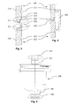
- FIG. 3 and FIG. 4 show a second embodiment of an inventive connection of a steel component with another enamelled steel component, before and after the inventive compound has been realized.
- An apparatus wall 201 made of steel as an enamelled steel component has a connection region 210, which in turn comprises an enameled region 211 and a non-enameled region 212.
- the connection region 210 further includes a crack 214 where the solder may flow during a brazing operation.
- the apparatus wall 201 further has an enamelled inner side 216 and a groove 217. The enamelled inner side 216 is continuously connected to the enamelled region 211 of the connection region 210.
- a further apparatus wall 202 made of steel as a further enamelled steel component has a connection region 210, which in turn comprises an enamelled region 221 and a non-enameled region 222.
- the further apparatus wall 202 further has an enamelled inner side 226 and a groove 227.
- the enamelled inner side 226 is continuously connected to the enamelled region 221 of the connecting region 220.
- the apparatus wall 201 and the further apparatus wall 202 are joined together and locked with an axial securing device 204, which is inserted into the groove 217, 227 of the apparatus wall 201 and the further apparatus wall 202. Subsequently is carried out with a heat source and the supply of solder, the brazing process and thereby the respective enamelled region 211, 221 connected directly cohesively and the respective non-enamelled region 212, 222 directly bonded cohesively. After the brazing process, the heat source and the axial fuse 204 are removed.
- FIG. 5 shows an embodiment of an apparatus 300 with apparatus nozzle 301.
- the respective apparatus nozzle 301 has a connecting portion 310 which is connected to a pipe part 1 (see Fig. 1 ) can be materially connected according to the inventive method.
Landscapes
- Engineering & Computer Science (AREA)
- General Engineering & Computer Science (AREA)
- Mechanical Engineering (AREA)
- Chemical & Material Sciences (AREA)
- Ceramic Engineering (AREA)
- Branch Pipes, Bends, And The Like (AREA)
Applications Claiming Priority (1)
| Application Number | Priority Date | Filing Date | Title |
|---|---|---|---|
| CH00722/09A CH701028A2 (de) | 2009-05-08 | 2009-05-08 | Verfahren für die stoffschlüssige Verbindung zweier emaillierter Stahlbauteile und entsprechende stoffschlüssige Verbindung. |
Publications (1)
| Publication Number | Publication Date |
|---|---|
| EP2248620A1 true EP2248620A1 (fr) | 2010-11-10 |
Family
ID=42629544
Family Applications (1)
| Application Number | Title | Priority Date | Filing Date |
|---|---|---|---|
| EP10405095A Withdrawn EP2248620A1 (fr) | 2009-05-08 | 2010-05-05 | Liaison par fusion de deux composants an acier émaillés |
Country Status (2)
| Country | Link |
|---|---|
| EP (1) | EP2248620A1 (fr) |
| CH (1) | CH701028A2 (fr) |
Cited By (1)
| Publication number | Priority date | Publication date | Assignee | Title |
|---|---|---|---|---|
| EP4006473A1 (fr) * | 2020-11-25 | 2022-06-01 | Lu-Ve S.P.A. | Dispositif de protection et de renfort pour tuyaux d'échangeur de chaleur et échangeur de chaleur doté de ce dispositif |
Citations (4)
| Publication number | Priority date | Publication date | Assignee | Title |
|---|---|---|---|---|
| US2540052A (en) * | 1945-06-20 | 1951-01-30 | Republic Industries | Porcelain enameled tank |
| FR1151186A (fr) * | 1956-06-04 | 1958-01-24 | Bitumes Speciaux | Procédé de protection, contre la corrosion, des extrémités des tubes en acier destinés à être joints par soudure |
| US2888783A (en) * | 1953-02-12 | 1959-06-02 | Frederick W Turnbull | Mold for applying enamel |
| RU2344910C1 (ru) * | 2007-09-03 | 2009-01-27 | Государственное образовательное учреждение высшего профессионального образования Томский политехнический университет | Способ сварки эмалированных труб с внутренней защитой сварного стыка |
-
2009
- 2009-05-08 CH CH00722/09A patent/CH701028A2/de not_active Application Discontinuation
-
2010
- 2010-05-05 EP EP10405095A patent/EP2248620A1/fr not_active Withdrawn
Patent Citations (4)
| Publication number | Priority date | Publication date | Assignee | Title |
|---|---|---|---|---|
| US2540052A (en) * | 1945-06-20 | 1951-01-30 | Republic Industries | Porcelain enameled tank |
| US2888783A (en) * | 1953-02-12 | 1959-06-02 | Frederick W Turnbull | Mold for applying enamel |
| FR1151186A (fr) * | 1956-06-04 | 1958-01-24 | Bitumes Speciaux | Procédé de protection, contre la corrosion, des extrémités des tubes en acier destinés à être joints par soudure |
| RU2344910C1 (ru) * | 2007-09-03 | 2009-01-27 | Государственное образовательное учреждение высшего профессионального образования Томский политехнический университет | Способ сварки эмалированных труб с внутренней защитой сварного стыка |
Cited By (1)
| Publication number | Priority date | Publication date | Assignee | Title |
|---|---|---|---|---|
| EP4006473A1 (fr) * | 2020-11-25 | 2022-06-01 | Lu-Ve S.P.A. | Dispositif de protection et de renfort pour tuyaux d'échangeur de chaleur et échangeur de chaleur doté de ce dispositif |
Also Published As
| Publication number | Publication date |
|---|---|
| CH701028A2 (de) | 2010-11-15 |
Similar Documents
| Publication | Publication Date | Title |
|---|---|---|
| EP2899100B1 (fr) | Liaison adhésive et procédé d'adhésion de deux profilés | |
| EP2372330B1 (fr) | Détecteur de bulles | |
| DE1908888A1 (de) | Rohrverbindung und Verfahren zu ihrer Herstellung | |
| EP3347605B1 (fr) | Procédé de fabrication d'un échangeur de chaleur | |
| DE1138869B (de) | Verfahren zur Herstellung einer Halbleiteranordnung | |
| DE102020204492A1 (de) | Flüssigkeitsleitung mit einem Kunststoff-Wellschlauch | |
| DE202008001101U1 (de) | Schweißsystem für mehrschichtige Verbundrohre aus Kunststoff und Metall | |
| DE19914061A1 (de) | Anschlußelement für Verbundschläuche und Verfahren zum Anschließen von Verbundschläuchen | |
| EP3458821B1 (fr) | Procédé de fabrication d'un système de transmetteur de pression | |
| EP2248620A1 (fr) | Liaison par fusion de deux composants an acier émaillés | |
| DE102011004729A1 (de) | Keramische Druckmesszelle und Drucksensor mit keramischer Druckmesszelle | |
| DE3008153A1 (de) | Anordnung zum verschweissen von rohren o.ae. hohlkoerpern unter einsatz einer schutzgasatmosphaere im bereich der schweissnaht | |
| DE1627483A1 (de) | Verfahren zur Verbindung plattierter Rohre durch Schweissen ohne Auftragsmetall | |
| DE2707539C2 (de) | Rohrleitungsverteiler | |
| EP3587110A2 (fr) | Ensemble de tuyauterie métallique pourvu de pièce de raccordement fabriquée de manière générative | |
| EP3298316B1 (fr) | Raccord à brides pour éléments en matière plastique, en particulier pour éléments tubulaires en matière plastique | |
| DE202008013039U1 (de) | Medienverteilerrohr für eine Chlorelektrolyse-Anlage | |
| EP0322500B1 (fr) | Bride pour tuyaux avec un tuyau de raccordement pour une tuyère de sprinkler | |
| DE102009024126A1 (de) | Bauteil mit Flansch sowie Verfahren zum Zusammenfügen derselben | |
| EP0056834B1 (fr) | Procédé de fabrication d'un module comprenant un élément chauffant tubulaire | |
| DE102017210086B4 (de) | Anschlussvorrichtung | |
| WO2021156278A1 (fr) | Procédé de fabrication d'une conduite hydraulique haute-pression, et également presse radiale pour mettre en œuvre le procédé | |
| DE4231823C2 (de) | Prozeßanschlußflansch für Druckmeßaufnehmer | |
| DE202014100755U1 (de) | Haltevorrichtung zum Halten von Rohren, die zum Transportieren von Fluiden verwendet werden | |
| DE102014106927A1 (de) | Messgerät, insbesondere Durchflussmessgerät, und Verfahren zur zur Herstellung eines Messrohres für ein Messgerät |
Legal Events
| Date | Code | Title | Description |
|---|---|---|---|
| PUAI | Public reference made under article 153(3) epc to a published international application that has entered the european phase |
Free format text: ORIGINAL CODE: 0009012 |
|
| AK | Designated contracting states |
Kind code of ref document: A1 Designated state(s): AL AT BE BG CH CY CZ DE DK EE ES FI FR GB GR HR HU IE IS IT LI LT LU LV MC MK MT NL NO PL PT RO SE SI SK SM TR |
|
| AX | Request for extension of the european patent |
Extension state: BA ME RS |
|
| STAA | Information on the status of an ep patent application or granted ep patent |
Free format text: STATUS: THE APPLICATION IS DEEMED TO BE WITHDRAWN |
|
| 18D | Application deemed to be withdrawn |
Effective date: 20110511 |