EP2248730A1 - Kleincontainer - Google Patents
Kleincontainer Download PDFInfo
- Publication number
- EP2248730A1 EP2248730A1 EP10007289A EP10007289A EP2248730A1 EP 2248730 A1 EP2248730 A1 EP 2248730A1 EP 10007289 A EP10007289 A EP 10007289A EP 10007289 A EP10007289 A EP 10007289A EP 2248730 A1 EP2248730 A1 EP 2248730A1
- Authority
- EP
- European Patent Office
- Prior art keywords
- container
- wall
- small container
- frame
- heating
- Prior art date
- Legal status (The legal status is an assumption and is not a legal conclusion. Google has not performed a legal analysis and makes no representation as to the accuracy of the status listed.)
- Granted
Links
- 238000001816 cooling Methods 0.000 claims abstract description 21
- 230000001681 protective effect Effects 0.000 claims abstract description 5
- 229910001220 stainless steel Inorganic materials 0.000 claims abstract description 5
- 239000010935 stainless steel Substances 0.000 claims abstract description 5
- 238000010438 heat treatment Methods 0.000 claims description 22
- 238000004049 embossing Methods 0.000 claims description 4
- 210000004907 gland Anatomy 0.000 claims 2
- 238000009413 insulation Methods 0.000 description 6
- 239000000463 material Substances 0.000 description 5
- 238000004519 manufacturing process Methods 0.000 description 3
- 239000013585 weight reducing agent Substances 0.000 description 3
- 238000010276 construction Methods 0.000 description 2
- 239000011810 insulating material Substances 0.000 description 2
- 229910052751 metal Inorganic materials 0.000 description 2
- 239000002184 metal Substances 0.000 description 2
- 229910000831 Steel Inorganic materials 0.000 description 1
- 229910052782 aluminium Inorganic materials 0.000 description 1
- XAGFODPZIPBFFR-UHFFFAOYSA-N aluminium Chemical compound [Al] XAGFODPZIPBFFR-UHFFFAOYSA-N 0.000 description 1
- 238000004880 explosion Methods 0.000 description 1
- 230000002349 favourable effect Effects 0.000 description 1
- 239000011888 foil Substances 0.000 description 1
- 231100001261 hazardous Toxicity 0.000 description 1
- 230000000977 initiatory effect Effects 0.000 description 1
- 239000007788 liquid Substances 0.000 description 1
- 238000002310 reflectometry Methods 0.000 description 1
- 230000003014 reinforcing effect Effects 0.000 description 1
- 230000008439 repair process Effects 0.000 description 1
- 239000010959 steel Substances 0.000 description 1
- 230000007704 transition Effects 0.000 description 1
Images


Classifications
-
- B—PERFORMING OPERATIONS; TRANSPORTING
- B65—CONVEYING; PACKING; STORING; HANDLING THIN OR FILAMENTARY MATERIAL
- B65D—CONTAINERS FOR STORAGE OR TRANSPORT OF ARTICLES OR MATERIALS, e.g. BAGS, BARRELS, BOTTLES, BOXES, CANS, CARTONS, CRATES, DRUMS, JARS, TANKS, HOPPERS, FORWARDING CONTAINERS; ACCESSORIES, CLOSURES, OR FITTINGS THEREFOR; PACKAGING ELEMENTS; PACKAGES
- B65D81/00—Containers, packaging elements, or packages, for contents presenting particular transport or storage problems, or adapted to be used for non-packaging purposes after removal of contents
- B65D81/38—Containers, packaging elements, or packages, for contents presenting particular transport or storage problems, or adapted to be used for non-packaging purposes after removal of contents with thermal insulation
- B65D81/3802—Containers, packaging elements, or packages, for contents presenting particular transport or storage problems, or adapted to be used for non-packaging purposes after removal of contents with thermal insulation rigid container in the form of a barrel or vat
- B65D81/3811—Containers, packaging elements, or packages, for contents presenting particular transport or storage problems, or adapted to be used for non-packaging purposes after removal of contents with thermal insulation rigid container in the form of a barrel or vat formed of different materials, e.g. laminated or foam filling between walls
-
- B—PERFORMING OPERATIONS; TRANSPORTING
- B65—CONVEYING; PACKING; STORING; HANDLING THIN OR FILAMENTARY MATERIAL
- B65D—CONTAINERS FOR STORAGE OR TRANSPORT OF ARTICLES OR MATERIALS, e.g. BAGS, BARRELS, BOTTLES, BOXES, CANS, CARTONS, CRATES, DRUMS, JARS, TANKS, HOPPERS, FORWARDING CONTAINERS; ACCESSORIES, CLOSURES, OR FITTINGS THEREFOR; PACKAGING ELEMENTS; PACKAGES
- B65D7/00—Containers having bodies formed by interconnecting or uniting two or more rigid, or substantially rigid, components made wholly or mainly of metal
- B65D7/02—Containers having bodies formed by interconnecting or uniting two or more rigid, or substantially rigid, components made wholly or mainly of metal characterised by shape
- B65D7/04—Containers having bodies formed by interconnecting or uniting two or more rigid, or substantially rigid, components made wholly or mainly of metal characterised by shape of curved cross-section, e.g. cans of circular or elliptical cross-section
- B65D7/045—Casks, barrels, or drums in their entirety, e.g. beer barrels, i.e. presenting most of the following features like rolling beads, double walls, reinforcing and supporting beads for end walls
-
- B—PERFORMING OPERATIONS; TRANSPORTING
- B65—CONVEYING; PACKING; STORING; HANDLING THIN OR FILAMENTARY MATERIAL
- B65D—CONTAINERS FOR STORAGE OR TRANSPORT OF ARTICLES OR MATERIALS, e.g. BAGS, BARRELS, BOTTLES, BOXES, CANS, CARTONS, CRATES, DRUMS, JARS, TANKS, HOPPERS, FORWARDING CONTAINERS; ACCESSORIES, CLOSURES, OR FITTINGS THEREFOR; PACKAGING ELEMENTS; PACKAGES
- B65D77/00—Packages formed by enclosing articles or materials in preformed containers, e.g. boxes, cartons, sacks or bags
- B65D77/04—Articles or materials enclosed in two or more containers disposed one within another
- B65D77/0446—Articles or materials enclosed in two or more containers disposed one within another the inner and outer containers being rigid or semi-rigid and the outer container being of polygonal cross-section not formed by folding or erecting one or more blanks
- B65D77/0453—Articles or materials enclosed in two or more containers disposed one within another the inner and outer containers being rigid or semi-rigid and the outer container being of polygonal cross-section not formed by folding or erecting one or more blanks the inner container having a polygonal cross-section
- B65D77/0466—Articles or materials enclosed in two or more containers disposed one within another the inner and outer containers being rigid or semi-rigid and the outer container being of polygonal cross-section not formed by folding or erecting one or more blanks the inner container having a polygonal cross-section the containers being mounted on a pallet
Definitions
- the invention relates to a small container according to the preamble of patent claim 1.
- Such Kleincontainer are for example from the DE 200 13 000 known. They have a container or tank, which is used in a frame with a standardized floor plan, which usually allows the stacking of several small container.
- cooling or heating devices for example consisting of cooling or heating coils, which are controlled by a corresponding control device, are often mounted on the outside of the container.
- an outer sheath is usually provided, which can be attached to the outside of the frame or prefabricated together with the container as a mounting unit and, for example, consists of sheet metal. Insulating means are usually arranged between the container and the outer jacket in order to increase the efficiency of the cooling or heating. Since the outer jacket is exposed to all external influences, in particular also impacts and collisions with other objects, it is understood that it must be made sufficiently stable in order to survive these unscathed.
- the object of the invention is to provide a small container with low production and transport costs.
- the small container according to the invention arranged in a frame, by an insulating layer thermally insulated container, wherein at least one wall of the container is designed as a double wall with an inner wall and an outer wall, wherein the insulating layer between the inner wall and the outer Wall of the double wall is arranged and / or in which the frame has a base frame, a support on the container stacking frame and supports.
- the invention is based on the finding that, with a suitable embodiment, the container wall can assume a plurality of tasks.
- the container wall can accommodate a part of the forces acting on the frame forces when they are introduced into the wall, so that the frame only has to be designed to accommodate lesser loads, what also brings tangible savings in terms of material and weight.
- a heating or cooling device is additionally provided, so that the desired temperature in the small container can be selectively controlled.
- the heating or cooling device on one or more mounted outside the container controls and arranged between the inner wall and the outer wall heating or cooling coils.
- the heating or cooling device may in particular also have one or more heating or cooling circuits.
- control has a stainless steel protective housing and / or is installed in a pressure-sealed housing and the outer wall is penetrated by at least one cable feedthrough, which is preferably liquid-tight and / or gas-tight, since such small container for applications, in which they must be explosion proof, can be used.
- cable bushings made of stainless steel, which are welded circumferentially to the outer wall of the container.
- a particularly cost-effective production of Kleincontainers is possible if the wall of the container is made of segments together, which are welded together.
- segments which are welded together.
- an embodiment with three segments, namely a subfloor, a jacket and a topsoil has proven to be in which the subfloor and the jacket and the topsoil and the jacket are welded together.
- the subfloor can significantly contribute to the complete emptying of the container is possible. This structuring can be achieved very inexpensively and simply by deep drawing.
- a particularly stable arrangement of the container in the frame can be achieved if the inner wall of the container is supported on the base frame. This is advantageously done with round tube feet, the number of which can be limited to three in order to save weight.
- the distance between inner wall and outer wall is at least in sections not constant. This makes it possible in particular to make the shape of the outer wall as simple as possible even in areas where the inner wall is structured. This also contributes to the cost reduction.
- FIG. 1 shows a cross section through a small container 10 according to the invention. It can be seen a frame composed of supports 11, base frame 12 and stack frame 13 and a container 14.
- the wall of the container 14 is composed of three sections, namely an underbody 15, a shell 16 and a top 17.
- the underbody 15, shell 16 and upper floor 17 are each double-walled and each have an inner wall 15.1, 16.1, 17.1 and an outer wall 15.2, 16.2, 17.2.
- an insulating layer 15.3, 16.3, 17.3 is arranged, which is formed in the simplest case as a cavity or space between opposite wall sections.
- the upper floor 17 passes through to fill the container 14, a manhole 18, which is closable with a lid 19.
- the lid 19 may be designed for example as a screw cap or clamping ring cover.
- the underbody 15 passes through a container outlet 20, which can be closed by means of a butterfly valve 21 or a Kugelhans.
- the inner wall 15.1 of the subfloor 15 has at least in sections a slope in the direction of the container outlet 20, which supports the emptying of contents.
- the outer wall 15.2 of the subfloor 15 has a cylindrical embossment 22 which engages with a centering plate 23 provided in the base frame 12 and so ensures the optimal centering of the container 14 in the base frame 12.
- FIG. 1 Next is the sectional view of FIG. 1 to take a Rundrohrfuß 24, which supports the inner wall 15.1 of the subfloor 15 on the base frame 12.
- the area B which is defined by a circular boundary line in FIG. 1 is marked, defines the in FIG. 2a enlarged section of the illustrated FIG. 1 ,
- FIG. 2a shows an enlarged view of the in FIG. 1 With this area, a portion of a support 11, a base frame 12, a bottom 15 and a shell 16 can be seen, with sub-bottom 15 or shell 16 each have an inner wall 15.1 and 16.1 and an outer wall 15.2 or 16.2.
- FIG. 2a can be seen that in the double wall of the subfloor 15 and the shell 16 embedded insulating 15.3 and 16.3, the thickness of which is not constant at least in sections, where "sections not constant" both differences between different areas of Kleincontainerwandung, eg upper floor 17 and shell 16, as well as differences within a range of the Kleachintainerwandung, eg within the subfloor 15 includes.
- the jacket 16 in general, the jacket 16 a thinner insulation layer 16.3 than the subfloor 15, while on the other hand, a variation of the thickness of the insulating material 15.3 is given at different points of the subfloor 15.
- the area E which is defined by a circular boundary line in FIG. 2a is marked, defines the in FIG. 2b enlarged section of the illustrated FIG. 2a ,
- FIG. 2b shows an enlarged view of the in FIG. 2a area marked with the letter E.
- a transition between an underbody 15 with inner wall 15.1 and outer wall 15.2 and a shell 16 with inner wall 16.1 and outer wall 16.2 can be seen in detail.
- the inner wall 15.1 of the subfloor 15 in the contact region has a higher wall thickness than the inner wall 16.1 of the shell 16. It has been found that such a variation of the wall thickness is tolerable in weld joints as long as the material offset of the components not is more than 50%. This finding is therefore of considerable relevance for weight reduction, as the minimum wall thickness required in the ADR / RID / IMGD Code must be fulfilled in each area of the container wall.
- the subfloor 15 is usually structured, which in particular in the advantageous structuring by deep drawing in certain sections, but not at the edge of the subfloor 15, which is welded to the jacket 16, to a Thickness reduction leads. This edge thus has a greater thickness than is absolutely necessary. Without the provision of a difference in wall thicknesses of underbody 15 and shell 16 in their contact area, therefore, the jacket 16 would have to be made stronger than required, which would entail considerable weight disadvantages.
- FIG. 3a shows an exemplary embodiment the inner wall 15.1 of a subfloor 15 of the small container 10 from FIG. 1 with an outflow opening 300. Especially in the FIG. 3a shaded areas reduces the wall thickness by up to 0.7 mm.
- FIG. 3b is an enlargement of the in FIG. 3a shown area around the outflow opening 300, but now viewed from the outside, to illustrate the areas of reduced wall thickness even clearer.
- FIG. 4 the small container 10 off FIG. 1 with partially removed outer wall 15.2, 16.2, 17.2 and transparent insulation layer 15.3, 16.3, 17.3 shown.
- outer wall 15.2, 16.2, 17.2 and transparent insulation layer 15.3, 16.3, 17.3 in addition to supports 11, base frame 12 stack frame 13 and container 14, only inner walls 15.1, 16.1, 17.1 of the double wall of the container 14.
- an aluminum foil not shown, are arranged, whose reflectivity increases the efficiency of use, especially of heating coils 401 noticeably.
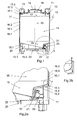
- FIG. 5 shows a side view of the FIG. 1 In this illustration, one recognizes further a protective housing 501, in the interior of which the control for the heating or cooling is arranged.
- FIG. 6 shows the view of FIG. 1 known Kleincontainers 10 obliquely from below.
- the base frame 12 with the centering plate 23, in which the cylindrical embossment 22 is received in the bottom 15, can be particularly well recognized.
- FIG. 7 shows the view of FIG. 1 known Kleincontainers 10 obliquely from above.
- the stack frame 13 engages the edges of the top 17 at least partially the stack frame 13, which has two longitudinal profiles 701, 702 and two transverse profiles 703, 704.
- the longitudinal or transverse profiles 701, 702 and 703, 704 are preferably angle profiles, with an angle profile in particular two straight metal strips, in each case one of the longitudinal edges of the one strip are connected at right angles to one of the longitudinal edges of the other strip to understand.
- forces introduced into the frame are in part transmitted to the edge sections of the upper floor 17 engaging under the angle profiles.
- catch shoes 706 are advantageously provided on the stack frame 13, in which protuberances of the base frame 12 or feet of another, similar small container 10 can engage. This prevents unwanted shifting stacked small container 10 relative to each other.
- the area A which is defined by a circular boundary line in FIG. 7 is marked, defines the in FIG. 8 enlarged shown Detail of the FIG. 7 , a corner of the stack frame 13.
- FIG. 8 shows a detailed view of the section A from FIG. 7 , which in particular provides further information about the structure of the stacking frame 13.
- FIG. 9 1 shows a cable feedthrough 900 through an outer wall 901 of a small container 10, with which a heating cable 902 and a sensor line 903 are welded by means of a V2A screw connection 904 which is peripherally welded to the outer wall 901.
- the cable bushing 900 designed for liquid and gas tightness, which in particular allows use in accordance with ATEX in hazardous areas Ex II G EEx ed (ib) II C T4, if in addition the protective housing of the heating or cooling control is pressure-encapsulated.
- FIG. 10 summarizes in tabular form the weight savings for a typical small container 10, broken down by the individual measures.
Landscapes
- Engineering & Computer Science (AREA)
- Mechanical Engineering (AREA)
- Filling Or Discharging Of Gas Storage Vessels (AREA)
Abstract
Description
- Die Erfindung betrifft einen Kleincontainer gemäß dem Oberbegriff des Patentanspruchs 1.
- Derartige Kleincontainer sind beispielsweise aus der
DE 200 13 000 bekannt. Sie besitzen einen Behälter oder Tank, der in einem Gestell mit genormtem Grundriss eingesetzt ist, das in der Regel das Aufeinanderstapeln mehrerer Kleincontainer erlaubt. Insbesondere beim Einsatz im Lebensmittelbereich sind auf der Außenseite des Behälters oftmals Kühl- oder Beheizungseinrichtungen, z.B. bestehend aus Kühl- oder Heizschlangen angebracht, die von einer entsprechenden Steuereinrichtung geregelt werden. Um diese Kühl- oder Beheizungseinrichtungen zu schützen, ist in der Regel ein Außenmantel vorgesehen, der außen am Gestell angebracht oder gemeinsam mit dem Behälter als Montageeinheit vorgefertigt sein kann und beispielsweise aus Blech besteht. Zwischen Behälter und Außenmantel sind meist Isoliermittel angeordnet, um die Effizienz der Kühlung bzw. Heizung zu erhöhen. Da der Außenmantel frei allen äußeren Einflüssen, insbesondere auch Stößen und Kollisionen mit anderen Objekten ausgesetzt ist, versteht es sich, dass er hinreichend stabil ausgeführt sein muss, um diese unbeschadet zu überstehen. - Bei der Konstruktion solcher Kleincontainer sind strenge Regeln zu beachten, die im ADR/RID/IMGD-Code, dort insbesondere im Kapitel 6.5, zusammengefasst sind. Beispielsweise finden sich dort Regelungen, die eine Mindestwanddicke des Behälters, bezogen auf einen Referenzstahl, festschreiben. Dies führt einerseits zu einem hohen Materialaufwand, also hohen Herstellungskosten und andererseits zu einem hohen Gewicht, also hohen Transportkosten.
- Aufgabe der Erfindung ist es, einen Kleincontainer mit günstigen Herstellungs- und Transportkosten bereitzustellen.
- Diese Aufgabe wird gelöst durch einen Kleincontainer mit den Merkmalen des Patentanspruchs 1.
- Somit weist der erfindungsgemäße Kleincontainer einen in einem Gestell angeordneten, durch eine Isolationsschicht thermisch isolierten Behälter, auf, bei dem mindestens eine Wandung des Behälters als Doppelwandung mit einer inneren Wand und einer äußeren Wand ausgeführt ist, wobei die Isolationsschicht zwischen der inneren Wand und der äußeren Wand der Doppelwandung angeordnet ist und/oder bei dem das Gestell einen Grundrahmen, einen sich auf dem Behälter abstützenden Stapelrahmen und Stützen aufweist.
- Der Erfindung liegt die Erkenntnis zu Grunde, dass bei geeigneter Ausgestaltung die Behälterwandung mehrere Aufgaben übernehmen kann.
- So kann einerseits durch Ausführung der Behälterwandung als Doppelwandung mit eingelagerter Isolierschicht bei gleichzeitiger Wahrung der Sicherheitsvorschriften die Funktion des bisher verwendeten separaten Außenmantels übernommen werden, wodurch dieser entfallen kann, was zu erheblicher Material- und Gewichtsersparnis führt.
- Alternativ oder zusätzlich kann die Behälterwandung einen Teil der auf das Gestell wirkenden Kräfte aufnehmen, wenn diese in die Wandung eingeleitet werden, so dass das Gestell nur noch für die Aufnahme geringerer Lasten ausgelegt sein muss, was ebenfalls spürbare Einsparungen hinsichtlich Material und Gewicht mit sich bringt.
- In einer bevorzugten Variante der Erfindung ist zusätzlich eine Heiz- oder Kühlvorrichtung vorgesehen, so dass die gewünschte Temperatur im Kleincontainer gezielt ansteuerbar ist. Dabei weist die Heiz- oder Kühlvorrichtung eine oder mehrere außerhalb des Behälters angebrachte Steuerungen und zwischen der inneren Wand und der äußeren Wand angeordnete Heiz- oder Kühlschlangen auf. Die Heiz- oder Kühlvorrichtung kann insbesondere auch ein oder mehrere Heiz- oder Kühlkreisläufe aufweisen.
- Besonders vorteilhaft ist weiterhin, wenn die Steuerung ein Edelstahl-Schutzgehäuse aufweist und/oder in einem druckgekapselten Gehäuse eingebaut ist und die äußere Wand von mindestens einer Kabeldurchführung durchsetzt ist, die vorzugsweise flüssigkeitsdicht und/oder gasdicht ausgeführt ist, da derartige Kleincontainer für Anwendungen, in denen sie explosionsgeschützt sein müssen, einsetzbar sind. Besonders geeignet für solche Anwendungen sind Kabeldurchführungen aus Edelstahl, die umlaufend mit der äußeren Wand des Behälters verschweißt sind.
- Eine besonders kostengünstige Herstellung des Kleincontainers ist möglich, wenn die Wandung des Behälters aus aus Segmenten zusammen gesetzt ist, die miteinander verschweißt sind. Insbesondere hat sich eine Ausführungsform mit drei Segmenten, nämlich einem Unterboden, einem Mantel und einen Oberboden bewährt, bei der der Unterboden und der Mantel sowie der Oberboden und der Mantel miteinander verschweißt sind.
- Der Unterboden kann durch seine Struktur wesentlich dazu beitragen, dass eine möglichst vollständige Entleerung des Behälters möglich ist. Diese Strukturierung kann sehr kostengünstig und einfach durch Tiefziehen erreicht werden.
- Versieht man weiter den Grundrahmen mit einem Zentrierteller und den Unterboden mit einer zylindrischen Prägung, wird das Zusammensetzen von Gestell und Behälter, das beispielsweise zur Erstmontage oder bei Reparaturen notwendig ist, wesentlich vereinfacht.
- Eine besonders einfache Einleitung von auf das Gestell wirkenden Kräften in den Behälter ist möglich, wenn der Stapelrahmen zumindest in Bereichen, in denen er sich auf dem Behälter abstützt, ein Winkelprofil aufweist.
- Weitere Gewichtsvorteile sind erzielbar, wenn die Stützen des Gestells als Hohlprofile gefertigt sind.
- Eine besonders stabile Anordnung des Behälters im Gestell kann erreicht werden, wenn die innere Wand des Behälters auf dem Grundrahmen abgestützt ist. Dies geschieht vorteilhafterweise mit Rundrohrfüßen, wobei deren Zahl auf drei beschränkt werden kann, um Gewicht zu sparen.
- Besonders vorteilhaft ist es, wenn bei der Doppelwandung der Abstand zwischen innerer Wand und äußerer Wand zumindest abschnittsweise nicht konstant ist. Dadurch ist es insbesondere möglich, die Form der äußeren Wand auch in solchen Bereichen möglichst einfach zu gestalten, in denen die innere Wand strukturiert ausgeführt ist. Dies trägt ebenfalls zur Kostensenkung bei.
- Im Folgenden werden spezielle Ausführungsformen der Erfindung anhand der beigefügten Figuren näher erläutert.
- Es zeigt
- Fig. 1:
- einen Querschnitt durch einen erfindungsgemäßen Kleincontainer,
- Fig. 2a:
- einen vergrößerten Ausschnitt aus
Figur 1 , - Fig. 2b:
- einen vergrößerten Ausschnitt aus
Figur 2a , - Fig. 3a:
- die innere Wand eines Unterbodens des Kleincontainer aus
Figur 1 , betrachtet von schräg oben, - Fig. 3b:
- einen Ausschnitt aus der in
Figur 3a gezeigten inne- ren Wand, betrachtet von außen, - Fig. 4:
- eine Seitenansicht des Kleincontainers aus
Figur 1 , wobei äußere Wände und Isoliermaterial als transpa- rent angenommen sind, - Fig. 5:
- eine Seitenansicht des Kleincontainers aus
Figur 1 , - Fig. 6:
- eine Ansicht des Kleincontainers aus
Figur 1 , be- trachtet von schräg unten, - Fig. 7:
- eine Ansicht des Kleincontainers aus
Figur 1 , be- trachtet von schräg oben, - Fig. 8:
- eine Ausschnittsvergrößerung eines Details der
Figur 7 , - Fig. 9:
- eine Kabeldurchführung durch eine äußere Wand eines Kleincontainers und
- Fig.10:
- eine Tabelle, in der an einem konkreten Beispiel die erzielbare Gewichtsreduktion verdeutlicht wird.
- Gleiche Objekte werden in allen Figuren mit gleichen Bezugsziffern bezeichnet, sofern nichts anderes erwähnt ist.
-
Figur 1 zeigt einen Querschnitt durch einen erfindungsgemäßen Kleincontainer 10 . Man erkennt ein Gestell, zusammengesetzt aus Stützen 11, Grundrahmen 12 und Stapelrahmen 13 und einen Behälter 14. Die Wandung des Behälters 14 ist aus drei Abschnitten, nämlich einem Unterboden 15, einem Mantel 16 und einem Oberboden 17 zusammengesetzt. In der dargestellten Ausführungsform sind Unterboden 15, Mantel 16 und Oberboden 17 jeweils doppelwandig ausgeführt und weisen jeweils eine innere Wand 15.1, 16.1, 17.1 und eine äußere Wand 15.2, 16.2, 17.2 auf. Zwischen der inneren Wand 15.1, 16.1, 17.1 und der äußeren Wand 15.2, 16.2, 17.2 ist im dargestellten Ausführungsbeispiel jeweils eine Isolationsschicht 15.3, 16.3, 17.3 angeordnet, die im einfachsten Fall als Hohlraum oder Zwischenraum zwischen gegenüberliegenden Wandabschnitten gebildet ist. - Den Oberboden 17 durchsetzt zur Befüllung des Behälters 14 ein Mannloch 18, das mit einem Deckel 19 verschließbar ist. Der Deckel 19 kann beispielsweise als Schraubdeckel oder Spannringdeckel ausgeführt sein. Den Unterboden 15 durchsetzt ein Behälterauslauf 20, der mittels einer Absperrklappe 21 oder eines Kugelhans verschließbar ist. Die innere Wand 15.1 des Unterbodens 15 weist zumindest abschnittsweise ein Gefälle in Richtung auf den Behälterauslauf 20 auf, das die Entleerung von Füllgut unterstützt. Die äußere Wand 15.2 des Unterbodens 15 weist eine zylindrische Prägung 22 auf, die mit einem im Grundrahmen 12 vorgesehen Zentrierteller 23 im Eingriff steht und so die optimale Zentrierung des Behälters 14 im Grundrahmen 12 sicherstellt.
- Weiter ist der Schnittdarstellung der
Figur 1 ein Rundrohrfuß 24 zu entnehmen, der die innere Wand 15.1 des Unterbodens 15 am Grundrahmen 12 abstützt. - Der Bereich B, der durch eine kreisförmige Begrenzungslinie in
Figur 1 markiert ist, definiert den inFigur 2a vergrößert dargestellten Ausschnitt derFigur 1 . -
Figur 2a zeigt eine vergrößerte Darstellung des inFigur 1 mit dem Buchstaben B gekennzeichneten Bereichs, Dieser Darstellung sind ein Teil einer Stütze 11, eines Grundrahmens 12, eines Unterbodens 15 und eines Mantels 16 zu entnehmen, wobei Unter terboden 15 bzw. Mantel 16 jeweils eine innere Wand 15.1 bzw. 16.1 und eine äußere Wand 15.2 bzw. 16.2 aufweisen. - Ebenfalls in
Figur 2a zu erkennen ist das in der Doppelwandung des Unterbodens 15 bzw. des Mantels 16 eingelagerte Isoliermaterial 15.3 und 16.3, dessen Stärke zumindest abschnittsweise nicht konstant ist, wobei "abschnittsweise nicht konstant" sowohl Unterschiede zwischen unterschiedlichen Bereichen der Kleincontainerwandung, z.B. Oberboden 17 und Mantel 16, als auch Unterschiede innerhalb eines Bereiches der Kleincontainerwandung, z.B. innerhalb des Unterbodens 15, umfasst. - Konkret weist im Ausführungsbeispiel der
Figur 2a einerseits generell der Mantel 16 eine dünnere Isolationsschicht 16.3 auf als der Unterboden 15, während andererseits auch eine Variation der Stärke des Isoliermaterials 15.3 an unterschiedlichen Stellen des Unterbodens 15 gegeben ist. - Der Bereich E, der durch eine kreisförmige Begrenzungslinie in
Figur 2a markiert ist, definiert den inFigur 2b vergrößert dargestellten Ausschnitt derFigur 2a . -
Figur 2b zeigt eine vergrößerte Darstellung des inFigur 2a mit dem Buchstaben E gekennzeichneten Bereichs. In dieser Darstellung ist ein Übergang zwischen einem Unterboden 15 mit innerer Wand 15.1 und äußerer Wand 15.2 und einem Mantel 16 mit innerer Wand 16.1 und äußerer Wand 16.2 im Detail zu erkennen. - Insbesondere ist ersichtlich, dass die innere Wand 15.1 des Unterbodens 15 im Kontaktbereich eine höhere Wandstärke aufweist als die innere Wand 16.1 des Mantels 16. Es hat sich gezeigt, dass eine derartige Variation der Wandstärke bei Schweißnahtverbindungen solange tolerabel ist, wie der Materialversatz der Komponenten nicht mehr als 50% beträgt. Diese Erkenntnis ist zur Gewichtsreduktion deshalb von erheblicher Relevanz,.als die im ADR/RID/IMGD-Code geforderte Mindestwandstärke jeweils in jedem Bereich der Behälterwandung erfüllt sein muss. Um eine vollständige Entleerung des Kleincontainers 10 zu fördern, ist der Unterboden 15 in der Regel strukturiert, was insbesondere bei der vorteilhaften Strukturierung durch Tiefziehen in bestimmten Abschnitten, nicht aber an der Kante des Unterbodens 15, die mit dem Mantel 16 verschweißt wird, zu einer Wanddickenreduzierung führt. Diese Kante weist somit eine höhere Dicke als zwingend erforderlich ist auf. Ohne das Vorsehen eines Unterschiedes der Wandstärken von Unterboden 15 und Mantel 16 in ihrem Kontaktbereich müsste somit der Mantel 16 stärker als gefordert ausgeführt werden, was erhebliche Gewichtsnachteile mit sich brächte.
- Zur weiteren Veranschaulichung dieses Sachverhaltes dienen die
Figuren 3a und 3b. Figur 3a zeigt eine beispielhafte Ausgestaltung der inneren Wand 15.1 eines Unterbodens 15 des Kleincontainers 10 ausFigur 1 mit einer Ausflussöffnung 300. Besonders in den inFigur 3a schraffiert dargestellten Bereichen ist durch Tiefziehbearbeitung die Wanddicke reduziert, und zwar um bis zu 0,7 mm. InFigur 3b ist eine Vergrößerung des inFigur 3a gezeigten Bereichs um die Ausflussöffnung 300, jedoch nun von aussen betrachtet, dargestellt, um die Bereiche reduzierter Wanddicke noch klarer darzustellen. - Um den Aufbau des Kleincontainers 10 weiter zu verdeutlichen, ist in
Figur 4 der Kleincontainer 10 ausFigur 1 mit teilweise entfernter äußerer Wand 15.2, 16.2, 17.2 und transparenter Isolationsschicht 15.3, 16.3, 17.3 dargestellt. In dieser Darstellung erkennt man neben Stützen 11, Grundrahmen 12 Stapelrahmen 13 und Behälter 14, nur innere Wände 15.1, 16.1, 17.1 der Doppelwandung des Behälters 14. Zusätzlich sind Heiz- oder Kühlschlangen 401 sowie eine Zuleitung zu 402 zu den Heiz- oder Kühlschlangen zu erkennen. Gegebenenfalls kann zwischen den Heiz- oder Kühlschlangen 401 und der nicht dargestellten Isolationsschicht auch noch eine nicht dargestellte Aluminiumfolie angeordnet werden, deren Reflektivität die Nutzungseffizienz insbesondere von Heizschlangen 401 spürbar erhöht. - Weiter sind Darstellung des Kleincontainers 10 in
Figur 4 drei Rundrohrfüße 24 zu entnehmen, die die innere Wand 15.1 des Unterbodens 15 am Grundrahmen 12 abstützen. -
Figur 5 zeigt eine Seitenansicht des ausFigur 1 bekannten Kleincontainers 10. In dieser Darstellung erkennt man weiter ein Schutzgehäuse 501, in dessen Inneren die Steuerung für die Heizung oder Kühlung angeordnet ist. -
Figur 6 zeigt die Ansicht des ausFigur 1 bekannten Kleincontainers 10 von schräg unten. In dieser Perspektive lässt sich der Grundrahmen 12 mit dem Zentrierteller 23, in den die zylindrische Prägung 22 im Unterboden 15 aufgenommen ist, besonders gut erkennen. -
Figur 7 zeigt die Ansicht des ausFigur 1 bekannten Kleincontainers 10 von schräg oben. In dieser Darstellung ist besonders gut zu erkennen, wie die Einleitung von Stapelkräften in den Körper des Behälters 14 durch geeignete Auslegung des Stapelrahmens 13 erzielt werden kann. Wie aus dieser Figur ersichtlich ist, untergreifen die Kanten des Oberbodens 17 zumindest abschnittsweise den Stapelrahmen 13, der zwei Längsprofile 701, 702 und zwei Querprofile 703, 704 aufweist. Bei den Längs- bzw. Querprofilen 701, 702 bzw. 703, 704 handelt es sich vorzugsweise um Winkelprofile, wobei unter einem Winkelprofil insbesondere zwei gerade Metallstreifen, bei denen jeweils eine der Längskanten des einen Streifens rechtwinklig mit einer der Längskanten des anderen Streifens verbunden sind, zu verstehen sind. In das Gestell eingeleitete Kräfte werden somit zum Teil auf die die Winkelprofile untergreifenden Kantenabschnitte des Oberbodens 17 übertragen. Besonders günstig ist es, die Krafteinleitung über den Oberboden 17 zu verteilen, indem eine Verstärkungsstruktur, insbesondere eine Versteifungsprägung 705 vorgesehen ist. Ferner sind auf dem Stapelrahmen 13 vorteilhafterweise Fangschuhe 706 vorgesehen, in die Ausstülpungen des Grundrahmens 12 oder Füße eines weiteren, gleichartigen Kleincontainers 10 eingreifen können. Damit wird ein ungewolltes Verschieben gestapelter Kleincontainer 10 relativ zueinander verhindert. - Der Bereich A, der durch eine kreisförmige Begrenzungslinie in
Figur 7 markiert ist, definiert den inFigur 8 vergrößert dargestellten Ausschnitt derFigur 7 , eine Ecke des Stapelrahmens 13. -
Figur 8 zeigt eine Detailansicht des Ausschnitts A ausFigur 7 , der insbesondere weiteren Aufschluss über den Aufbau des Stapelrahmens 13 gibt. -
Figur 9 zeigt eine Kabeldurchführung 900 durch eine äußere Wand 901 eines Kleincontainers 10, mit der ein Heizkabel 902 und eine Fühlerleitung 903 durch eine V2A-Verschraubung 904, die mit der äußeren Wand 901 umlaufend verschweißt ist. Die wie inFigur 9 gestaltete Kabeldurchführung 900 sorgt für Flüssigkeits- und Gasdichtigkeit, was insbesondere den Einsatz gemäß ATEX im Ex-Bereich Ex II G EEx ed (ib) II C T4 ermöglicht, wenn zusätzlich das Schutzgehäuse der Heizungs- oder Kühlungssteuerung druckgekapselt ausgeführt ist. -
Figur 10 fasst tabellarisch die nach den einzelnen Maßnahmen aufgeschlüsselten Gewichtseinsparungen für einen typischen Kleincontainer 10 zusammen. Die durch das Doppelwandungsprinzip in Kombination mit der Einleitung eines Teils der wirkenden Kräfte in den Behälter führt ausweislich dieser Tabelle zu einer Gewichtsreduktion des Taragewichts des Behälters von über 15%; die Materialkosten skalieren ähnlich. - Die ausweislich der
Figur 10 erzielten Gewichtseinsparungen resultieren einerseits wesentlich daraus, dass durch die Auslegung der Behälterwandung als Doppelwandung die Innenwandung des Behälters bzw. Tanks dünner ausgeführt werden kann. Da hier Unterboden 15, Mantel 16 und Oberboden 17 alle mit Doppelwandung ausgeführt sind, sind bei all diesen Bauteilen Gewichtseinsparungen möglich. Daneben tritt, dass die Knickkräfte, für die das Gestell ausgelegt sein muss, durch partielles Einleiten der Stapelkräfte in den Behälter 14 -d.h. präziser formuliert in dessen Körper- reduziert werden. Dies erlaubt eine leichtere Bauform des Stapelrahmens 13 mit leichteren Längsprofilen 701, 702, Querprofilen 703, 704 und Fangschuhen 706 sowie der Stützen 11 und ferner das Vorsehen eines Rohrrahmens als Grundrahmen 12. -
- 10
- Kleincontainer
- 11
- Stütze
- 12
- Grundrahmen
- 13
- Stapelrahmen
- 14
- Behälter
- 15
- Unterboden
- 15.1
- innere Wand des Unterbodens
- 15.2
- äußere Wand des Unterbodens
- 15.3
- Isolationsschicht des Unterbodens
- 16
- Mantel
- 16.1
- innere Wand des Mantels
- 16.2
- äußere Wand des Mantels
- 16.3
- Isolationsschicht des Mantels
- 17
- Oberboden
- 17.1
- innere Wand des Oberbodens
- 17.2
- äußere Wand des Oberbodens
- 17.3
- Isolationsschicht des Oberbodens
- 18
- Mannloch
- 19
- Deckel
- 20
- Behälterauslauf
- 21
- Absperrklappe
- 22
- Zylindrische Prägung
- 23
- Zentrierteller
- 24
- Rundrohrfuß
- 300
- Ausflussöffnung
- 401
- Heiz- oder Kühlschlange
- 402
- Zuleitung
- 501
- Schutzgehäuse
- 701
- Längsprofil
- 702
- Längsprofil
- 703
- Querprofil
- 704
- Querprofil
- 705
- Versteifungsprägung
- 706
- Fangschuh
- 900
- Kabeldurchführung
- 901
- äußere Wand
- 902
- Heizleitung
- 903
- Fühlerleitung
- 904
- V2A-Verschraubung
- A
- Bereichskennzeichung
- B
- Bereichskennzeichung
- E
- Bereichskennzeichnung
Claims (12)
- Kleincontainer (10) mit einem in einem Gestell angeordneten, durch eine Isolationsschicht (15.3, 16.3, 17.3) thermisch isolierten Behälter (14),
dadurch gekennzeichnet, dass das Gestell einen Grundrahmen (12), einen Stapelrahmen (13) und Stützen (11) aufweist, wobei der Stapelrahmen (13) auf dem Behälter (14) abgestützt ist. - Kleincontainer (10) nach Anspruch 1,
dadurch gekennzeichnet, dass zusätzlich eine Heiz- oder Kühlvorrichtung mit ein oder mehreren Heiz-oder Kühlkreisläufen vorgesehen ist. - Kleincontainer (10) nach Anspruch 2,
dadurch gekennzeichnet, dass die Heiz-oder Kühlvorrichtung eine oder mehrere außerhalb des Behälters angebrachte Steuerungen und zwischen der inneren Wand und der äußeren Wand angeordnete Heiz- oder Kühlschlangen (401) aufweist. - Kleincontainer (10) nach Anspruch 3,
dadurch gekennzeichnet, dass die Steuerung ein druckgekapseltes Schutzgehäuse (501) aus Edelstahl aufweist oder in einem druckgekapselten Gehäuse (501) eingebaut ist. - Kleincontainer (10) nach Anspruch 3 oder 4,
dadurch gekennzeichnet, dass die äußere Wand von mindestens einer Kabeldurchführung (900) durchsetzt ist. - Kleincontainer (10) nach Anspruch 5,
dadurch gekennzeichnet, dass die Kabeldurchführung (900) flüssigkeitsdicht und/oder gasdicht ist. - Kleincontainer (10) nach Anspruch 5 oder 6,
dadurch gekennzeichnet, dass die Kabeldurchführung (900) aus Edelstahl ist. - Kleincontainer (10) nach einem vorstehenden Anspruch, dadurch gekennzeichnet, dass die Wandung des Behälters (14) aus einem Unterboden (15) , einem Mantel (16) und einen Oberboden (17) zusammengesetzt ist, wobei der Unterboden (15) und der Mantel (16) sowie der Oberboden (17) und der Mantel (16) miteinander verschweißt sind.
- Kleincontainer (10) nach Anspruch 8,
dadurch gekennzeichnet, dass der Unterboden (15) tiefgezogen ist. - Kleincontainer (10) nach einem vorstehenden Anspruch,
dadurch gekennzeichnet, dass der Grundrahmen (12) einen Zentrierteller (23) und der Unterboden (15) eine zylindrische Prägung (22) aufweisen. - Kleincontainer (10) nach einem vorstehenden Anspruch,
dadurch gekennzeichnet, dass der Stapelrahmen (13) zumindest in Bereichen, in denen er sich auf dem Behälter (14) abstützt, ein Winkelprofil aufweist. - Kleincontainer (10) nach einem vorstehenden Anspruch, dadurch gekennzeichnet, dass die Stützen (11) des Gestells als Hohlprofile gefertigt sind.
Priority Applications (1)
| Application Number | Priority Date | Filing Date | Title |
|---|---|---|---|
| EP10007289.1A EP2248730B1 (de) | 2008-02-14 | 2008-02-14 | Kleincontainer |
Applications Claiming Priority (2)
| Application Number | Priority Date | Filing Date | Title |
|---|---|---|---|
| EP10007289.1A EP2248730B1 (de) | 2008-02-14 | 2008-02-14 | Kleincontainer |
| EP20080002742 EP2090519B1 (de) | 2008-02-14 | 2008-02-14 | Kleincontainer |
Related Parent Applications (1)
| Application Number | Title | Priority Date | Filing Date |
|---|---|---|---|
| EP08002742.8 Division | 2008-02-14 |
Publications (2)
| Publication Number | Publication Date |
|---|---|
| EP2248730A1 true EP2248730A1 (de) | 2010-11-10 |
| EP2248730B1 EP2248730B1 (de) | 2013-05-29 |
Family
ID=39539708
Family Applications (2)
| Application Number | Title | Priority Date | Filing Date |
|---|---|---|---|
| EP10007289.1A Not-in-force EP2248730B1 (de) | 2008-02-14 | 2008-02-14 | Kleincontainer |
| EP20080002742 Not-in-force EP2090519B1 (de) | 2008-02-14 | 2008-02-14 | Kleincontainer |
Family Applications After (1)
| Application Number | Title | Priority Date | Filing Date |
|---|---|---|---|
| EP20080002742 Not-in-force EP2090519B1 (de) | 2008-02-14 | 2008-02-14 | Kleincontainer |
Country Status (2)
| Country | Link |
|---|---|
| EP (2) | EP2248730B1 (de) |
| DE (1) | DE202008017716U1 (de) |
Cited By (1)
| Publication number | Priority date | Publication date | Assignee | Title |
|---|---|---|---|---|
| CN105358446A (zh) * | 2013-07-04 | 2016-02-24 | 普罗特克纳有限公司 | 由塑料构成的内容器以及用于液体的具有这种内容器的运输和存放容器 |
Families Citing this family (5)
| Publication number | Priority date | Publication date | Assignee | Title |
|---|---|---|---|---|
| DE202011100484U1 (de) * | 2011-05-09 | 2012-08-10 | Ucon Ag Containersysteme Kg | Container mit Steuereinheit |
| CN103158928A (zh) * | 2011-12-09 | 2013-06-19 | 中国国际海运集装箱(集团)股份有限公司 | 容器的下封头及包括该下封头的容器 |
| RU2511570C1 (ru) * | 2012-12-24 | 2014-04-10 | Закрытое акционерное общество "АлтайСпецИзделия" | Способ монтажа системы обогрева двухстенных резервуаров |
| CN103587852B (zh) * | 2013-11-18 | 2015-12-02 | 常州市华戚热水供应站 | 车载保温罐 |
| CN110342106A (zh) * | 2019-07-02 | 2019-10-18 | 徐州明威饲料有限公司 | 一种兔饲料生产储存箱 |
Citations (7)
| Publication number | Priority date | Publication date | Assignee | Title |
|---|---|---|---|---|
| DE2734271A1 (de) * | 1977-07-29 | 1979-02-01 | Hoesch Werke Ag | Lager- und transporteinheit |
| DE3813433A1 (de) * | 1987-08-28 | 1989-03-09 | Bernd Buedenbender | Behaelter, insbesondere fass |
| US4882912A (en) * | 1988-10-12 | 1989-11-28 | Container Design Limited | Temperature controllable tank container |
| US4918927A (en) * | 1989-09-06 | 1990-04-24 | Harsco Corporation | Cryogenic liquid container |
| US5490603A (en) * | 1994-09-06 | 1996-02-13 | Snyder Industries, Inc. | Fluid tank apparatus |
| DE20013000U1 (de) | 2000-07-27 | 2000-10-05 | UCON AG Containersysteme KG, 77756 Hausach | Zylindrischer Kleincontainer |
| DE20008131U1 (de) * | 2000-05-05 | 2001-09-13 | Ernst Bohle GmbH, 51645 Gummersbach | Transportbehälter |
Family Cites Families (1)
| Publication number | Priority date | Publication date | Assignee | Title |
|---|---|---|---|---|
| DE8119693U1 (de) * | 1981-07-06 | 1986-03-27 | Bolz sen., Alfred, 7988 Wangen | Hoftank |
-
2008
- 2008-02-14 EP EP10007289.1A patent/EP2248730B1/de not_active Not-in-force
- 2008-02-14 EP EP20080002742 patent/EP2090519B1/de not_active Not-in-force
- 2008-02-14 DE DE200820017716 patent/DE202008017716U1/de not_active Expired - Lifetime
Patent Citations (7)
| Publication number | Priority date | Publication date | Assignee | Title |
|---|---|---|---|---|
| DE2734271A1 (de) * | 1977-07-29 | 1979-02-01 | Hoesch Werke Ag | Lager- und transporteinheit |
| DE3813433A1 (de) * | 1987-08-28 | 1989-03-09 | Bernd Buedenbender | Behaelter, insbesondere fass |
| US4882912A (en) * | 1988-10-12 | 1989-11-28 | Container Design Limited | Temperature controllable tank container |
| US4918927A (en) * | 1989-09-06 | 1990-04-24 | Harsco Corporation | Cryogenic liquid container |
| US5490603A (en) * | 1994-09-06 | 1996-02-13 | Snyder Industries, Inc. | Fluid tank apparatus |
| DE20008131U1 (de) * | 2000-05-05 | 2001-09-13 | Ernst Bohle GmbH, 51645 Gummersbach | Transportbehälter |
| DE20013000U1 (de) | 2000-07-27 | 2000-10-05 | UCON AG Containersysteme KG, 77756 Hausach | Zylindrischer Kleincontainer |
Cited By (3)
| Publication number | Priority date | Publication date | Assignee | Title |
|---|---|---|---|---|
| CN105358446A (zh) * | 2013-07-04 | 2016-02-24 | 普罗特克纳有限公司 | 由塑料构成的内容器以及用于液体的具有这种内容器的运输和存放容器 |
| CN105358446B (zh) * | 2013-07-04 | 2018-04-17 | 普罗特克纳有限公司 | 由塑料构成的内容器以及用于液体的具有这种内容器的运输和存放容器 |
| US10773871B2 (en) | 2013-07-04 | 2020-09-15 | Protechna S.A. | Inner container made of plastic and transport and storage container for liquids comprising such an inner container |
Also Published As
| Publication number | Publication date |
|---|---|
| EP2090519B1 (de) | 2013-04-10 |
| EP2090519A1 (de) | 2009-08-19 |
| DE202008017716U1 (de) | 2010-04-08 |
| EP2248730B1 (de) | 2013-05-29 |
Similar Documents
| Publication | Publication Date | Title |
|---|---|---|
| EP2090519B1 (de) | Kleincontainer | |
| DE102015110244B4 (de) | Batteriezellengehäuse und Verfahren zu dessen Herstellung | |
| DE102006018639A1 (de) | Von einem Außenbehälter umgebener und zur Aufnahme einer kryogenen Flüssigkeit dienender Innenbehälter | |
| DE3137083A1 (de) | Kugelfoermiger behaelter oder kammer | |
| DE2456379A1 (de) | Druckbehaelter, insbesondere kernreaktordruckbehaelter | |
| CH622850A5 (de) | ||
| EP2085326B1 (de) | Verfahren zum Herstellen eines Kunststoff-Tanks und Kunststoff-Tank | |
| EP1895223B1 (de) | Rohrelement für Abwasser- und Entwässerungsleitungen mit einer Revisionsöffnung | |
| AT391301B (de) | Brauchwasserspeicher | |
| DE29513656U1 (de) | Thermisch isolierter Tank- oder Silobehälter | |
| DE60003041T3 (de) | Lebensmittelbehälter | |
| DE202004021811U1 (de) | Schichtenspeicher mit einem Gehäuse und einer Isolierung | |
| DE1958365A1 (de) | Druckbehaelter | |
| DE102018113115B3 (de) | Transport- und Lagerbehälter für Flüssigkeiten | |
| AT407145B (de) | Behälter, insbesondere dose | |
| EP2975614B1 (de) | Transport- und/oder Lagerbehälter, Montagevorrichtung und Verfahren zum Verschließen eines Transport- und/oder Lagerbehälters | |
| EP3050822B1 (de) | Behälter, tankcontaineranordnung | |
| DE102006012025A1 (de) | Flüssigkeitsbehälter und Herstellungsverfahren | |
| DE202007018273U1 (de) | Behälter | |
| AT518760B1 (de) | Leckschutzfolie für einen Fluidtank | |
| EP4402398A1 (de) | Kryobehälter mit einer im vakuumraum geführten leitung | |
| DE19527139A1 (de) | Verfahren zur Herstellung von doppelwandigen Bauteilen, insbesondere für doppelwandige Behälter und mit diesem Verfahren hergestelltes Bauteil | |
| EP0691277B1 (de) | Stapelbarer Behälter | |
| DE202018001789U1 (de) | Doppelwandige Ladungsträgersystemkomponente | |
| DE2128209A1 (de) | Fluessigkeits-, insbesondere oelbehaelter |
Legal Events
| Date | Code | Title | Description |
|---|---|---|---|
| PUAI | Public reference made under article 153(3) epc to a published international application that has entered the european phase |
Free format text: ORIGINAL CODE: 0009012 |
|
| AC | Divisional application: reference to earlier application |
Ref document number: 2090519 Country of ref document: EP Kind code of ref document: P |
|
| AK | Designated contracting states |
Kind code of ref document: A1 Designated state(s): AT BE BG CH CY CZ DE DK EE ES FI FR GB GR HR HU IE IS IT LI LT LU LV MC MT NL NO PL PT RO SE SI SK TR |
|
| 17P | Request for examination filed |
Effective date: 20110201 |
|
| 17Q | First examination report despatched |
Effective date: 20110915 |
|
| GRAP | Despatch of communication of intention to grant a patent |
Free format text: ORIGINAL CODE: EPIDOSNIGR1 |
|
| GRAS | Grant fee paid |
Free format text: ORIGINAL CODE: EPIDOSNIGR3 |
|
| GRAA | (expected) grant |
Free format text: ORIGINAL CODE: 0009210 |
|
| AC | Divisional application: reference to earlier application |
Ref document number: 2090519 Country of ref document: EP Kind code of ref document: P |
|
| AK | Designated contracting states |
Kind code of ref document: B1 Designated state(s): AT BE BG CH CY CZ DE DK EE ES FI FR GB GR HR HU IE IS IT LI LT LU LV MC MT NL NO PL PT RO SE SI SK TR |
|
| REG | Reference to a national code |
Ref country code: GB Ref legal event code: FG4D Free format text: NOT ENGLISH |
|
| REG | Reference to a national code |
Ref country code: CH Ref legal event code: NV Representative=s name: R. A. EGLI AND CO. PATENTANWAELTE, CH Ref country code: CH Ref legal event code: EP |
|
| REG | Reference to a national code |
Ref country code: AT Ref legal event code: REF Ref document number: 614232 Country of ref document: AT Kind code of ref document: T Effective date: 20130615 |
|
| REG | Reference to a national code |
Ref country code: IE Ref legal event code: FG4D Free format text: LANGUAGE OF EP DOCUMENT: GERMAN |
|
| REG | Reference to a national code |
Ref country code: DE Ref legal event code: R096 Ref document number: 502008010045 Country of ref document: DE Effective date: 20130725 |
|
| REG | Reference to a national code |
Ref country code: LT Ref legal event code: MG4D |
|
| PG25 | Lapsed in a contracting state [announced via postgrant information from national office to epo] |
Ref country code: IS Free format text: LAPSE BECAUSE OF FAILURE TO SUBMIT A TRANSLATION OF THE DESCRIPTION OR TO PAY THE FEE WITHIN THE PRESCRIBED TIME-LIMIT Effective date: 20130929 Ref country code: SE Free format text: LAPSE BECAUSE OF FAILURE TO SUBMIT A TRANSLATION OF THE DESCRIPTION OR TO PAY THE FEE WITHIN THE PRESCRIBED TIME-LIMIT Effective date: 20130529 Ref country code: NO Free format text: LAPSE BECAUSE OF FAILURE TO SUBMIT A TRANSLATION OF THE DESCRIPTION OR TO PAY THE FEE WITHIN THE PRESCRIBED TIME-LIMIT Effective date: 20130829 Ref country code: PT Free format text: LAPSE BECAUSE OF FAILURE TO SUBMIT A TRANSLATION OF THE DESCRIPTION OR TO PAY THE FEE WITHIN THE PRESCRIBED TIME-LIMIT Effective date: 20130930 Ref country code: ES Free format text: LAPSE BECAUSE OF FAILURE TO SUBMIT A TRANSLATION OF THE DESCRIPTION OR TO PAY THE FEE WITHIN THE PRESCRIBED TIME-LIMIT Effective date: 20130909 Ref country code: LT Free format text: LAPSE BECAUSE OF FAILURE TO SUBMIT A TRANSLATION OF THE DESCRIPTION OR TO PAY THE FEE WITHIN THE PRESCRIBED TIME-LIMIT Effective date: 20130529 Ref country code: SI Free format text: LAPSE BECAUSE OF FAILURE TO SUBMIT A TRANSLATION OF THE DESCRIPTION OR TO PAY THE FEE WITHIN THE PRESCRIBED TIME-LIMIT Effective date: 20130529 Ref country code: GR Free format text: LAPSE BECAUSE OF FAILURE TO SUBMIT A TRANSLATION OF THE DESCRIPTION OR TO PAY THE FEE WITHIN THE PRESCRIBED TIME-LIMIT Effective date: 20130830 |
|
| REG | Reference to a national code |
Ref country code: NL Ref legal event code: VDEP Effective date: 20130529 |
|
| PG25 | Lapsed in a contracting state [announced via postgrant information from national office to epo] |
Ref country code: HR Free format text: LAPSE BECAUSE OF FAILURE TO SUBMIT A TRANSLATION OF THE DESCRIPTION OR TO PAY THE FEE WITHIN THE PRESCRIBED TIME-LIMIT Effective date: 20130529 Ref country code: PL Free format text: LAPSE BECAUSE OF FAILURE TO SUBMIT A TRANSLATION OF THE DESCRIPTION OR TO PAY THE FEE WITHIN THE PRESCRIBED TIME-LIMIT Effective date: 20130529 Ref country code: BG Free format text: LAPSE BECAUSE OF FAILURE TO SUBMIT A TRANSLATION OF THE DESCRIPTION OR TO PAY THE FEE WITHIN THE PRESCRIBED TIME-LIMIT Effective date: 20130829 |
|
| PG25 | Lapsed in a contracting state [announced via postgrant information from national office to epo] |
Ref country code: LV Free format text: LAPSE BECAUSE OF FAILURE TO SUBMIT A TRANSLATION OF THE DESCRIPTION OR TO PAY THE FEE WITHIN THE PRESCRIBED TIME-LIMIT Effective date: 20130529 |
|
| PG25 | Lapsed in a contracting state [announced via postgrant information from national office to epo] |
Ref country code: SK Free format text: LAPSE BECAUSE OF FAILURE TO SUBMIT A TRANSLATION OF THE DESCRIPTION OR TO PAY THE FEE WITHIN THE PRESCRIBED TIME-LIMIT Effective date: 20130529 Ref country code: EE Free format text: LAPSE BECAUSE OF FAILURE TO SUBMIT A TRANSLATION OF THE DESCRIPTION OR TO PAY THE FEE WITHIN THE PRESCRIBED TIME-LIMIT Effective date: 20130529 Ref country code: DK Free format text: LAPSE BECAUSE OF FAILURE TO SUBMIT A TRANSLATION OF THE DESCRIPTION OR TO PAY THE FEE WITHIN THE PRESCRIBED TIME-LIMIT Effective date: 20130529 |
|
| PG25 | Lapsed in a contracting state [announced via postgrant information from national office to epo] |
Ref country code: RO Free format text: LAPSE BECAUSE OF FAILURE TO SUBMIT A TRANSLATION OF THE DESCRIPTION OR TO PAY THE FEE WITHIN THE PRESCRIBED TIME-LIMIT Effective date: 20130529 Ref country code: NL Free format text: LAPSE BECAUSE OF FAILURE TO SUBMIT A TRANSLATION OF THE DESCRIPTION OR TO PAY THE FEE WITHIN THE PRESCRIBED TIME-LIMIT Effective date: 20130529 |
|
| PLBE | No opposition filed within time limit |
Free format text: ORIGINAL CODE: 0009261 |
|
| STAA | Information on the status of an ep patent application or granted ep patent |
Free format text: STATUS: NO OPPOSITION FILED WITHIN TIME LIMIT |
|
| PGFP | Annual fee paid to national office [announced via postgrant information from national office to epo] |
Ref country code: CH Payment date: 20140220 Year of fee payment: 7 |
|
| 26N | No opposition filed |
Effective date: 20140303 |
|
| REG | Reference to a national code |
Ref country code: DE Ref legal event code: R097 Ref document number: 502008010045 Country of ref document: DE Effective date: 20140303 |
|
| PGFP | Annual fee paid to national office [announced via postgrant information from national office to epo] |
Ref country code: GB Payment date: 20140220 Year of fee payment: 7 |
|
| BERE | Be: lapsed |
Owner name: UCON A.G. CONTAINERSYSTEME KG Effective date: 20140228 |
|
| PG25 | Lapsed in a contracting state [announced via postgrant information from national office to epo] |
Ref country code: LU Free format text: LAPSE BECAUSE OF FAILURE TO SUBMIT A TRANSLATION OF THE DESCRIPTION OR TO PAY THE FEE WITHIN THE PRESCRIBED TIME-LIMIT Effective date: 20140214 Ref country code: MC Free format text: LAPSE BECAUSE OF FAILURE TO SUBMIT A TRANSLATION OF THE DESCRIPTION OR TO PAY THE FEE WITHIN THE PRESCRIBED TIME-LIMIT Effective date: 20130529 |
|
| REG | Reference to a national code |
Ref country code: IE Ref legal event code: MM4A |
|
| PG25 | Lapsed in a contracting state [announced via postgrant information from national office to epo] |
Ref country code: IE Free format text: LAPSE BECAUSE OF NON-PAYMENT OF DUE FEES Effective date: 20140214 Ref country code: BE Free format text: LAPSE BECAUSE OF NON-PAYMENT OF DUE FEES Effective date: 20140228 |
|
| REG | Reference to a national code |
Ref country code: CH Ref legal event code: PL |
|
| GBPC | Gb: european patent ceased through non-payment of renewal fee |
Effective date: 20150214 |
|
| PG25 | Lapsed in a contracting state [announced via postgrant information from national office to epo] |
Ref country code: LI Free format text: LAPSE BECAUSE OF NON-PAYMENT OF DUE FEES Effective date: 20150228 Ref country code: CH Free format text: LAPSE BECAUSE OF NON-PAYMENT OF DUE FEES Effective date: 20150228 |
|
| PG25 | Lapsed in a contracting state [announced via postgrant information from national office to epo] |
Ref country code: GB Free format text: LAPSE BECAUSE OF NON-PAYMENT OF DUE FEES Effective date: 20150214 |
|
| REG | Reference to a national code |
Ref country code: FR Ref legal event code: PLFP Year of fee payment: 9 |
|
| PG25 | Lapsed in a contracting state [announced via postgrant information from national office to epo] |
Ref country code: MT Free format text: LAPSE BECAUSE OF FAILURE TO SUBMIT A TRANSLATION OF THE DESCRIPTION OR TO PAY THE FEE WITHIN THE PRESCRIBED TIME-LIMIT Effective date: 20130529 |
|
| PG25 | Lapsed in a contracting state [announced via postgrant information from national office to epo] |
Ref country code: CY Free format text: LAPSE BECAUSE OF FAILURE TO SUBMIT A TRANSLATION OF THE DESCRIPTION OR TO PAY THE FEE WITHIN THE PRESCRIBED TIME-LIMIT Effective date: 20130529 |
|
| PG25 | Lapsed in a contracting state [announced via postgrant information from national office to epo] |
Ref country code: HU Free format text: LAPSE BECAUSE OF FAILURE TO SUBMIT A TRANSLATION OF THE DESCRIPTION OR TO PAY THE FEE WITHIN THE PRESCRIBED TIME-LIMIT; INVALID AB INITIO Effective date: 20080214 Ref country code: TR Free format text: LAPSE BECAUSE OF FAILURE TO SUBMIT A TRANSLATION OF THE DESCRIPTION OR TO PAY THE FEE WITHIN THE PRESCRIBED TIME-LIMIT Effective date: 20130529 |
|
| REG | Reference to a national code |
Ref country code: FR Ref legal event code: PLFP Year of fee payment: 10 |
|
| REG | Reference to a national code |
Ref country code: FR Ref legal event code: PLFP Year of fee payment: 11 |
|
| PGFP | Annual fee paid to national office [announced via postgrant information from national office to epo] |
Ref country code: CZ Payment date: 20190213 Year of fee payment: 12 Ref country code: FI Payment date: 20190211 Year of fee payment: 12 Ref country code: DE Payment date: 20190212 Year of fee payment: 12 Ref country code: IT Payment date: 20190226 Year of fee payment: 12 |
|
| PGFP | Annual fee paid to national office [announced via postgrant information from national office to epo] |
Ref country code: FR Payment date: 20190213 Year of fee payment: 12 Ref country code: AT Payment date: 20190211 Year of fee payment: 12 |
|
| REG | Reference to a national code |
Ref country code: DE Ref legal event code: R119 Ref document number: 502008010045 Country of ref document: DE |
|
| REG | Reference to a national code |
Ref country code: FI Ref legal event code: MAE |
|
| REG | Reference to a national code |
Ref country code: AT Ref legal event code: MM01 Ref document number: 614232 Country of ref document: AT Kind code of ref document: T Effective date: 20200214 |
|
| PG25 | Lapsed in a contracting state [announced via postgrant information from national office to epo] |
Ref country code: FI Free format text: LAPSE BECAUSE OF NON-PAYMENT OF DUE FEES Effective date: 20200214 Ref country code: CZ Free format text: LAPSE BECAUSE OF NON-PAYMENT OF DUE FEES Effective date: 20200214 |
|
| PG25 | Lapsed in a contracting state [announced via postgrant information from national office to epo] |
Ref country code: AT Free format text: LAPSE BECAUSE OF NON-PAYMENT OF DUE FEES Effective date: 20200214 |
|
| PG25 | Lapsed in a contracting state [announced via postgrant information from national office to epo] |
Ref country code: DE Free format text: LAPSE BECAUSE OF NON-PAYMENT OF DUE FEES Effective date: 20200901 Ref country code: FR Free format text: LAPSE BECAUSE OF NON-PAYMENT OF DUE FEES Effective date: 20200229 |
|
| PG25 | Lapsed in a contracting state [announced via postgrant information from national office to epo] |
Ref country code: IT Free format text: LAPSE BECAUSE OF NON-PAYMENT OF DUE FEES Effective date: 20200214 |