EP2248741B1 - Liaison d'une chaîne latérale pour courroies de transport - Google Patents
Liaison d'une chaîne latérale pour courroies de transport Download PDFInfo
- Publication number
- EP2248741B1 EP2248741B1 EP10161884A EP10161884A EP2248741B1 EP 2248741 B1 EP2248741 B1 EP 2248741B1 EP 10161884 A EP10161884 A EP 10161884A EP 10161884 A EP10161884 A EP 10161884A EP 2248741 B1 EP2248741 B1 EP 2248741B1
- Authority
- EP
- European Patent Office
- Prior art keywords
- link
- rod
- conveyor belt
- end part
- belt
- Prior art date
- Legal status (The legal status is an assumption and is not a legal conclusion. Google has not performed a legal analysis and makes no representation as to the accuracy of the status listed.)
- Active
Links
Images


Classifications
-
- B—PERFORMING OPERATIONS; TRANSPORTING
- B65—CONVEYING; PACKING; STORING; HANDLING THIN OR FILAMENTARY MATERIAL
- B65G—TRANSPORT OR STORAGE DEVICES, e.g. CONVEYORS FOR LOADING OR TIPPING, SHOP CONVEYOR SYSTEMS OR PNEUMATIC TUBE CONVEYORS
- B65G17/00—Conveyors having an endless traction element, e.g. a chain, transmitting movement to a continuous or substantially-continuous load-carrying surface or to a series of individual load-carriers; Endless-chain conveyors in which the chains form the load-carrying surface
- B65G17/06—Conveyors having an endless traction element, e.g. a chain, transmitting movement to a continuous or substantially-continuous load-carrying surface or to a series of individual load-carriers; Endless-chain conveyors in which the chains form the load-carrying surface having a load-carrying surface formed by a series of interconnected, e.g. longitudinal, links, plates, or platforms
- B65G17/063—Conveyors having an endless traction element, e.g. a chain, transmitting movement to a continuous or substantially-continuous load-carrying surface or to a series of individual load-carriers; Endless-chain conveyors in which the chains form the load-carrying surface having a load-carrying surface formed by a series of interconnected, e.g. longitudinal, links, plates, or platforms the load carrying surface being formed by profiles, rods, bars, rollers or the like attached to more than one traction element
- B65G17/064—Conveyors having an endless traction element, e.g. a chain, transmitting movement to a continuous or substantially-continuous load-carrying surface or to a series of individual load-carriers; Endless-chain conveyors in which the chains form the load-carrying surface having a load-carrying surface formed by a series of interconnected, e.g. longitudinal, links, plates, or platforms the load carrying surface being formed by profiles, rods, bars, rollers or the like attached to more than one traction element the profiles, rods, bars, rollers or the like being interconnected by a mesh or grid-like structure
-
- B—PERFORMING OPERATIONS; TRANSPORTING
- B65—CONVEYING; PACKING; STORING; HANDLING THIN OR FILAMENTARY MATERIAL
- B65G—TRANSPORT OR STORAGE DEVICES, e.g. CONVEYORS FOR LOADING OR TIPPING, SHOP CONVEYOR SYSTEMS OR PNEUMATIC TUBE CONVEYORS
- B65G17/00—Conveyors having an endless traction element, e.g. a chain, transmitting movement to a continuous or substantially-continuous load-carrying surface or to a series of individual load-carriers; Endless-chain conveyors in which the chains form the load-carrying surface
- B65G17/06—Conveyors having an endless traction element, e.g. a chain, transmitting movement to a continuous or substantially-continuous load-carrying surface or to a series of individual load-carriers; Endless-chain conveyors in which the chains form the load-carrying surface having a load-carrying surface formed by a series of interconnected, e.g. longitudinal, links, plates, or platforms
- B65G17/08—Conveyors having an endless traction element, e.g. a chain, transmitting movement to a continuous or substantially-continuous load-carrying surface or to a series of individual load-carriers; Endless-chain conveyors in which the chains form the load-carrying surface having a load-carrying surface formed by a series of interconnected, e.g. longitudinal, links, plates, or platforms the surface being formed by the traction element
- B65G17/086—Conveyors having an endless traction element, e.g. a chain, transmitting movement to a continuous or substantially-continuous load-carrying surface or to a series of individual load-carriers; Endless-chain conveyors in which the chains form the load-carrying surface having a load-carrying surface formed by a series of interconnected, e.g. longitudinal, links, plates, or platforms the surface being formed by the traction element specially adapted to follow a curved path
-
- B—PERFORMING OPERATIONS; TRANSPORTING
- B65—CONVEYING; PACKING; STORING; HANDLING THIN OR FILAMENTARY MATERIAL
- B65G—TRANSPORT OR STORAGE DEVICES, e.g. CONVEYORS FOR LOADING OR TIPPING, SHOP CONVEYOR SYSTEMS OR PNEUMATIC TUBE CONVEYORS
- B65G2201/00—Indexing codes relating to handling devices, e.g. conveyors, characterised by the type of product or load being conveyed or handled
- B65G2201/02—Articles
- B65G2201/0202—Agricultural and processed food products
Definitions
- the present invention relates to a link of a side chain for conveyor belts, according to the preamble of claim 1.
- Links of side chain for conveyor belts, particularly for food, are currently known which are constituted by a substantially U-shaped body made of metal plate in which the front portion is shaped so as to fit between the two facing end parts of the rear portion of a facing identical link.
- the front portion has two symmetrical and longitudinally extended slots for the passage and translational motion of an end portion of a rod-like element of the conveyor belt to which the chain link belongs.
- the rear portion has, on each end part, a hole for the insertion of an end portion of an additional rod-like element.
- the external rear end part has a lateral tab that is contoured for engagement with a wheel or belt provided with teeth of associated driving means.
- this external lateral tab is constituted by a flap of metal plate which is folded and extends from the rear edge of the external end part and again to the rear beyond such rear edge.
- An L-shaped tipping preventing element is then typically associated from the side of the link that is directed toward the conveyor belt and its horizontal portion is designed to slide below a guide of the conveyor belt.
- the thrust generated by the tooth of the wheel or belt provided with teeth produces a torque between the region of contact between the tooth and the tab and the region of contact of the tipping preventing shoulder with the corresponding guide, and such torque tends to impose a momentary rotation to the rod-like element of the belt that is jointly connected to the actuated link.
- the sequential occurrence of these events determines the characteristic oscillation of the rod-like elements that compose the belt at the driving means, an oscillation which can lead to unwanted stress on the conveyed food product.
- US 2005/067259 A1 discloses a link of a conveyor chain having a combination of features as set forth in the pre-characterizing portion of the appended claim 1.
- the aim of the present invention is to provide a link of a side chain for conveyor belts that improves the smoothness of the transmission of motion from the driving means to the belt, thus improving the stability of the conveyed products and ensuring greater integrity thereof.
- an object of the invention is to provide a link of a side chain for conveyor belts that is simple to provide, like known types of link.
- Another object of the invention is to provide a link that is also capable of speeding up the assembly of the conveyor belt to which it belongs.
- a further object of the invention is to provide a link that allows to provide conveyor belts that can be guided upward or downward with guiding toothed wheels that have a smaller diameter than the known art, with a significant improvement in the quality of the transfer of small products.
- Another object of the invention is to provide a link that allows to form a chain that can be driven by means of toothed wheels laterally, from above and from below with known types of driving means.
- Another object of the invention is to provide a link of a side chain for conveyor belts that is structurally simple, is easy to use, and can be manufactured with low costs with known systems and technologies.
- a link of a side chain for conveyor belts, particularly for food, is generally designated by the reference numeral 10 , which is visible in Figures 1, 2 and 3 .
- the link 10 is of the type that comprises a substantially V-shaped body 11, with the front portion 12 shaped so as to fit between the two facing end parts 13 and 14 of the rear portion 15 of an identical link 10a arranged in front.
- the front portion 12 has two longitudinally elongated symmetrical slots 16 and 17 for the passage and translational motion of an end portion 18 of a rod-like element 19 of a conveyor belt 20.
- the rear portion 15 has, on each end part 13 and 14, a hole, respectively 21 and 22, for the insertion of an end portion 18a of an additional rod-like element 19a, as exemplified in Figure 3 .
- the outer rear end part 13 has a lateral tab 23 that is contoured to mesh with a toothed wheel 24, but it might be a toothed belt, of associated driving means, of a per se known type, which are not shown for the sake of simplicity.
- the lateral tab 23 is formed, on the outer rear end part 13, so that it is crossed by the axis of the holes 25 for the rod-like element 19a.
- a tipping preventing shoulder 26 extends from the lower edge of the outer rear end part 13 and is designed to slide below a corresponding guide, which is to be understood as known, is not shown for the sake of simplicity and is associated with the conveyor belt 20.
- the link 10 is made of metal plate.
- the lateral tab 23 is provided by a flap 27 of metal plate, which extends from the outer end part 13 and is folded externally in a C-shaped configuration and so as to affect the axis 25 of the holes 21 and 22, as clearly shown in Figures 1 and 2 .
- tipping preventing shoulder 26 which is incorporated in the link 10, allows to save a component to be assembled.
- tipping preventing shoulder being formed on the outer rear end part 13 at, and very close to, the lateral tab 23, is such that, when the lateral tab 23 interacts with a tooth of the toothed wheel 24 of the driving means, the thrust generated by the tooth of the toothed wheel, which might likewise also be a toothed belt, produces no torque between the region of contact between the tooth and the tab and the region of contact of the tipping preventing shoulder 26 with its guide, or a torque that is very modest with respect to what can be obtained with known links, with the corresponding guide.
- the link according to the invention illustrated in particular in Figures 4 and 5 and designated therein by the reference numeral 110, is provided monolithically and made of plastics.
- the lateral tab 123 extends toward the outside of the outer end part 113 and has a seat 130 for the rapid engagement of a complementarily shaped end 131 of a rod-like element 119 of the conveyor belt 120.
- the seat 130 is open laterally onto the outside of the tab 123 and has protruding edges 132 for the snap engagement of the L-folded end 131 of a rod-like element 119.
- the link 110 thus allows to provide a conveyor belt 120 with rod-like elements that have both ends 131 folded into an L-shaped configuration for engagement with the corresponding seats 130 on the lateral tabs 123, as shown in Figure 6 , or a similar conveyor belt whose rod-like elements 119 have a single L-folded end 131, as shown in Figure 7 , since it is sufficient in practice to fix just one of the two ends of the rod-like element in order to stabilize its position also with respect to the opposite associated link 110.
- the belt 120 is much faster and cheaper to provide.
- the front portion 112 has two slots 116 and 117, which are the lateral ports of a single through opening that is formed transversely to the front portion 112.
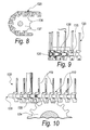
- the tip 135 of the front portion 112 of the V-shaped body 111 has a profile shaped substantially like involutes of a circle, so as to better interact with the teeth 136 of a toothed wheel 137 for guiding the conveyor belt 120 upward, as shown in Figures 8 and 9 , or downward.
- the particular shaping of the V-shaped body 111 also allows to provide conveyor belts 120 in which the diameter of the guiding wheels is smaller than in similar belts with links of the known type, thus improving the transfer of small products from the belt 122 to another belt or to another subsequent platform.
- the link 110 allows to provide chains 128 which can be driven easily either by means of a lateral toothed belt or wheel 124 or by means of a toothed belt or wheel 138 arranged above or below the chain 128.
- the link 110 has, on the inner face of the inner rear end part 114, a C-shaped seat 140 for the engagement of an end of a second rod-like element to be arranged laterally parallel to the first element 119 to provide a conveyor belt with a double number of rod-like elements.
- the fitting of a second bar can be performed easily, conveniently and quickly even if the belt 120 is already assembled.
- the present invention provides a link for a side strain for conveyor belts that improves the smoothness of the transmission of motion from the driving means to the belt, thus improving stability and ensuring greater integrity of the conveyed products.
- the invention provides a link of a side chain for conveyor belts that is simple to provide, for example made of metallic plate, like links of the known type.
- the invention provides a link that is also capable of providing swifter assembly of the conveyor belt to which it belongs, for example in the embodiment made of plastics exemplified above, which is provided with a seat for rapid snap engagement of a contoured end of an associated rod-like element of the belt.
- the invention provides a link that allows to provide conveyor belts that can be guided upward or downward with guiding toothed wheels that have a smaller diameter than the known art, with a significant improvement in the quality of the transfer of small products.
- the link according to the invention further allows to define a chain that can be driven by means of toothed wheels laterally, from above and from below with known types of driving means.
- the present invention provides a link of a side chain for conveyor belts that is structurally simple, easy to use, and can be manufactured at low costs with known systems and technologies.
- the materials used may be any according to requirements and to the state of the art.
Landscapes
- Engineering & Computer Science (AREA)
- Mechanical Engineering (AREA)
- Chain Conveyers (AREA)
- Devices For Conveying Motion By Means Of Endless Flexible Members (AREA)
Claims (3)
- Maillon (110) d'une chaîne latérale pour les courroies transporteuses, en particulier celles destinées aux produits alimentaires, du type comprenant un corps essentiellement en forme de V (111), avec la partie avant (112) mise en forme de manière à s'ajuster entre les deux parties d'extrémité opposées (113, 114) de la partie arrière (115) d'un maillon identique agencé en avant, ladite partie avant ayant deux fentes symétriques (116, 117) longitudinalement allongées pour permettre le passage et le mouvement de translation d'une partie d'extrémité d'un élément en forme de tige (119) d'une courroie transporteuse (120), ladite partie arrière (115) ayant, sur chacune desdites parties d'extrémité (113, 114), un trou pour l'insertion d'une partie d'extrémité d'un élément en forme de tige supplémentaire, la partie (113) d'extrémité arrière extérieure ayant une languette latérale (123) qui est profilée de manière à s'engrener avec une roue ou une courroie pourvue de dents d'un moyen d'entraînement associé, ladite languette latérale (123) étant formée, sur ladite partie (113) d'extrémité arrière extérieure, de sorte qu'elle soit traversée par l'axe des trous pour ledit élément en forme de tige (119), ledit maillon étant réalisé de manière monolithique en matière plastique, et ladite languette latérale (123) s'étendant vers l'extérieur de ladite partie d'extrémité extérieure (113) et ayant un siège (130) pour l'engagement rapide d'une extrémité de forme complémentaire (131) d'un élément en forme de tige (119) de la courroie transporteuse (120), le maillon étant caractérisé en ce que ledit siège (130) est ouvert latéralement sur l'extérieur de ladite languette (123) et a des bords en saillie (132) pour l'engagement par encliquetage de l'extrémité pliée en L (131) d'un élément en forme de tige (119).
- Maillon selon la revendication 1, caractérisé en ce qu'une pointe (135) de la partie avant (112) du corps en forme de V (111) présente un profil essentiellement en forme de développantes d'un cercle.
- Maillon selon la revendication 1, caractérisé en ce qu'il comporte, sur la face interne de la partie (114) d'extrémité arrière intérieure, un siège en forme de C (140) pour l'engagement d'une extrémité d'un deuxième élément en forme de tige devant être disposé latéralement en étant adjacent et parallèle au premier élément en forme de tige (119), pour fournir une courroie transporteuse ayant un nombre double d'éléments en forme de tige.
Applications Claiming Priority (1)
| Application Number | Priority Date | Filing Date | Title |
|---|---|---|---|
| ITPD2009A000126A IT1394088B1 (it) | 2009-05-08 | 2009-05-08 | Maglia per catena laterale per nastri trasportatori |
Publications (2)
| Publication Number | Publication Date |
|---|---|
| EP2248741A1 EP2248741A1 (fr) | 2010-11-10 |
| EP2248741B1 true EP2248741B1 (fr) | 2012-10-24 |
Family
ID=41508395
Family Applications (1)
| Application Number | Title | Priority Date | Filing Date |
|---|---|---|---|
| EP10161884A Active EP2248741B1 (fr) | 2009-05-08 | 2010-05-04 | Liaison d'une chaîne latérale pour courroies de transport |
Country Status (3)
| Country | Link |
|---|---|
| US (1) | US20100282577A1 (fr) |
| EP (1) | EP2248741B1 (fr) |
| IT (1) | IT1394088B1 (fr) |
Cited By (2)
| Publication number | Priority date | Publication date | Assignee | Title |
|---|---|---|---|---|
| WO2014040827A1 (fr) | 2012-09-14 | 2014-03-20 | Alit S.R.L. | Maillon de chaîne latérale destinée à des courroies transporteuses |
| EP3956246A1 (fr) * | 2019-04-18 | 2022-02-23 | Incobra S.r.l. | Segment pour éléments porteurs de bandes transporteuses, élément porteur de bandes transporteuses et procédé de fabrication d'un segment |
Families Citing this family (21)
| Publication number | Priority date | Publication date | Assignee | Title |
|---|---|---|---|---|
| JPH0859485A (ja) * | 1994-08-26 | 1996-03-05 | Sanwa Kagaku Kenkyusho Co Ltd | 3ーオキシゲルミルプロピオン酸化合物を主成分とするメイラード反応阻害剤 |
| ITPD20090125A1 (it) * | 2009-05-08 | 2010-11-09 | Alit S R L | Dispositivo di trasmissione del moto per nastri trasportatori |
| SE1051354A1 (sv) * | 2010-12-21 | 2012-06-19 | John Bean Technologies Ab | Förbättrat sidoplattelement för ett länkorgan i ett självstaplande ändlöst transportband |
| US8857607B2 (en) | 2011-12-06 | 2014-10-14 | Ashworth Bros., Inc. | Conveyor belt with alignment features |
| KR101773738B1 (ko) * | 2011-12-06 | 2017-08-31 | 애슈워쓰 브라더스, 인코포레이티드 | 정렬 형상부를 갖는 컨베이어 벨트 |
| US8752698B2 (en) | 2011-12-06 | 2014-06-17 | Ashworth Bros., Inc. | Conveyor belt with alignment features |
| MX2015004619A (es) | 2012-10-25 | 2016-01-12 | Solus Ind Innovations Llc | Dispositivos y metodos de indicación de desgaste del sistema de banda transportadora. |
| US9751694B2 (en) | 2012-11-29 | 2017-09-05 | Solus Industrial Innovations, Llc | Side-flexing conveyors |
| US9440793B2 (en) * | 2012-12-27 | 2016-09-13 | Mayekawa Mfg. Co., Ltd. | Conveyor device for conveying food |
| BR112015015279B1 (pt) * | 2012-12-27 | 2021-03-02 | Mayekawa Mfg. Co., Ltd | dispositivo transportador para transportar alimento |
| ITPD20130260A1 (it) * | 2013-09-24 | 2015-03-25 | Vimek Ind Srl | Nastro trasportatore a traversini e catenarie laterali per trasporti medio leggeri |
| US10647512B2 (en) | 2016-04-07 | 2020-05-12 | Laitram, L.L.C. | Drive and sideguard belt insert for a modular plastic conveyor belt |
| EP3257793B1 (fr) * | 2016-06-13 | 2020-09-23 | Frans Bakker Beheer B.V. | Courroie de transporteur |
| US10577183B2 (en) * | 2016-09-14 | 2020-03-03 | Cambridge International, Inc. | Edge drive mesh overlay conveyor belt |
| JP2018052685A (ja) * | 2016-09-29 | 2018-04-05 | 中外炉工業株式会社 | チェーン式搬送装置 |
| EP3746379B1 (fr) * | 2018-01-30 | 2025-09-24 | Cambridge International, Inc. | Système d'épissage destiné à une bande transporteuse |
| CN113511463A (zh) * | 2020-04-12 | 2021-10-19 | 金倍励金属(苏州)有限公司 | 一种适用于食品加工用螺旋塔网带 |
| IT202100012758A1 (it) | 2021-05-18 | 2022-11-18 | Tecno Pool Spa | Trasportatore a barre, particolarmente per l’industria alimentare. |
| IT202100012791A1 (it) | 2021-05-18 | 2022-11-18 | Tecno Pool Spa | Trasportatore a barre, particolarmente per l’industria alimentare. |
| WO2023239490A1 (fr) * | 2022-06-09 | 2023-12-14 | Laitram, L.L.C. | Courroie transporteuse métallique à points de service |
| CN117208469A (zh) * | 2023-09-22 | 2023-12-12 | 烟台中孚冷链设备有限公司 | 油炸食品速冻用输送机构 |
Family Cites Families (12)
| Publication number | Priority date | Publication date | Assignee | Title |
|---|---|---|---|---|
| US4972942A (en) * | 1988-07-18 | 1990-11-27 | Faulkner William G | Conveyor belt |
| SE505637C2 (sv) * | 1995-10-24 | 1997-09-22 | Frigoscandia Equipment Ab | Transportband |
| US5954187A (en) * | 1996-01-22 | 1999-09-21 | Cambridge, Inc. | Conveyor rod in side link connection |
| US6223889B1 (en) * | 1996-06-10 | 2001-05-01 | Span Tech Llc | Modular link conveyor with interdigitating grid and interleaving side wings |
| NL1010842C2 (nl) * | 1998-12-18 | 2000-06-20 | Kaak Johan H B | Inrichting voor het transporteren van voorwerpen. |
| US6695128B2 (en) * | 2002-07-18 | 2004-02-24 | Kvp Falcon Plastic Belting, Inc. | Stacked spiral modular plastic conveyor belt system |
| US6874617B1 (en) * | 2003-09-26 | 2005-04-05 | Span Tech Llc | Modular link conveyor chain with rotatable article engaging assemblies |
| US7108126B2 (en) * | 2003-12-10 | 2006-09-19 | Span Tech, Llc | Side-flexing conveyor chain having twin transverse connectors |
| US7530454B2 (en) * | 2005-11-08 | 2009-05-12 | Ashworth Bros. Inc. | Conveyor belt |
| US20070175737A1 (en) * | 2006-01-31 | 2007-08-02 | Mol Belting Company | Conveyor with troughed low friction, positive drive belt |
| ITMI20061395A1 (it) * | 2006-07-18 | 2008-01-19 | Tecno Pool Spa | Nastro trasportatore di un convogliatore a catena con maglie di trascinamento innovative. |
| PL2220396T3 (pl) * | 2007-12-03 | 2015-11-30 | Cambridge Int Inc | System szybkiego łączenia taśmy przenośnikowej i sposób do niego |
-
2009
- 2009-05-08 IT ITPD2009A000126A patent/IT1394088B1/it active
-
2010
- 2010-05-04 EP EP10161884A patent/EP2248741B1/fr active Active
- 2010-05-06 US US12/662,836 patent/US20100282577A1/en not_active Abandoned
Cited By (2)
| Publication number | Priority date | Publication date | Assignee | Title |
|---|---|---|---|---|
| WO2014040827A1 (fr) | 2012-09-14 | 2014-03-20 | Alit S.R.L. | Maillon de chaîne latérale destinée à des courroies transporteuses |
| EP3956246A1 (fr) * | 2019-04-18 | 2022-02-23 | Incobra S.r.l. | Segment pour éléments porteurs de bandes transporteuses, élément porteur de bandes transporteuses et procédé de fabrication d'un segment |
Also Published As
| Publication number | Publication date |
|---|---|
| IT1394088B1 (it) | 2012-05-25 |
| US20100282577A1 (en) | 2010-11-11 |
| ITPD20090126A1 (it) | 2010-11-09 |
| EP2248741A1 (fr) | 2010-11-10 |
Similar Documents
| Publication | Publication Date | Title |
|---|---|---|
| EP2248741B1 (fr) | Liaison d'une chaîne latérale pour courroies de transport | |
| US4906224A (en) | Inverted tooth chain | |
| EP3562347B1 (fr) | Article de bijouterie comprenant un élément élastique et une pluralité d'éléments ornementaux enfilés l'un après l'autre sur l'élément élastique de manière à pouvoir coulisser par rapport à ce dernier et reliés de deux en deux les unes aux autres | |
| US20140367230A1 (en) | Rod belt for a rod belt conveyor for agricultural machinery | |
| EP2275367A2 (fr) | Transporteur à courroie modulaire, en particulier un transporteur en courbe ou hélicoïdal | |
| EP2895407B1 (fr) | Maillon de chaîne latérale destinée à des courroies transporteuses | |
| EP2604140A1 (fr) | Maillon anti-rotation | |
| US20140329632A1 (en) | Anti-backbend chain | |
| US4741725A (en) | Chain in particular for a cycle provided with a gear changer | |
| AU2004322798B2 (en) | Hinge conveyor chain | |
| US5318485A (en) | Chain-belt | |
| KR970701086A (ko) | 조립식 장난감용 체인 전동장치(chain drive for construction toy system) | |
| MX2008011897A (es) | Cadena de eslabon para transportadores de cadena y rueda de cadena para ella. | |
| EP3795027A1 (fr) | Bracelet a maillon reglable pour montre ou bijou | |
| US20090277758A1 (en) | Enclosure member | |
| CN201422663Y (zh) | 方便拿取盒装物品的展示容器 | |
| WO2015167838A1 (fr) | Chaîne à dents inversées ayant une prise de flanc interne | |
| Montinaro | On the symmetric 2-(v, k, λ) designs with a flag-transitive point-imprimitive automorphism group | |
| AU2003267506A1 (en) | Conveyor belt | |
| ITBO20100415A1 (it) | Convogliatore del tipo a maglie articolate. | |
| US10001207B1 (en) | Tertiary chain lacing assembly | |
| US20070254759A1 (en) | Transmitting multi-row chain | |
| CN102138029B (zh) | 无声链传动装置 | |
| EP1952044B1 (fr) | Profil de dent de pignon de chaîne à galets ou à douilles | |
| GB1575729A (en) | Conveyor belts |
Legal Events
| Date | Code | Title | Description |
|---|---|---|---|
| PUAI | Public reference made under article 153(3) epc to a published international application that has entered the european phase |
Free format text: ORIGINAL CODE: 0009012 |
|
| AK | Designated contracting states |
Kind code of ref document: A1 Designated state(s): AL AT BE BG CH CY CZ DE DK EE ES FI FR GB GR HR HU IE IS IT LI LT LU LV MC MK MT NL NO PL PT RO SE SI SK SM TR |
|
| AX | Request for extension of the european patent |
Extension state: BA ME RS |
|
| 17P | Request for examination filed |
Effective date: 20110510 |
|
| GRAP | Despatch of communication of intention to grant a patent |
Free format text: ORIGINAL CODE: EPIDOSNIGR1 |
|
| GRAS | Grant fee paid |
Free format text: ORIGINAL CODE: EPIDOSNIGR3 |
|
| GRAA | (expected) grant |
Free format text: ORIGINAL CODE: 0009210 |
|
| AK | Designated contracting states |
Kind code of ref document: B1 Designated state(s): AL AT BE BG CH CY CZ DE DK EE ES FI FR GB GR HR HU IE IS IT LI LT LU LV MC MK MT NL NO PL PT RO SE SI SK SM TR |
|
| REG | Reference to a national code |
Ref country code: GB Ref legal event code: FG4D |
|
| REG | Reference to a national code |
Ref country code: CH Ref legal event code: EP |
|
| REG | Reference to a national code |
Ref country code: AT Ref legal event code: REF Ref document number: 580793 Country of ref document: AT Kind code of ref document: T Effective date: 20121115 |
|
| REG | Reference to a national code |
Ref country code: IE Ref legal event code: FG4D |
|
| REG | Reference to a national code |
Ref country code: DE Ref legal event code: R096 Ref document number: 602010003288 Country of ref document: DE Effective date: 20121227 |
|
| REG | Reference to a national code |
Ref country code: AT Ref legal event code: MK05 Ref document number: 580793 Country of ref document: AT Kind code of ref document: T Effective date: 20121024 |
|
| REG | Reference to a national code |
Ref country code: NL Ref legal event code: VDEP Effective date: 20121024 |
|
| PG25 | Lapsed in a contracting state [announced via postgrant information from national office to epo] |
Ref country code: FI Free format text: LAPSE BECAUSE OF FAILURE TO SUBMIT A TRANSLATION OF THE DESCRIPTION OR TO PAY THE FEE WITHIN THE PRESCRIBED TIME-LIMIT Effective date: 20121024 Ref country code: SE Free format text: LAPSE BECAUSE OF FAILURE TO SUBMIT A TRANSLATION OF THE DESCRIPTION OR TO PAY THE FEE WITHIN THE PRESCRIBED TIME-LIMIT Effective date: 20121024 Ref country code: HR Free format text: LAPSE BECAUSE OF FAILURE TO SUBMIT A TRANSLATION OF THE DESCRIPTION OR TO PAY THE FEE WITHIN THE PRESCRIBED TIME-LIMIT Effective date: 20121024 Ref country code: IS Free format text: LAPSE BECAUSE OF FAILURE TO SUBMIT A TRANSLATION OF THE DESCRIPTION OR TO PAY THE FEE WITHIN THE PRESCRIBED TIME-LIMIT Effective date: 20130224 Ref country code: ES Free format text: LAPSE BECAUSE OF FAILURE TO SUBMIT A TRANSLATION OF THE DESCRIPTION OR TO PAY THE FEE WITHIN THE PRESCRIBED TIME-LIMIT Effective date: 20130204 Ref country code: NL Free format text: LAPSE BECAUSE OF FAILURE TO SUBMIT A TRANSLATION OF THE DESCRIPTION OR TO PAY THE FEE WITHIN THE PRESCRIBED TIME-LIMIT Effective date: 20121024 Ref country code: NO Free format text: LAPSE BECAUSE OF FAILURE TO SUBMIT A TRANSLATION OF THE DESCRIPTION OR TO PAY THE FEE WITHIN THE PRESCRIBED TIME-LIMIT Effective date: 20130124 |
|
| PG25 | Lapsed in a contracting state [announced via postgrant information from national office to epo] |
Ref country code: SI Free format text: LAPSE BECAUSE OF FAILURE TO SUBMIT A TRANSLATION OF THE DESCRIPTION OR TO PAY THE FEE WITHIN THE PRESCRIBED TIME-LIMIT Effective date: 20121024 Ref country code: BE Free format text: LAPSE BECAUSE OF FAILURE TO SUBMIT A TRANSLATION OF THE DESCRIPTION OR TO PAY THE FEE WITHIN THE PRESCRIBED TIME-LIMIT Effective date: 20121024 Ref country code: PL Free format text: LAPSE BECAUSE OF FAILURE TO SUBMIT A TRANSLATION OF THE DESCRIPTION OR TO PAY THE FEE WITHIN THE PRESCRIBED TIME-LIMIT Effective date: 20121024 Ref country code: LV Free format text: LAPSE BECAUSE OF FAILURE TO SUBMIT A TRANSLATION OF THE DESCRIPTION OR TO PAY THE FEE WITHIN THE PRESCRIBED TIME-LIMIT Effective date: 20121024 Ref country code: PT Free format text: LAPSE BECAUSE OF FAILURE TO SUBMIT A TRANSLATION OF THE DESCRIPTION OR TO PAY THE FEE WITHIN THE PRESCRIBED TIME-LIMIT Effective date: 20130225 Ref country code: GR Free format text: LAPSE BECAUSE OF FAILURE TO SUBMIT A TRANSLATION OF THE DESCRIPTION OR TO PAY THE FEE WITHIN THE PRESCRIBED TIME-LIMIT Effective date: 20130125 |
|
| PG25 | Lapsed in a contracting state [announced via postgrant information from national office to epo] |
Ref country code: AT Free format text: LAPSE BECAUSE OF FAILURE TO SUBMIT A TRANSLATION OF THE DESCRIPTION OR TO PAY THE FEE WITHIN THE PRESCRIBED TIME-LIMIT Effective date: 20121024 |
|
| PG25 | Lapsed in a contracting state [announced via postgrant information from national office to epo] |
Ref country code: BG Free format text: LAPSE BECAUSE OF FAILURE TO SUBMIT A TRANSLATION OF THE DESCRIPTION OR TO PAY THE FEE WITHIN THE PRESCRIBED TIME-LIMIT Effective date: 20130124 Ref country code: CZ Free format text: LAPSE BECAUSE OF FAILURE TO SUBMIT A TRANSLATION OF THE DESCRIPTION OR TO PAY THE FEE WITHIN THE PRESCRIBED TIME-LIMIT Effective date: 20121024 Ref country code: DK Free format text: LAPSE BECAUSE OF FAILURE TO SUBMIT A TRANSLATION OF THE DESCRIPTION OR TO PAY THE FEE WITHIN THE PRESCRIBED TIME-LIMIT Effective date: 20121024 Ref country code: SK Free format text: LAPSE BECAUSE OF FAILURE TO SUBMIT A TRANSLATION OF THE DESCRIPTION OR TO PAY THE FEE WITHIN THE PRESCRIBED TIME-LIMIT Effective date: 20121024 Ref country code: EE Free format text: LAPSE BECAUSE OF FAILURE TO SUBMIT A TRANSLATION OF THE DESCRIPTION OR TO PAY THE FEE WITHIN THE PRESCRIBED TIME-LIMIT Effective date: 20121024 |
|
| PG25 | Lapsed in a contracting state [announced via postgrant information from national office to epo] |
Ref country code: RO Free format text: LAPSE BECAUSE OF FAILURE TO SUBMIT A TRANSLATION OF THE DESCRIPTION OR TO PAY THE FEE WITHIN THE PRESCRIBED TIME-LIMIT Effective date: 20121024 |
|
| PLBE | No opposition filed within time limit |
Free format text: ORIGINAL CODE: 0009261 |
|
| STAA | Information on the status of an ep patent application or granted ep patent |
Free format text: STATUS: NO OPPOSITION FILED WITHIN TIME LIMIT |
|
| 26N | No opposition filed |
Effective date: 20130725 |
|
| REG | Reference to a national code |
Ref country code: DE Ref legal event code: R097 Ref document number: 602010003288 Country of ref document: DE Effective date: 20130725 |
|
| PG25 | Lapsed in a contracting state [announced via postgrant information from national office to epo] |
Ref country code: CY Free format text: LAPSE BECAUSE OF FAILURE TO SUBMIT A TRANSLATION OF THE DESCRIPTION OR TO PAY THE FEE WITHIN THE PRESCRIBED TIME-LIMIT Effective date: 20121024 |
|
| PG25 | Lapsed in a contracting state [announced via postgrant information from national office to epo] |
Ref country code: MC Free format text: LAPSE BECAUSE OF FAILURE TO SUBMIT A TRANSLATION OF THE DESCRIPTION OR TO PAY THE FEE WITHIN THE PRESCRIBED TIME-LIMIT Effective date: 20121024 |
|
| PG25 | Lapsed in a contracting state [announced via postgrant information from national office to epo] |
Ref country code: DE Free format text: LAPSE BECAUSE OF NON-PAYMENT OF DUE FEES Effective date: 20131203 |
|
| REG | Reference to a national code |
Ref country code: IE Ref legal event code: MM4A |
|
| REG | Reference to a national code |
Ref country code: FR Ref legal event code: ST Effective date: 20140131 |
|
| REG | Reference to a national code |
Ref country code: DE Ref legal event code: R119 Ref document number: 602010003288 Country of ref document: DE Effective date: 20131203 |
|
| PG25 | Lapsed in a contracting state [announced via postgrant information from national office to epo] |
Ref country code: IE Free format text: LAPSE BECAUSE OF NON-PAYMENT OF DUE FEES Effective date: 20130504 |
|
| PG25 | Lapsed in a contracting state [announced via postgrant information from national office to epo] |
Ref country code: FR Free format text: LAPSE BECAUSE OF NON-PAYMENT OF DUE FEES Effective date: 20130531 |
|
| PG25 | Lapsed in a contracting state [announced via postgrant information from national office to epo] |
Ref country code: LT Free format text: LAPSE BECAUSE OF FAILURE TO SUBMIT A TRANSLATION OF THE DESCRIPTION OR TO PAY THE FEE WITHIN THE PRESCRIBED TIME-LIMIT Effective date: 20121024 |
|
| REG | Reference to a national code |
Ref country code: CH Ref legal event code: PL |
|
| GBPC | Gb: european patent ceased through non-payment of renewal fee |
Effective date: 20140504 |
|
| PG25 | Lapsed in a contracting state [announced via postgrant information from national office to epo] |
Ref country code: LI Free format text: LAPSE BECAUSE OF NON-PAYMENT OF DUE FEES Effective date: 20140531 Ref country code: CH Free format text: LAPSE BECAUSE OF NON-PAYMENT OF DUE FEES Effective date: 20140531 |
|
| PG25 | Lapsed in a contracting state [announced via postgrant information from national office to epo] |
Ref country code: MT Free format text: LAPSE BECAUSE OF FAILURE TO SUBMIT A TRANSLATION OF THE DESCRIPTION OR TO PAY THE FEE WITHIN THE PRESCRIBED TIME-LIMIT Effective date: 20121024 |
|
| PG25 | Lapsed in a contracting state [announced via postgrant information from national office to epo] |
Ref country code: GB Free format text: LAPSE BECAUSE OF NON-PAYMENT OF DUE FEES Effective date: 20140504 Ref country code: SM Free format text: LAPSE BECAUSE OF FAILURE TO SUBMIT A TRANSLATION OF THE DESCRIPTION OR TO PAY THE FEE WITHIN THE PRESCRIBED TIME-LIMIT Effective date: 20121024 |
|
| PG25 | Lapsed in a contracting state [announced via postgrant information from national office to epo] |
Ref country code: TR Free format text: LAPSE BECAUSE OF FAILURE TO SUBMIT A TRANSLATION OF THE DESCRIPTION OR TO PAY THE FEE WITHIN THE PRESCRIBED TIME-LIMIT Effective date: 20121024 |
|
| PG25 | Lapsed in a contracting state [announced via postgrant information from national office to epo] |
Ref country code: HU Free format text: LAPSE BECAUSE OF FAILURE TO SUBMIT A TRANSLATION OF THE DESCRIPTION OR TO PAY THE FEE WITHIN THE PRESCRIBED TIME-LIMIT; INVALID AB INITIO Effective date: 20100504 Ref country code: MK Free format text: LAPSE BECAUSE OF FAILURE TO SUBMIT A TRANSLATION OF THE DESCRIPTION OR TO PAY THE FEE WITHIN THE PRESCRIBED TIME-LIMIT Effective date: 20121024 Ref country code: LU Free format text: LAPSE BECAUSE OF NON-PAYMENT OF DUE FEES Effective date: 20130504 |
|
| PG25 | Lapsed in a contracting state [announced via postgrant information from national office to epo] |
Ref country code: AL Free format text: LAPSE BECAUSE OF FAILURE TO SUBMIT A TRANSLATION OF THE DESCRIPTION OR TO PAY THE FEE WITHIN THE PRESCRIBED TIME-LIMIT Effective date: 20121024 |
|
| PGFP | Annual fee paid to national office [announced via postgrant information from national office to epo] |
Ref country code: IT Payment date: 20250520 Year of fee payment: 16 |