EP2248873A2 - Verfahren und Vorrichtung zum katalytischen Herstellen von Bio-Rohöl - Google Patents
Verfahren und Vorrichtung zum katalytischen Herstellen von Bio-Rohöl Download PDFInfo
- Publication number
- EP2248873A2 EP2248873A2 EP10450064A EP10450064A EP2248873A2 EP 2248873 A2 EP2248873 A2 EP 2248873A2 EP 10450064 A EP10450064 A EP 10450064A EP 10450064 A EP10450064 A EP 10450064A EP 2248873 A2 EP2248873 A2 EP 2248873A2
- Authority
- EP
- European Patent Office
- Prior art keywords
- gas
- methane
- catalyst
- synthesis gas
- biomass
- Prior art date
- Legal status (The legal status is an assumption and is not a legal conclusion. Google has not performed a legal analysis and makes no representation as to the accuracy of the status listed.)
- Withdrawn
Links
- 238000000034 method Methods 0.000 title claims abstract description 15
- 230000003197 catalytic effect Effects 0.000 title claims abstract description 14
- 238000004519 manufacturing process Methods 0.000 title claims abstract description 14
- 239000007789 gas Substances 0.000 claims abstract description 71
- VNWKTOKETHGBQD-UHFFFAOYSA-N methane Chemical compound C VNWKTOKETHGBQD-UHFFFAOYSA-N 0.000 claims abstract description 60
- 230000015572 biosynthetic process Effects 0.000 claims abstract description 23
- 229910052739 hydrogen Inorganic materials 0.000 claims abstract description 22
- 239000001257 hydrogen Substances 0.000 claims abstract description 22
- 238000003786 synthesis reaction Methods 0.000 claims abstract description 22
- UFHFLCQGNIYNRP-UHFFFAOYSA-N Hydrogen Chemical compound [H][H] UFHFLCQGNIYNRP-UHFFFAOYSA-N 0.000 claims abstract description 21
- 239000010779 crude oil Substances 0.000 claims abstract description 17
- 239000002028 Biomass Substances 0.000 claims abstract description 16
- 150000002430 hydrocarbons Chemical class 0.000 claims abstract description 9
- 230000020477 pH reduction Effects 0.000 claims abstract description 9
- 229930195733 hydrocarbon Natural products 0.000 claims abstract description 8
- 239000003054 catalyst Substances 0.000 claims description 18
- 239000002253 acid Substances 0.000 claims description 3
- 239000002737 fuel gas Substances 0.000 claims description 3
- 230000007062 hydrolysis Effects 0.000 claims description 3
- 238000006460 hydrolysis reaction Methods 0.000 claims description 3
- 238000009833 condensation Methods 0.000 claims description 2
- 230000005494 condensation Effects 0.000 claims description 2
- 239000003990 capacitor Substances 0.000 claims 1
- 238000002156 mixing Methods 0.000 abstract description 2
- 238000010438 heat treatment Methods 0.000 abstract 1
- 239000000203 mixture Substances 0.000 description 5
- CURLTUGMZLYLDI-UHFFFAOYSA-N Carbon dioxide Chemical compound O=C=O CURLTUGMZLYLDI-UHFFFAOYSA-N 0.000 description 4
- 229910002092 carbon dioxide Inorganic materials 0.000 description 2
- 239000001569 carbon dioxide Substances 0.000 description 2
- 150000002431 hydrogen Chemical class 0.000 description 2
- 239000003380 propellant Substances 0.000 description 2
- 241000894006 Bacteria Species 0.000 description 1
- UGFAIRIUMAVXCW-UHFFFAOYSA-N Carbon monoxide Chemical compound [O+]#[C-] UGFAIRIUMAVXCW-UHFFFAOYSA-N 0.000 description 1
- 206010020601 Hyperchlorhydria Diseases 0.000 description 1
- 229910002091 carbon monoxide Inorganic materials 0.000 description 1
- 238000006243 chemical reaction Methods 0.000 description 1
- 238000002485 combustion reaction Methods 0.000 description 1
- 238000001816 cooling Methods 0.000 description 1
- 238000010586 diagram Methods 0.000 description 1
- 230000029087 digestion Effects 0.000 description 1
- 230000005684 electric field Effects 0.000 description 1
- 230000005611 electricity Effects 0.000 description 1
- 230000002349 favourable effect Effects 0.000 description 1
- 230000000696 methanogenic effect Effects 0.000 description 1
- 238000010248 power generation Methods 0.000 description 1
- 238000000197 pyrolysis Methods 0.000 description 1
- 229920006395 saturated elastomer Polymers 0.000 description 1
- 229930195734 saturated hydrocarbon Natural products 0.000 description 1
- 229930195735 unsaturated hydrocarbon Natural products 0.000 description 1
- 238000011144 upstream manufacturing Methods 0.000 description 1
Images
Classifications
-
- C—CHEMISTRY; METALLURGY
- C10—PETROLEUM, GAS OR COKE INDUSTRIES; TECHNICAL GASES CONTAINING CARBON MONOXIDE; FUELS; LUBRICANTS; PEAT
- C10G—CRACKING HYDROCARBON OILS; PRODUCTION OF LIQUID HYDROCARBON MIXTURES, e.g. BY DESTRUCTIVE HYDROGENATION, OLIGOMERISATION, POLYMERISATION; RECOVERY OF HYDROCARBON OILS FROM OIL-SHALE, OIL-SAND, OR GASES; REFINING MIXTURES MAINLY CONSISTING OF HYDROCARBONS; REFORMING OF NAPHTHA; MINERAL WAXES
- C10G50/00—Production of liquid hydrocarbon mixtures from lower carbon number hydrocarbons, e.g. by oligomerisation
-
- B—PERFORMING OPERATIONS; TRANSPORTING
- B01—PHYSICAL OR CHEMICAL PROCESSES OR APPARATUS IN GENERAL
- B01J—CHEMICAL OR PHYSICAL PROCESSES, e.g. CATALYSIS OR COLLOID CHEMISTRY; THEIR RELEVANT APPARATUS
- B01J8/00—Chemical or physical processes in general, conducted in the presence of fluids and solid particles; Apparatus for such processes
- B01J8/02—Chemical or physical processes in general, conducted in the presence of fluids and solid particles; Apparatus for such processes with stationary particles, e.g. in fixed beds
- B01J8/04—Chemical or physical processes in general, conducted in the presence of fluids and solid particles; Apparatus for such processes with stationary particles, e.g. in fixed beds the fluid passing successively through two or more beds
- B01J8/0446—Chemical or physical processes in general, conducted in the presence of fluids and solid particles; Apparatus for such processes with stationary particles, e.g. in fixed beds the fluid passing successively through two or more beds the flow within the beds being predominantly vertical
- B01J8/0449—Chemical or physical processes in general, conducted in the presence of fluids and solid particles; Apparatus for such processes with stationary particles, e.g. in fixed beds the fluid passing successively through two or more beds the flow within the beds being predominantly vertical in two or more cylindrical beds
- B01J8/0457—Chemical or physical processes in general, conducted in the presence of fluids and solid particles; Apparatus for such processes with stationary particles, e.g. in fixed beds the fluid passing successively through two or more beds the flow within the beds being predominantly vertical in two or more cylindrical beds the beds being placed in separate reactors
-
- B—PERFORMING OPERATIONS; TRANSPORTING
- B01—PHYSICAL OR CHEMICAL PROCESSES OR APPARATUS IN GENERAL
- B01J—CHEMICAL OR PHYSICAL PROCESSES, e.g. CATALYSIS OR COLLOID CHEMISTRY; THEIR RELEVANT APPARATUS
- B01J8/00—Chemical or physical processes in general, conducted in the presence of fluids and solid particles; Apparatus for such processes
- B01J8/02—Chemical or physical processes in general, conducted in the presence of fluids and solid particles; Apparatus for such processes with stationary particles, e.g. in fixed beds
- B01J8/04—Chemical or physical processes in general, conducted in the presence of fluids and solid particles; Apparatus for such processes with stationary particles, e.g. in fixed beds the fluid passing successively through two or more beds
- B01J8/0492—Feeding reactive fluids
-
- C—CHEMISTRY; METALLURGY
- C10—PETROLEUM, GAS OR COKE INDUSTRIES; TECHNICAL GASES CONTAINING CARBON MONOXIDE; FUELS; LUBRICANTS; PEAT
- C10G—CRACKING HYDROCARBON OILS; PRODUCTION OF LIQUID HYDROCARBON MIXTURES, e.g. BY DESTRUCTIVE HYDROGENATION, OLIGOMERISATION, POLYMERISATION; RECOVERY OF HYDROCARBON OILS FROM OIL-SHALE, OIL-SAND, OR GASES; REFINING MIXTURES MAINLY CONSISTING OF HYDROCARBONS; REFORMING OF NAPHTHA; MINERAL WAXES
- C10G2/00—Production of liquid hydrocarbon mixtures of undefined composition from oxides of carbon
- C10G2/30—Production of liquid hydrocarbon mixtures of undefined composition from oxides of carbon from carbon monoxide with hydrogen
- C10G2/32—Production of liquid hydrocarbon mixtures of undefined composition from oxides of carbon from carbon monoxide with hydrogen with the use of catalysts
-
- B—PERFORMING OPERATIONS; TRANSPORTING
- B01—PHYSICAL OR CHEMICAL PROCESSES OR APPARATUS IN GENERAL
- B01J—CHEMICAL OR PHYSICAL PROCESSES, e.g. CATALYSIS OR COLLOID CHEMISTRY; THEIR RELEVANT APPARATUS
- B01J2208/00—Processes carried out in the presence of solid particles; Reactors therefor
- B01J2208/00008—Controlling the process
- B01J2208/00017—Controlling the temperature
- B01J2208/00106—Controlling the temperature by indirect heat exchange
- B01J2208/00168—Controlling the temperature by indirect heat exchange with heat exchange elements outside the bed of solid particles
- B01J2208/00212—Plates; Jackets; Cylinders
-
- B—PERFORMING OPERATIONS; TRANSPORTING
- B01—PHYSICAL OR CHEMICAL PROCESSES OR APPARATUS IN GENERAL
- B01J—CHEMICAL OR PHYSICAL PROCESSES, e.g. CATALYSIS OR COLLOID CHEMISTRY; THEIR RELEVANT APPARATUS
- B01J2208/00—Processes carried out in the presence of solid particles; Reactors therefor
- B01J2208/00008—Controlling the process
- B01J2208/00017—Controlling the temperature
- B01J2208/00106—Controlling the temperature by indirect heat exchange
- B01J2208/00168—Controlling the temperature by indirect heat exchange with heat exchange elements outside the bed of solid particles
- B01J2208/00256—Controlling the temperature by indirect heat exchange with heat exchange elements outside the bed of solid particles in a heat exchanger for the heat exchange medium separate from the reactor
-
- B—PERFORMING OPERATIONS; TRANSPORTING
- B01—PHYSICAL OR CHEMICAL PROCESSES OR APPARATUS IN GENERAL
- B01J—CHEMICAL OR PHYSICAL PROCESSES, e.g. CATALYSIS OR COLLOID CHEMISTRY; THEIR RELEVANT APPARATUS
- B01J2208/00—Processes carried out in the presence of solid particles; Reactors therefor
- B01J2208/00008—Controlling the process
- B01J2208/00017—Controlling the temperature
- B01J2208/00106—Controlling the temperature by indirect heat exchange
- B01J2208/00265—Part of all of the reactants being heated or cooled outside the reactor while recycling
- B01J2208/00274—Part of all of the reactants being heated or cooled outside the reactor while recycling involving reactant vapours
-
- B—PERFORMING OPERATIONS; TRANSPORTING
- B01—PHYSICAL OR CHEMICAL PROCESSES OR APPARATUS IN GENERAL
- B01J—CHEMICAL OR PHYSICAL PROCESSES, e.g. CATALYSIS OR COLLOID CHEMISTRY; THEIR RELEVANT APPARATUS
- B01J2219/00—Chemical, physical or physico-chemical processes in general; Their relevant apparatus
- B01J2219/00002—Chemical plants
- B01J2219/00004—Scale aspects
- B01J2219/00006—Large-scale industrial plants
-
- C—CHEMISTRY; METALLURGY
- C10—PETROLEUM, GAS OR COKE INDUSTRIES; TECHNICAL GASES CONTAINING CARBON MONOXIDE; FUELS; LUBRICANTS; PEAT
- C10G—CRACKING HYDROCARBON OILS; PRODUCTION OF LIQUID HYDROCARBON MIXTURES, e.g. BY DESTRUCTIVE HYDROGENATION, OLIGOMERISATION, POLYMERISATION; RECOVERY OF HYDROCARBON OILS FROM OIL-SHALE, OIL-SAND, OR GASES; REFINING MIXTURES MAINLY CONSISTING OF HYDROCARBONS; REFORMING OF NAPHTHA; MINERAL WAXES
- C10G2300/00—Aspects relating to hydrocarbon processing covered by groups C10G1/00 - C10G99/00
- C10G2300/10—Feedstock materials
- C10G2300/1011—Biomass
-
- Y—GENERAL TAGGING OF NEW TECHNOLOGICAL DEVELOPMENTS; GENERAL TAGGING OF CROSS-SECTIONAL TECHNOLOGIES SPANNING OVER SEVERAL SECTIONS OF THE IPC; TECHNICAL SUBJECTS COVERED BY FORMER USPC CROSS-REFERENCE ART COLLECTIONS [XRACs] AND DIGESTS
- Y02—TECHNOLOGIES OR APPLICATIONS FOR MITIGATION OR ADAPTATION AGAINST CLIMATE CHANGE
- Y02E—REDUCTION OF GREENHOUSE GAS [GHG] EMISSIONS, RELATED TO ENERGY GENERATION, TRANSMISSION OR DISTRIBUTION
- Y02E50/00—Technologies for the production of fuel of non-fossil origin
- Y02E50/30—Fuel from waste, e.g. synthetic alcohol or diesel
-
- Y—GENERAL TAGGING OF NEW TECHNOLOGICAL DEVELOPMENTS; GENERAL TAGGING OF CROSS-SECTIONAL TECHNOLOGIES SPANNING OVER SEVERAL SECTIONS OF THE IPC; TECHNICAL SUBJECTS COVERED BY FORMER USPC CROSS-REFERENCE ART COLLECTIONS [XRACs] AND DIGESTS
- Y02—TECHNOLOGIES OR APPLICATIONS FOR MITIGATION OR ADAPTATION AGAINST CLIMATE CHANGE
- Y02P—CLIMATE CHANGE MITIGATION TECHNOLOGIES IN THE PRODUCTION OR PROCESSING OF GOODS
- Y02P30/00—Technologies relating to oil refining and petrochemical industry
- Y02P30/20—Technologies relating to oil refining and petrochemical industry using bio-feedstock
Definitions
- the invention relates to a method for the catalytic production of bio-crude oil, wherein a biomass-derived, hydrogen-containing synthesis gas is reacted in a catalyst with heat to a product gas from higher hydrocarbons and then condensed to separate the crude oil, and to a device for catalytic production of organic crude oil.
- the invention is therefore based on the object to provide a method by means of which biomass can be implemented economically in crude oil in smaller plants, without having to provide additional sources of hydrogen available.
- the invention solves the stated object in that by methanogenesis from a biomass digested by hydrolysis and acidification biomass with during the acidification the biomass resulting hydrogen mixed and fed as synthesis gas to the catalyst.
- the invention makes use of the fact that a mixture of methane and hydrogen can advantageously be catalytically converted to a product gas from higher hydrocarbons, so that one can start from a biogas production, which in a conventional manner anaerobic digestion of a biomass, for example in the agricultural sector by a Hydrolysis and acidification followed by methanogenesis. From the biogas obtained, which mainly contains methane and carbon dioxide, only the carbon dioxide needs to be separated in order to mix the remaining methane with hydrogen, which accumulates in the acidification of the biomass and hinders the subsequent methanogenesis.
- the pressure line for the synthesis gas can be connected via a jet pump on the one hand to a pressure line of a pressurizable with methane gas compressor and on the other hand to a hydrogen line.
- the highly pressurized by means of the compressor methane gas serves as a propellant gas for the jet pump, so that the hydrogen gas in a predetermined ratio is added to the methane gas via the jet pump and can be applied with this mixture, the catalyst under a corresponding pressure.
- the compressor can be driven by a gas turbine operated with a partial flow of methane as a fuel gas.
- a gas turbine operated with a partial flow of methane as a fuel gas.
- the use of a part of the methane obtained from a biogas plant as fuel gas combustible gas turbine also brings with it the advantage that the catalyst can be heated by means of the exhaust gases of this gas turbine, whereby an advantageous energy utilization is ensured, especially if any surplus energy in the gas turbine can be processed to generate electricity.
- the return of a separated from the product gas methane excess is an advantageous way to keep the overall efficiency of such a system high.
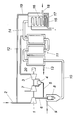
- the illustrated apparatus for the catalytic production of bio-crude oil has a compressor 1 for methane gas, which is obtained from a biogas plant and fed to the compressor 1 via a feed line 2.
- This compressor is driven by a gas turbine 3, with the aid of a partial flow of the compressed methane gas.
- a burner 4 is connected via a branch line 5 to the pressure line 6 of the compressor 1.
- the combustion air for the burner 4 is provided via a compressor 7, which is also driven by the gas turbine 3.
- a jet pump 8 is applied, which is connected on the suction side with a hydrogen line 9, so that the methane gas serves as a propellant gas for the jet pump 8 and sucks hydrogen through the hydrogen line 9.
- the hydrogen obtained from the upstream biogas plant is thus mixed by means of the jet pump 8 with the methane gas and the mixture is fed as synthesis gas via a pressure line 10 to a catalyst 11, which is designed as a multi-stage fixed bed catalyst in a conventional manner.
- a catalyst 11 which is designed as a multi-stage fixed bed catalyst in a conventional manner.
- the exhaust gases of the gas turbine 3, which are supplied to the catalyst 11 via an exhaust pipe 12 serve.
- the cooled exhaust gas is withdrawn via a line 13 and can be delivered to the biogas plant.
- the mixture of hydrogen and methane is converted in the catalyst 11 into a product gas of higher hydrocarbons, which flows via a product gas line 14 into a condenser 15 whose cooling circuit is designated 16.
- the condensed hydrocarbons form a sump 17, from which the organic crude oil can be withdrawn via a discharge line 18.
- Contains the product gas excess methane this methane can be eliminated from the condenser 15 via a return line 19 and the feed line 2 for the methane gas from the biogas plant in the circulation to be conveyed.
- the excess methane in the gas turbine 3 can be worked off and used, for example, for power generation.
- the gas turbine 3 drives a generator 20 for this purpose.
- the pressurization of the synthesis gas in the pressure line 10 only needs to ensure the gas delivery through the catalyst 11, so that in the region of the condenser 15, the gas pressure is largely reduced. This means that the pressure load of the pressure-carrying parts can remain limited, which represents advantageous design conditions for the device.
Landscapes
- Chemical & Material Sciences (AREA)
- Chemical Kinetics & Catalysis (AREA)
- Oil, Petroleum & Natural Gas (AREA)
- Organic Chemistry (AREA)
- Engineering & Computer Science (AREA)
- General Chemical & Material Sciences (AREA)
- Organic Low-Molecular-Weight Compounds And Preparation Thereof (AREA)
- Production Of Liquid Hydrocarbon Mixture For Refining Petroleum (AREA)
Abstract
Description
- Die Erfindung bezieht sich auf ein Verfahren zum katalytischen Herstellen von Bio-Rohöl, wobei ein aus Biomasse gewonnenes, Wasserstoff enthaltendes Synthesegas in einem Katalysator unter Wärmezufuhr zu einem Produktgas aus höheren Kohlenwasserstoffen umgesetzt und dann zum Abscheiden des Rohöls kondensiert wird, sowie auf eine Vorrichtung zum katalytischen Herstellen von Bio-Rohöl.
- Zum Herstellen von Bio-Rohöl aus Biomasse ist es in Anlehnung an das Fischer-Tropsch-Verfahren bekannt, aus der Biomasse durch Pyrolyse ein im Wesentlichen Wasserstoff und Kohlenmonoxid enthaltendes Synthesegas zu gewinnen, das in einem Festbettkatalysator unter Druck und Wärme zu einem Produktgas aus gesättigten und ungesättigten Kohlenwasserstoffen unterschiedlicher Kettenlängen umgesetzt wird, das zu Bio-Rohöl kondensiert wird. Nachteilig bei diesem bekannten Verfahren zum katalytischen Herstellen von Rohöl aus Biomasse ist vor allem, dass eine wirtschaftliche Umsetzung des Verfahrens großtechnische Anlagen erfordert. Außerdem reicht der im Synthesegas enthaltene Wasserstoff nicht für eine weitgehende katalytische Umsetzung des Synthesegases in entsprechende Kohlenwasserstoffe aus, sodass zusätzlich Wasserstoff zugeführt werden muss.
- Der Erfindung liegt somit die Aufgabe zugrunde, ein Verfahren anzugeben, mit dessen Hilfe Biomasse auch in kleineren Anlagen wirtschaftlich in Rohöl umgesetzt werden kann, und zwar ohne zusätzliche Wasserstoffquellen zur Verfügung stellen zu müssen.
- Ausgehend von einem Verfahren zum katalytischen Herstellen von Bio-Rohöl der eingangs geschilderten Art löst die Erfindung die gestellte Aufgabe dadurch, dass durch Methanogenese aus einer durch Hydrolyse und Versäuerung aufgeschlossenen Biomasse gewonnenes Methan mit während der Versäuerung der Biomasse anfallendem Wasserstoff gemischt und als Synthesegas dem Katalysator zugeführt wird.
- Die Erfindung nützt den Umstand aus, dass sich ein Gemisch aus Methan und Wasserstoff vorteilhaft katalytisch zu einem Produktgas aus höheren Kohlenwasserstoffen umsetzen lässt, sodass von einer Biogaserzeugung ausgegangen werden kann, die in herkömmlicher Art einen anaeroben Aufschluss einer beispielsweise im landwirtschaftlichen Bereich anfallenden Biomasse durch eine Hydrolyse und eine Versäuerung mit nachfolgender Methanogenese umfasst. Aus dem gewonnenen Biogas, das vor allem Methan und Kohlendioxid enthält, braucht lediglich das Kohlendioxid abgetrennt zu werden, um das verbleibende Methan mit Wasserstoff zu mischen, der bei der Versäuerung der Biomasse anfällt und die nachfolgende Methanogenese behindert. In diesem Zusammenhang ist zu bedenken, dass einerseits die Versäuerung rascher als die Methanogenese abläuft und anderseits die methanogenen Bakterien empfindlich auf eine Übersäuerung reagieren, sodass es vorteilhaft ist, den bei der Versäuerung anfallenden Wasserstoff beispielsweise durch das Anlegen eines elektrischen Feldes abzuziehen, wodurch nicht nur günstigere Verhältnisse für die Methanogenese geschaffen, sondern auch die Versäuerung mit dem Vorteil beschleunigt werden kann, dass für das Mischen des Synthesegases ausreichend Wasserstoff zur Verfügung gestellt werden kann.
- Ist ein Methanüberschuss vorhanden, so spielt dies hinsichtlich der Verfahrensführung keine Rolle, weil das dann im Produktgas enthaltene Methan während der Kondensierung des Produktgases abgetrennt und wieder zur Bildung des Synthesegases rückgeführt werden kann.
- Zur Durchführung eines solchen Verfahrens zum katalytischen Herstellen von Bio-Rohöl kann von einem beheizbaren, über eine Druckleitung mit Synthesegas beaufschlagbaren Katalysator zum Umsetzen des Synthesegases in ein Produktgas aus höheren Kohlenwasserstoffen und mit einem an den Katalysator angeschlossenen Kondensator für das Produktgas ausgegangen werden. Um ein entsprechendes Synthesegas aus einer Mischung von aus einer Biogasanlage gewonnenem Methan und Wasserstoff zu erhalten, kann die Druckleitung für das Synthesegas über eine Strahlpumpe einerseits an eine Druckleitung eines mit Methangas beaufschlagbaren Verdichters und anderseits an eine Wasserstoffleitung angeschlossen werden. Das mittels des Verdichters hochgespannte Methangas dient als Treibgas für die Strahlpumpe, sodass über die Strahlpumpe dem Methangas das Wasserstoffgas in einem vorgegebenen Verhältnis zugemischt wird und mit dieser Mischung der Katalysator unter einem entsprechenden Druck beaufschlagt werden kann.
- Damit für den Antrieb des Verdichters keine Fremdenergie eingesetzt zu werden braucht, kann der Verdichter durch eine mit einem Teilstrom des Methans als Brenngas betreibbare Gasturbine angetrieben werden. Die Verwendung einer mit einem Teil des aus einer Biogasanlage gewonnenen Methans als Brenngas befeuerbaren Gasturbine bringt außerdem den Vorteil mit sich, dass der Katalysator mit Hilfe der Abgase dieser Gasturbine beheizt werden kann, womit eine vorteilhafte Energieausnützung sichergestellt wird, zumal gegebenenfalls anfallende Überschussenergie in der Gasturbine zur Stromerzeugung abgearbeitet werden kann. In diesem Zusammenhang stellt auch die Rückleitung eines aus dem Produktgas abgeschiedenen Methanüberschusses eine vorteilhafte Möglichkeit dar, den Gesamtwirkungsgrad einer solchen Anlage hoch zu halten.
- Anhand der Zeichnung wird das erfindungsgemäße Verfahren zum katalytischen Herstellen von Bio-Rohöl näher beschrieben, und zwar wird eine erfindungsgemäße Vorrichtung zum katalytischen Herstellen von Rohöl in einem schematischen Blockschaltbild gezeigt.
- Die dargestellte Vorrichtung zum katalytischen Herstellen von Bio-Rohöl weist einen Verdichter 1 für Methangas auf, das aus einer Biogasanlage gewonnen und über eine Speiseleitung 2 dem Verdichter 1 zugeführt wird. Dieser Verdichter wird von einer Gasturbine 3 angetrieben, und zwar mit Hilfe eines Teilstroms des verdichteten Methangases. Zu diesem Zweck ist ein Brenner 4 über eine Zweigleitung 5 an die Druckleitung 6 des Verdichters 1 angeschlossen. Die Verbrennungsluft für den Brenner 4 wird über einen Verdichter 7 zur Verfügung gestellt, der ebenfalls von der Gasturbine 3 angetrieben wird. Mit Hilfe des im Verdichter 1 hochgespannten Methangases wird eine Strahlpumpe 8 beaufschlagt, die saugseitig mit einer Wasserstoffleitung 9 verbunden ist, sodass das Methangas als Treibgas für die Strahlpumpe 8 dient und Wasserstoff über die Wasserstoffleitung 9 ansaugt. Der aus der vorgeschalteten Biogasanlage erhaltene Wasserstoff wird somit mittels der Strahlpumpe 8 mit dem Methangas vermischt und die Mischung als Synthesegas über eine Druckleitung 10 einem Katalysator 11 zugeführt, der als mehrstufiger Festbettkatalysator in an sich bekannter Weise ausgeführt ist. Zur Beheizung des Katalysators 11 dienen die Abgase der Gasturbine 3, die dem Katalysator 11 über eine Abgasleitung 12 zugeführt werden. Das abgekühlte Abgas wird über eine Leitung 13 abgezogen und kann an die Biogasanlage abgegeben werden.
- Das Gemisch aus Wasserstoff und Methan wird im Katalysator 11 in ein Produktgas aus höheren Kohlenwasserstoffen umgesetzt, das über eine Produktgasleitung 14 in einen Kondensator 15 strömt, dessen Kühlkreis mit 16 bezeichnet ist. Die kondensierten Kohlenwasserstoffe bilden ja einen Sumpf 17, aus dem das Bio-Rohöl über eine Austragsleitung 18 abgezogen werden kann. Enthält das Produktgas überschüssiges Methan, so kann dieses Methan aus dem Kondensator 15 über eine Rückleitung 19 ausgeschieden und der Speiseleitung 2 für das Methangas aus der Biogasanlage im Kreislauf zugefördert werden. Bei einem im Vergleich zum Wasserstoffangebot bestehenden Überschuss an Methan kann das überschüssige Methan in der Gasturbine 3 abgearbeitet und beispielsweise für eine Stromerzeugung eingesetzt werden. Die Gasturbine 3 treibt zu diesem Zweck einen Generator 20 an.
- Die Druckbeaufschlagung des Synthesegases in der Druckleitung 10 braucht lediglich die Gasförderung durch den Katalysator 11 sicherzustellen, sodass im Bereich des Kondensators 15 der Gasdruck weitgehend abgebaut ist. Dies bedeutet, dass die Druckbelastung der druckführenden Teile beschränkt bleiben kann, was vorteilhafte Konstruktionsvoraussetzungen für die Vorrichtung darstellt.
Claims (6)
- Verfahren zum katalytischen Herstellen von Bio-Rohöl, wobei ein aus Biomasse gewonnenes, Wasserstoff enthaltendes Synthesegas in einem Katalysator unter Wärmezufuhr zu einem Produktgas aus höheren Kohlenwasserstoffen umgesetzt und dann zum Abscheiden des Rohöls kondensiert wird, dadurch gekennzeichnet, dass durch Methanogenese aus einer durch Hydrolyse und Versäuerung aufgeschlossenen Biomasse gewonnenes Methan mit während der Versäuerung der Biomasse anfallendem Wasserstoff gemischt und als Synthesegas dem Katalysator zugeführt wird.
- Verfahren nach Anspruch 1, dadurch gekennzeichnet, dass das im Produktgas enthaltene Methan während der Kondensierung des Produktgases von diesem abgetrennt und zur Bildung des Synthesegases eingesetzt wird.
- Vorrichtung zum katalytischen Herstellen von Bio-Rohöl mit einem beheizbaren, über eine Druckleitung mit Synthesegas beaufschlagbaren Katalysator zum Umsetzen des Synthesegases in ein Produktgas aus höheren Kohlenwasserstoffen und mit einem an den Katalysator angeschlossenen Kondensator für das Produktgas, dadurch gekennzeichnet, dass die Druckleitung (10) für das Synthesegas über eine Strahlpumpe (8) einerseits an eine Druckleitung (6) eines mit Methangas beaufschlagbaren Verdichters (1) und anderseits an eine Wasserstoffleitung (9) angeschlossen ist.
- Vorrichtung nach Anspruch 3, dadurch gekennzeichnet, dass der Verdichter (1) durch eine mit einem Teilstrom des Methans als Brenngas betreibbare Gasturbine (3) antreibbar ist.
- Vorrichtung nach Anspruch 4, dadurch gekennzeichnet, dass der Katalysator (11) mit Hilfe der Abgase der Gasturbine (3) für den Antrieb des Verdichters (1) beheizbar ist.
- Vorrichtung nach einem der Ansprüche 3 bis 5, dadurch gekennzeichnet, dass der Verdichter (1) saugseitig an eine mit dem Kondensator (15) verbundene Rückleitung (19) für aus dem Produktgas abgeschiedenes Methan angeschlossen ist.
Applications Claiming Priority (1)
| Application Number | Priority Date | Filing Date | Title |
|---|---|---|---|
| AT0066609A AT507783B1 (de) | 2009-04-30 | 2009-04-30 | Verfahren zum katalytischen herstellen von bio-rohöl |
Publications (2)
| Publication Number | Publication Date |
|---|---|
| EP2248873A2 true EP2248873A2 (de) | 2010-11-10 |
| EP2248873A3 EP2248873A3 (de) | 2012-06-20 |
Family
ID=42537239
Family Applications (1)
| Application Number | Title | Priority Date | Filing Date |
|---|---|---|---|
| EP10450064A Withdrawn EP2248873A3 (de) | 2009-04-30 | 2010-04-22 | Verfahren und Vorrichtung zum katalytischen Herstellen von Bio-Rohöl |
Country Status (2)
| Country | Link |
|---|---|
| EP (1) | EP2248873A3 (de) |
| AT (1) | AT507783B1 (de) |
Families Citing this family (1)
| Publication number | Priority date | Publication date | Assignee | Title |
|---|---|---|---|---|
| CN112557441B (zh) * | 2020-11-30 | 2022-04-15 | 西南石油大学 | 输气管道喷射火对邻近液烃管安全性影响实验平台及方法 |
Family Cites Families (1)
| Publication number | Priority date | Publication date | Assignee | Title |
|---|---|---|---|---|
| US5938975A (en) * | 1996-12-23 | 1999-08-17 | Ennis; Bernard | Method and apparatus for total energy fuel conversion systems |
-
2009
- 2009-04-30 AT AT0066609A patent/AT507783B1/de not_active IP Right Cessation
-
2010
- 2010-04-22 EP EP10450064A patent/EP2248873A3/de not_active Withdrawn
Non-Patent Citations (1)
| Title |
|---|
| None |
Also Published As
| Publication number | Publication date |
|---|---|
| AT507783B1 (de) | 2010-08-15 |
| EP2248873A3 (de) | 2012-06-20 |
| AT507783A4 (de) | 2010-08-15 |
Similar Documents
| Publication | Publication Date | Title |
|---|---|---|
| EP1931753B1 (de) | Verfahren zur erzeugung von methan und/oder methanhydrat aus biomasse | |
| EP2464617B1 (de) | Verfahren und anlage zum bereitstellen eines kohlenwasserstoff-basierten energieträgers unter einsatz eines anteils von regenerativ erzeugtem methanol und eines anteils von methanol, der mittels direktoxidation oder über partielle oxidation oder über reformierung erzeugt wird | |
| EP3052435B1 (de) | Verfahren zur speicherung von elektrischer energie | |
| EP3390693B1 (de) | Verfahren zur erzeugung von kohlenstoff-basierten sekundärenergieträgern oder basischemikalien | |
| EP2406190B1 (de) | Verfahren und anlage zur verwertung von biomasse sowie blockheizkraftwerk | |
| EP2049232A1 (de) | Verfahren zur wiederaufarbeitung von verbrennungsprodukten fossiler brennstoffe | |
| DE1717156A1 (de) | Verfahren und Apparatur zur Dampfreformierung von Kohlenwasserstoffen | |
| WO2018130535A1 (de) | Verfahren und vorrichtung zur herstellung von organischen verbindungen aus biogas | |
| WO2015120983A1 (de) | Verfahren und anlage zum erzeugen von biomethan | |
| DE102012105736A1 (de) | Verfahren zur Speicherung von Elektroenergie | |
| EP2650257B1 (de) | Vorrichtung zur synthese von regenerativem methanol aus co2-haltigem methangas | |
| CN220579415U (zh) | 一种电解水制氢耦合合成氨系统 | |
| AT507783B1 (de) | Verfahren zum katalytischen herstellen von bio-rohöl | |
| DE102012013000A1 (de) | Prozess zur kombinierten Herstellung von Wasserstoff und Ethylen | |
| CN206872610U (zh) | 生物质热电联产的生态养猪系统 | |
| US12435277B2 (en) | Cost efficient integration of hydrothermal liquefaction and wet oxidation wastewater treatment | |
| CN120290289A (zh) | 一种一体化厌氧发酵自供热生产生物天然气系统及方法 | |
| EP2505632A2 (de) | Verfahren und Anlage zum Erzeugen von Brenngas und elektrischer Energie | |
| DE102008056318A1 (de) | Verfahren zur weitgehend autarken Versorgung eines abgeschlossenen Siedlungsgebiets mit den Endenergien elektrische Energie, Heizgas und Kraftstoff auf der Basis Biomasse | |
| DE102022125444B4 (de) | Verfahren zur Entfernung eines Methananteils aus Offgas und Biogasanlage | |
| EP3022277B1 (de) | Verfahren zur nutzung von biomasse zur erzeugung von elektrischer energie und wärmebereitstellung durch pyrolyse; vergasung und verbrennung und zur umwandlung von wärmeenergie in elektrische energie | |
| DE2447913A1 (de) | Verfahren zur nutzung von waerme | |
| CN221156580U (zh) | 一种co变换耦合甲醇合成工艺装置 | |
| BE1029758B1 (de) | Ammoniak-Synthese-Vorrichtung | |
| WO2013153163A1 (de) | Verfahren und vorrichtung zur herstellung von flüssigem roheisen und/oder von eisenschwamm |
Legal Events
| Date | Code | Title | Description |
|---|---|---|---|
| PUAI | Public reference made under article 153(3) epc to a published international application that has entered the european phase |
Free format text: ORIGINAL CODE: 0009012 |
|
| AK | Designated contracting states |
Kind code of ref document: A2 Designated state(s): AT BE BG CH CY CZ DE DK EE ES FI FR GB GR HR HU IE IS IT LI LT LU LV MC MK MT NL NO PL PT RO SE SI SK SM TR |
|
| AX | Request for extension of the european patent |
Extension state: AL BA ME RS |
|
| PUAL | Search report despatched |
Free format text: ORIGINAL CODE: 0009013 |
|
| RIC1 | Information provided on ipc code assigned before grant |
Ipc: C10G 50/00 20060101AFI20120509BHEP Ipc: C07C 2/00 20060101ALI20120509BHEP Ipc: B01J 8/04 20060101ALI20120509BHEP |
|
| AK | Designated contracting states |
Kind code of ref document: A3 Designated state(s): AT BE BG CH CY CZ DE DK EE ES FI FR GB GR HR HU IE IS IT LI LT LU LV MC MK MT NL NO PL PT RO SE SI SK SM TR |
|
| AX | Request for extension of the european patent |
Extension state: AL BA ME RS |
|
| STAA | Information on the status of an ep patent application or granted ep patent |
Free format text: STATUS: THE APPLICATION IS DEEMED TO BE WITHDRAWN |
|
| 18D | Application deemed to be withdrawn |
Effective date: 20121221 |